(2015 Apr 11, &ff)
[Note, 2016 Jan 14: I hope to resume work on this project fairly soon. In the meanwhile, I need to add a link to the work of Sothory Yun, who has made a detector of similar design. That will happen when I have a few more moments to spare.]
In email correspondence a few weeks ago, Jeff Hecht bemoaned the fact that although it is now easy to buy a decent cheap multimeter, there are no decent cheap laser power meters. I thought about that, and it occurred to me that I own two surplus power meter heads that are based on an extremely straightforward design strategy. It should be really easy and relatively inexpensive to build a variant of this design.
The heads I have are intended for use with lasers that put out several watts, and the signal they produce is less than 1 millivolt per milliwatt of input. The DIY version will behave similarly, so I will probably include a small instrumentation amplifier for use with low-power lasers.
If you apply a voltage across a thermoelectric device, one side gets hot and the other side gets cold. This works just fine in reverse: if you apply energy to one side and remove it from the other side (so that there’s a temperature difference across the device), it generates a voltage. We are going to hope that the voltage is reasonably linear with the difference in temperature across the device. (I would certainly expect it to be linear in a broad general sense, but if the curve has a “toe” we may be on it at low power inputs.)
Most laser beams are quite narrow, and it is important to spread out the heat in order to get a good response from the TEC; I decided to use a copper heat-spreader (intended for use in a computer) that is 1 mm thick. Copper reflects extremely well in the IR, so it is important to cover the surface with flat black paint or some other coating that absorbs the vast majority of light, across a broad range of wavelengths. (I can easily “see” my hand with either of the sensor heads I own.)
NOTE: This type of sensor is inherently slow because of the [relatively] large thermal mass involved. If you need a high-speed detector, you will have to use something very different.
As a start, I acquired a TEC on eBay. I looked for a 10-watt one, because I don’t need anything larger for this, but although I have bought that size in the past I didn’t find any this time; I settled for something considerably larger. The one I bought is a 40-mm square, and the copper plates I found (also on eBay) are 42-mm squares. The heat generated in the spreader by the incoming beam has to be transmitted to the front plate of the TEC; I went looking for thermal conductive compound, and found that it is possible to get diamond-loaded paste. It is stiff, and must be warmed up before it will come out of the tube, but I don’t mind. Diamond is a better heat conductor than silver, and the diamond-loaded material is a lot cheaper than the silver-loaded equivalent.
As I mention above, it is necessary to stabilize the temperature of the back side of the TEC. I acquired a nice heavy old brass hinge to use as a heatsink, and then Chris Olsen was kind enough to give me a round brass flange that has mounting holes; either of these should do nicely for modest power levels. (I am using the flange for the first version; if I use the hinge for another sensor, I will clamp or glue the two sides together with thermal conductive paste between them, in order to get best use of all of the mass.)
It is crucially important to be able to calibrate the sensor. If you have a laser with known output power you can just measure it and divide to get the number of millivolts per milliwatt of input, but that is not a likely scenario. In the absence of a calibrated laser, a good way to do this is to include a known source of heat in the design. I got some 40-gauge nichrome wire, which is well characterized (67.6 ohms/foot, according to the label), to use as a calibration resistance. Once around the edge of the TEC (or the heat spreader) is a distance of about 160 (or 168) mm, which should provide a resistance of just under 35½ ohms. To calibrate the sensor you apply a known voltage to the resistance wire, which dissipates the power and produces a known amount of heat, and you measure the output of the TEC. It is, obviously, important to have an accurate measurement of the resistance, as that governs the accuracy of the calibration. [NOTE: It is a good idea to check the calibration from time to time, in case the characteristics of the TEC change.]
Clearly, the calibration wire has to be insulated from the heat-spreader plate; as of April 11th I am thinking about how to accomplish this without interfering too badly with the transfer of heat into the spreader.
(On April 16th, I decided to see whether nail polish would work. It does; I was able to put a rather thin coat on a piece of the wire by hanging it and pulling the brush from the bottle down it.)
It is not very easy to attach the resistance wire to the heat spreader; be patient and careful! I originally thought I would put it on the back face, around the edge of the TEC, but it proved somewhat easier to put it around the edge of the copper plate. I also tried attaching it to the extension wire that goes to the calibration connector, and then gluing it in place on the copper. That failed, and I ended up attaching it to the copper first. It was much easier to hook it up to the extension wire after gluing it around the heat spreader than before.
NOTE: It appears to be essentially impossible to solder nichrome wire. You should probably use some type of electrically conductive glue (silver-loaded epoxy, for example) to attach it. Because I don’t have any conductive glue handy at the moment, I ended up winding the nichrome several times around the copper wire that goes to the connector, and melting solder around it. That’s not a good method, and it may not be stable. For a future version, I think I may try to electroplate copper on the ends of the nichrome so I can solder directly to it, and we’ll see how well that works.
One other key issue: it is necessary to restrict the field of view of the sensor. (As I mention, it can easily detect the long IR that a person or other warm object emits.) I will probably use something extremely simple, possibly just a cardboard tube from a roll of toilet paper, painted flat black on the inside (and possibly with a piece of white paper glued to the outside). If I end up with a tube that has smaller diameter than the size of the heat spreader, which seems likely, I will probably put a piece of aluminum foil in front of the part of the active area that is outside the tube, to prevent stray light from reaching it.
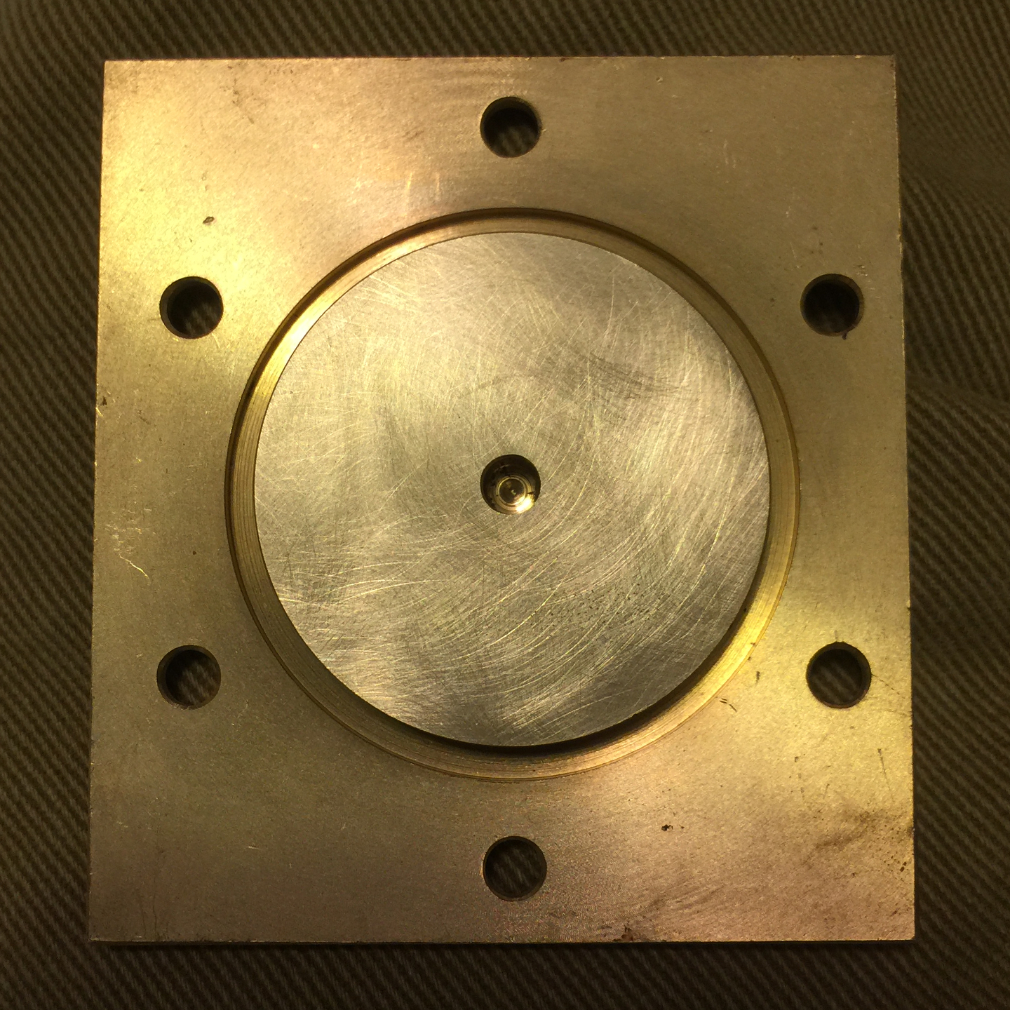
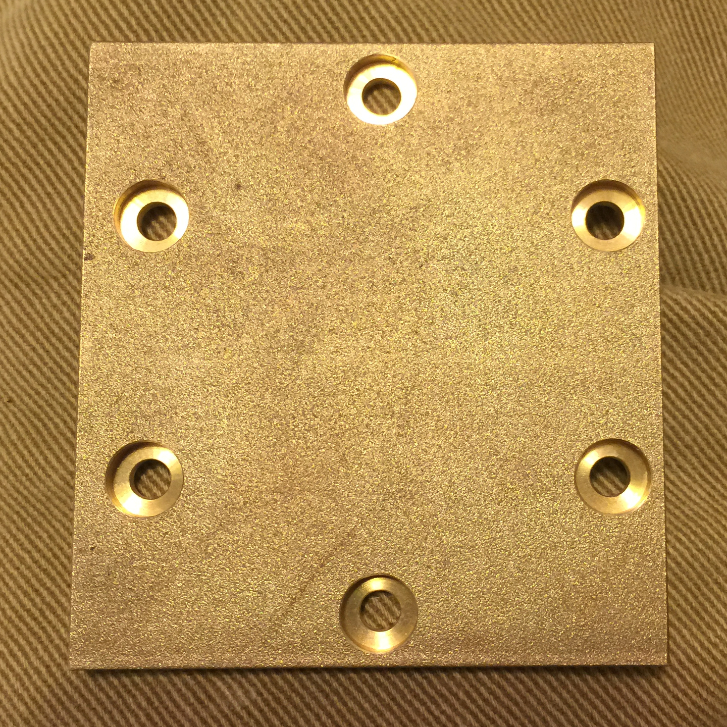
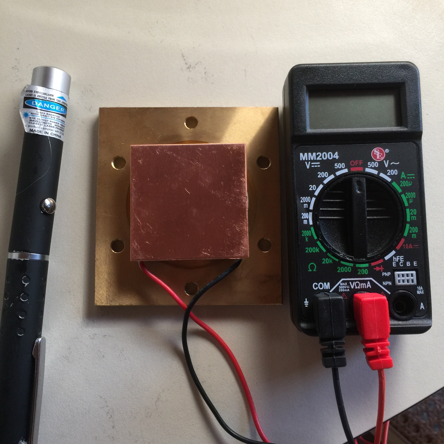
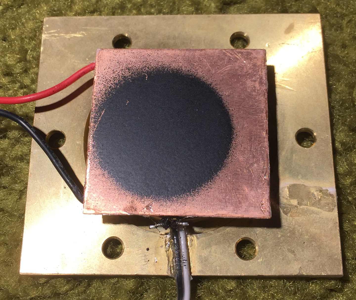
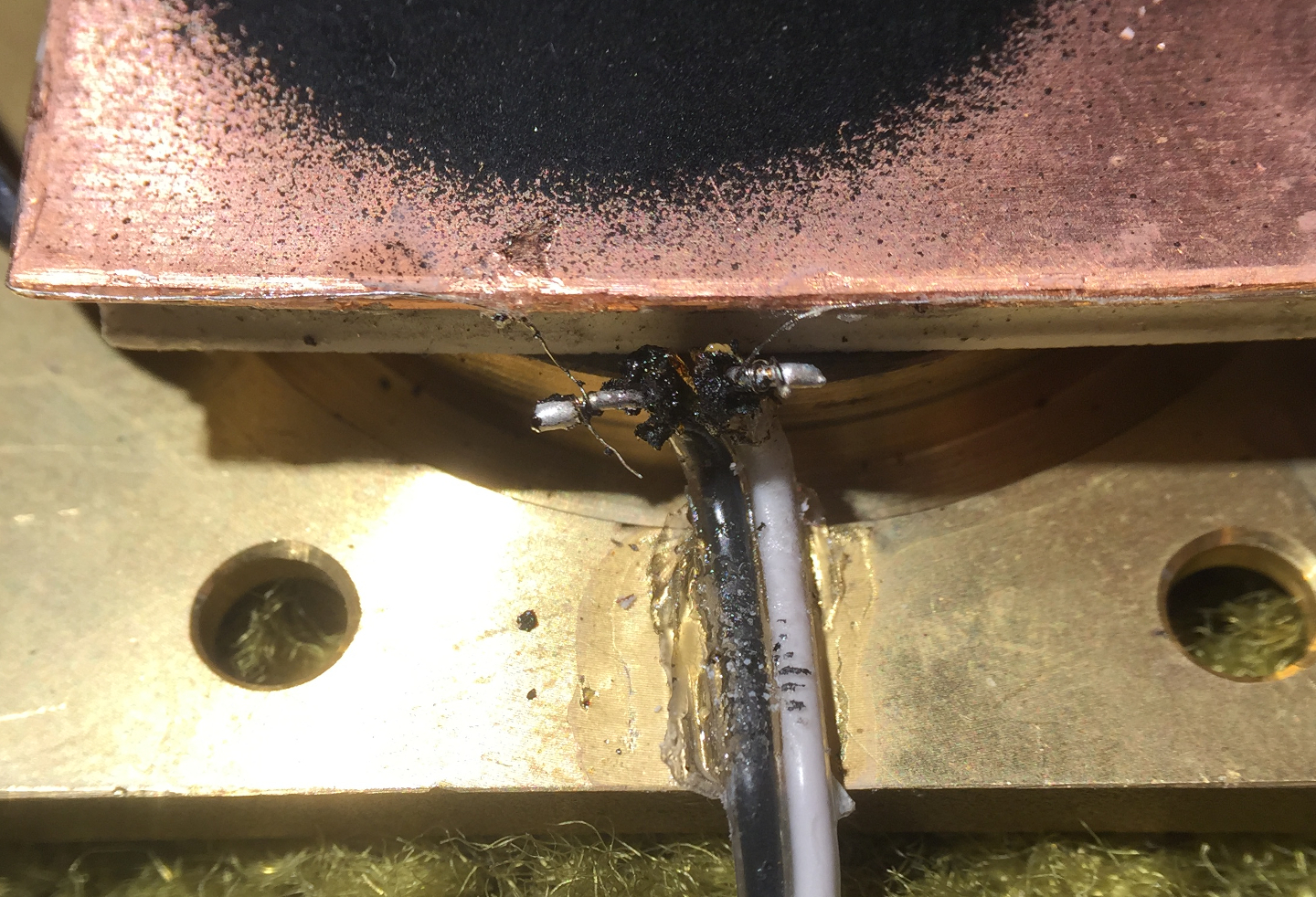
The first photo shows the front of the brass plate, after I sandpapered the active region to remove the texture. (I neglected to take a photo before I did that, so the second photo shows the [same] texture on the back.) The third photo shows the sensor preassembled, with the parts held in place only by thermal paste, and without the calibration resistance; that was enough to allow a preliminary test: I shined a violet laser pointer at the copper, and got a few millivolts from the TEC. (Copper reflects extremely well in the IR, but not in the UV or the shorter wavelength parts of the visible.) The fourth shows the assembled sensor, but without a barrel on the front and without anything to block stray light. The paint is scratched, and I am thinking about removing it and repainting. The fifth photo is a macro that shows the way I attached the calibration resistance to the extension wire. I have not yet tested to see whether this configuration will work well enough.
If this all looks rather crude, that’s because it is. I am primarily concerned with whether it is possible to build a decent power sensor cheaply and easily, and only secondarily with what it looks like.
The resistance is more than 40 ohms, somewhat higher than
I had expected. It is entirely possible that this is
related to the fact that the solder did not wet the surface
of the nichrome. As I say, I may try plating copper onto
the nichrome to see whether that results in a better join.
That should also have the advantage of leaving less of the
current-carrying part of the nichrome hanging in the air,
where it decreases the accuracy of the calibration.
More as it transpires...
To the Main index for my research
Contact:
Email: use my first name (only 3 letters; no “H”), at the domain that’s in the URL for this page.
Last modified: Thu Jan 14 12:59:43 EST 2016