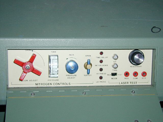
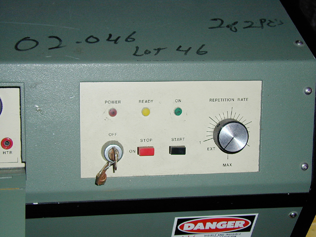
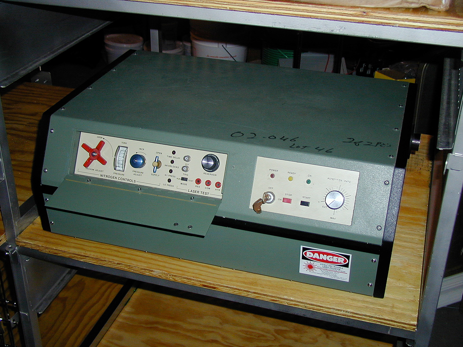
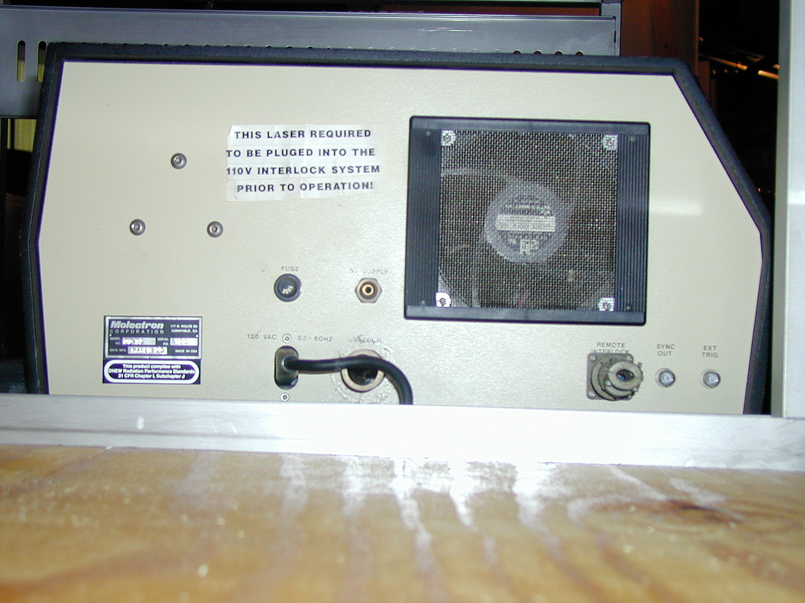
In the Spring of 2002, we bought a used Molectron N2 laser on eBay. Here are a few photos of the case & controls; if you want more detail you can click any of the small images for a 640x480 px version, or use the text links below the small images.
It proved trivial to bring this machine online, when I finally got to it, in the Spring of 2005 (argh): I removed a broken cable-tie from inside the case, powered it up, and adjusted the thyratron reservoir voltage and the mirror alignment.
Here are two fairly representative traces, taken on 3 June, 2005 using a Tektronix 7104 scope, a 7A26 (if I remember correctly) plugin, and a nice fast photodiode sent to me by Howard Davidson a while back:
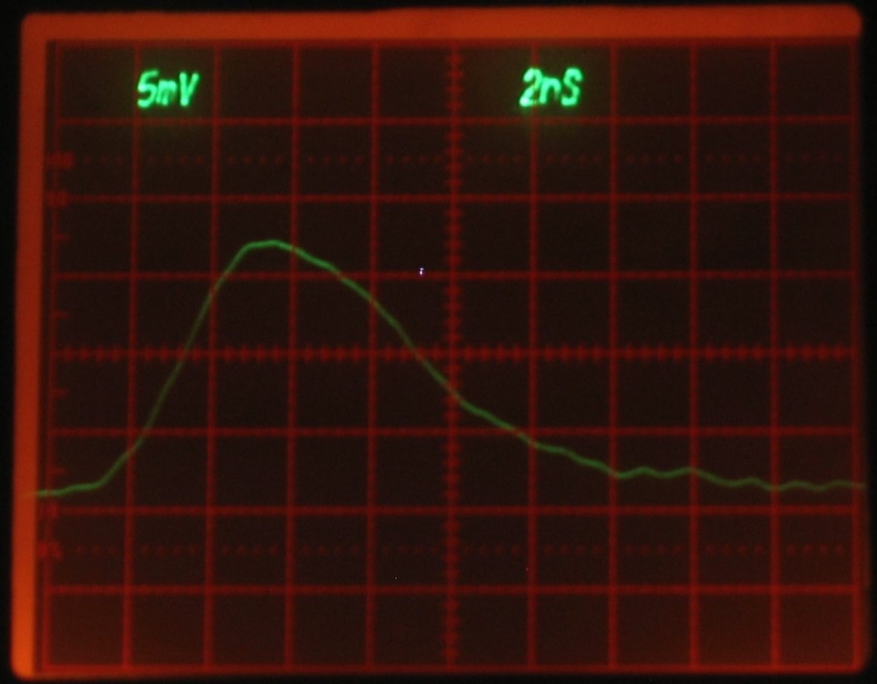
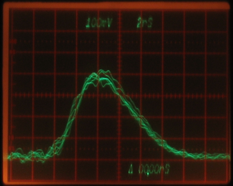
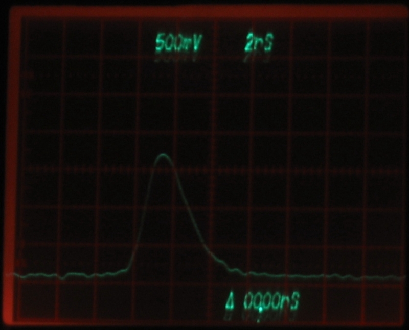
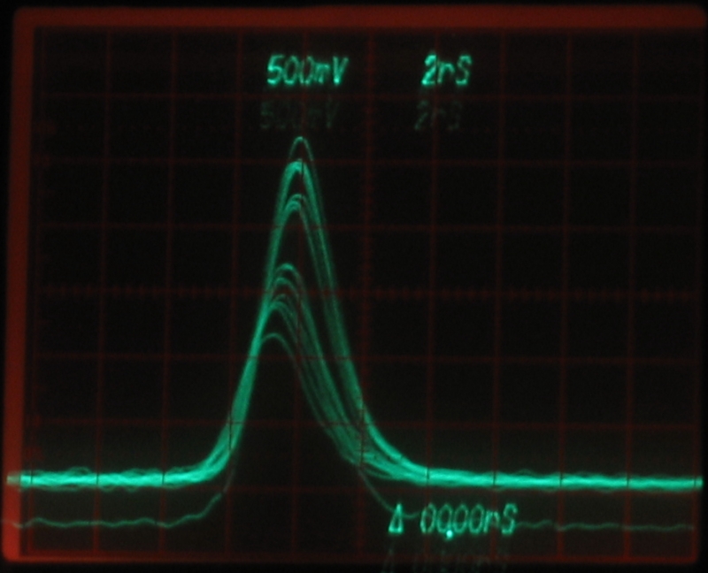
[Note, added on 2006 January 22 and 24: I have taken more photos of ’scope traces, this time using a 7A29 plugin, which is faster than the 7A26 or the 7A19. There is more electrical noise, or perhaps the faster plugin is simply doing better at showing us the noise that has been there all along. Here, anyway, is a representative single trace, and an exposure showing perhaps a dozen; these demonstrate a little problem, which I’ll say more about in a moment.
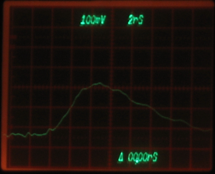

My apologies for the fuzziness. I’m not sure I had the focus quite right, and the camera shook a bit when I pressed the shutter button. When I get a chance, I may try to improve upon these.
Note the pulsewidth, btw, which appears to be
approximately 8 nsec FWHM. I am not really sure about
this; the rather long fall time worries me. Note, also,
the fact that the trace at the right edge is almost half
a box higher than it is at the left edge. I am beginning
to think that there is an impedance matching issue here.
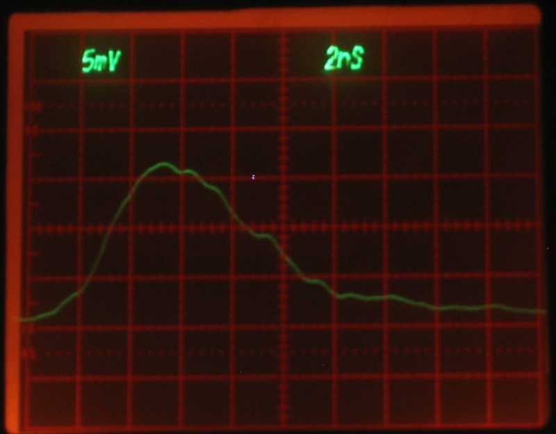
(24 January, 2006)
I found a piece of RG-58A/U cable about 8 inches long,
and replaced the previous cable with it. RG-58A/U is a
50-ohm cable, and should match both the detector head
and the scope input impedances fairly well. Here are the
results of the change:
As you can see, the long tail has disappeared, and the
trace at the right edge of the screen is at the same
height as it is on the left edge. The FWHM pulsewidth
is now revealed to be no more than about 6.5 nsec. [Let
that be a proper caution to you.]
In any case, once I had the machine up and flying I
decided to run the usual dyes with it, in the process
of which I learned a few things....
(mid-May, 2005. NOTE: You can click any of the
small images to get an 800-x-600-px enlargement, except
for the photo of Milan Karakas’s dye cell, which
is 1024 x 768. For any of my photos, you can get a
2272-x-1704-px image by changing ".8c." in the filename
of the 8x6 large image to ".22c."; Milan’s 1024 x 768
is the largest size currently available.)
Here is a photo of the dye laser setup, with the grating
moved off to the left a bit, and the nitrogen beam focused
to a line on the front of the dye cuvette. (Ordinarily, I
position the grating considerably closer to the cuvette.)
Yes, the cuvette holder is rude, crude, boorish, and
socially unacceptable. It’s a lot better than it was,
though, and I’m still working on it.
The mirror and grating are tilted to align them with the
region of dye that is being pumped by the N2 laser, rather
than with the walls of the cuvette. If I remove either or
both of them the dye will continue to lase, using the
reflections from the cuvette walls as its feedback source.
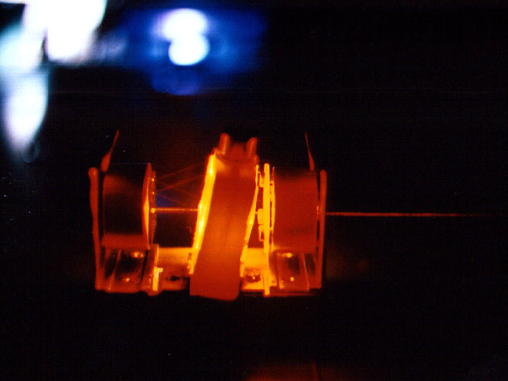
Here’s a photo of a dye cell that Milan Karakas built, being
pumped by one of his nitrogen lasers (the blue glow in the
background is the nitrogen laser; we’re looking at the back
of the dye cell). You’ll notice that the windows are several
degrees away from perpendicular to the dye laser beam, and
that some reflections are visible. I believe that the dye
here is R6G.
When I have time, I will provide a set of photos illustrating
mirror adjustment, which is most easily performed with the
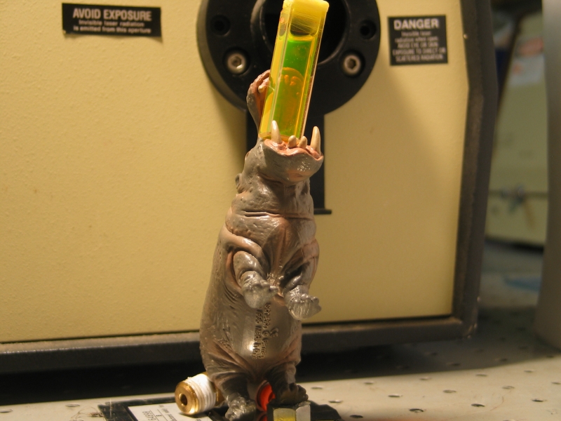
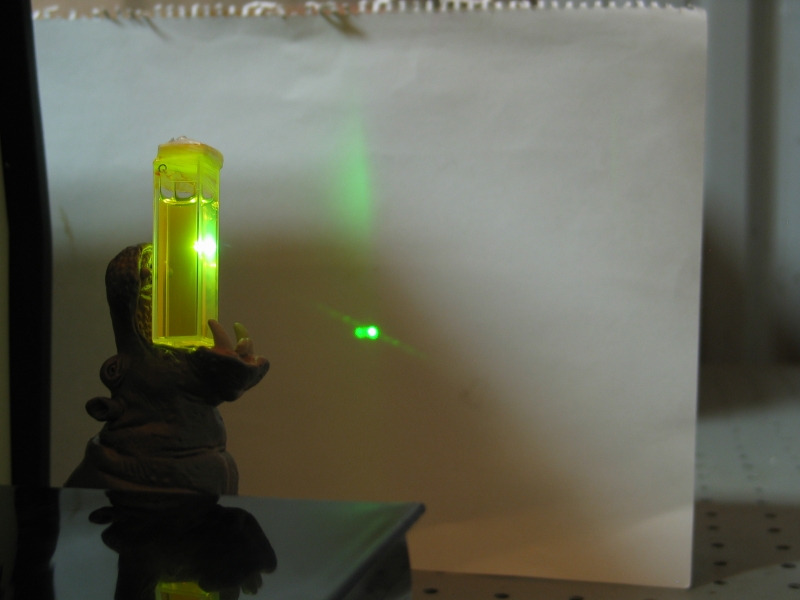
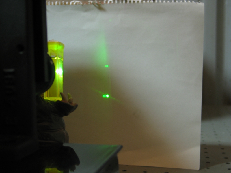
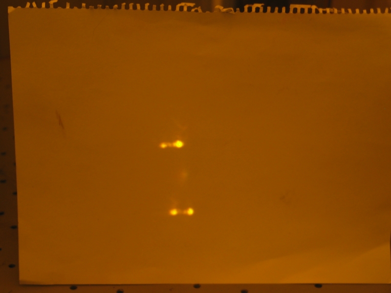
grating removed. In the meanwhile, here’s a slightly different
setup (upper), showing the cuvette lasing with no external
feedback (left lower) and with a mirror (right lower):
(“Mr. Hip” cuvette holder notion provided
by the fiendish and unregenerate
Miss LisaJulie. Mr. Hip’s footstool and couch
by Meubles Bazilians de Paris, depuis 1614. Next up,
micrometer adjustment of Mr. Hip’s butt for precise
control of the cuvette tilt angle...)
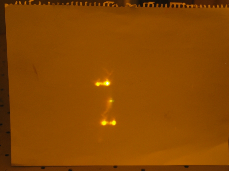
I think the defocused vertical band of green in the lower
two photos may be superluminescent lasing, in which the
medium operates with such high gain that it has substantial
single-pass output — it lases without any feedback. (A
nitrogen laser without any end mirror and with misaligned
end windows operates in this mode. The reason why the
nitrogen laser produces a beam instead of a cloud like the
one you see here is that the channel of the nitrogen laser
is many times longer than it is wide.) I stacked the deck
for these photos by adjusting the position of the focusing
mirror (not visible in any of these photos) so that the
excited region of dye was only a few millimeters long and at
most a millimeter across and was, at least vaguely, in the
shape of a very short horizontal stripe. Because of that,
the superluminescent lasing [assuming I’ve identified
it correctly; see
Dr. Rüdiger Paschotta’s excellent encyclopedia]
was brightest across from the cuvette and at about the
same height off the bench, or perhaps a bit higher
— the excited region was only approximately
horizontal, and its shape was not a very straight
line. Also, as I say, it was quite short.
The bright lower dot is the dye using the cuvette walls for
feedback, and the not-so-bright dot above it in the third
photo is essentially how I tell when I have the mirror
correctly aligned, before I put the grating into place. The
reason why the spot isn’t particularly bright is that
the light has only passed through the dye twice. As you can
see, however, even just a second pass is enough to produce a
more-or-less-directed beam, though that’s partly
because the mirror is a few millimeters away from the
excited region. (In the abstract, putting a [perfect] mirror
in the center of a fully symmetric excited region wouldn’t
change the output at all.) The further away the mirror is,
the more it narrows the beam; but of course with N2 pumping
you don’t have much time, so you want to put the mirror as
close to the dye as you can, within reason.
Adjusting things to achieve the desired condition (mirror
aligned with cuvette and excited region; grating or second
mirror aligned with cuvette, excited region, and first
mirror) can be tricky, and I hope to put a more detailed set
of photos in place when I have time.
Note, btw, that none of these kinds of lasing actually
prevents any of the others from occurring: in the third
photo, the dye is lasing all three ways at the same
time. This has implications for tuning — you want
to provide as much feedback as you can, in the hope that
tuned lasing will use as much of the available
excitation as possible. This also helps explain why any
attempt to tune a pulsed dye laser by injecting a HeNe
beam or a laser pointer beam into it is guaranteed to
fail: the dye is putting out thousands of watts
of “junk” light, and it will casually ignore
your feeble attempt to distract it from amplifying its
own spontaneous emission. It also explains why you want
to put the mirror and grating as close to the cuvette as
you can, if its walls are parallel to each other: the
round-trip time for light inside the cuvette is less
than 100 psec. The more bounces it can make the higher
the gain will be, and the less energy will be available
for tuned output. This is an argument for making your
own cuvette, so that you can deliberately misalign its
walls slightly. (I have built cuvettes of that sort, and
when time permits I will try to add a set of photos to
demonstrate the differences.)
The cuvette, btw, contains Fluorescein and a small amount
of 7-Diethylamino-4-Methyl-Coumarin, in 91% isopropanol
to which I have added a drop or two of very strong ammonia.
Fluorescein on its own doesn’t absorb particularly well at
337 nm, so even though it has very good quantum efficiency,
it’s difficult to lase with nitrogen laser pumping. I use
the Coumarin, which absorbs the pump light extremely well
and emits at a wavelength that is more readily absorbed
by the Fluorescein, to help it along. This technique,
while of limited utility, clearly works with some dye pairs.
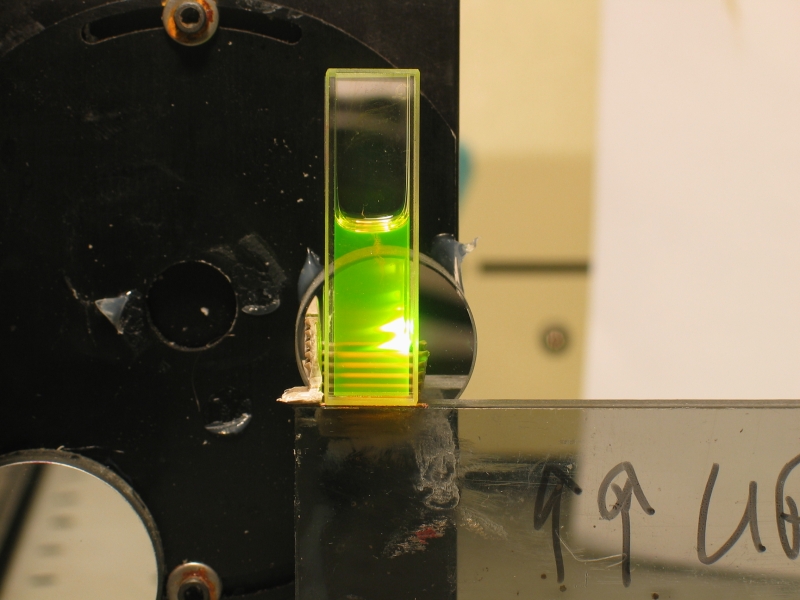
Here are some photos to illustrate that. First, Fluorescein
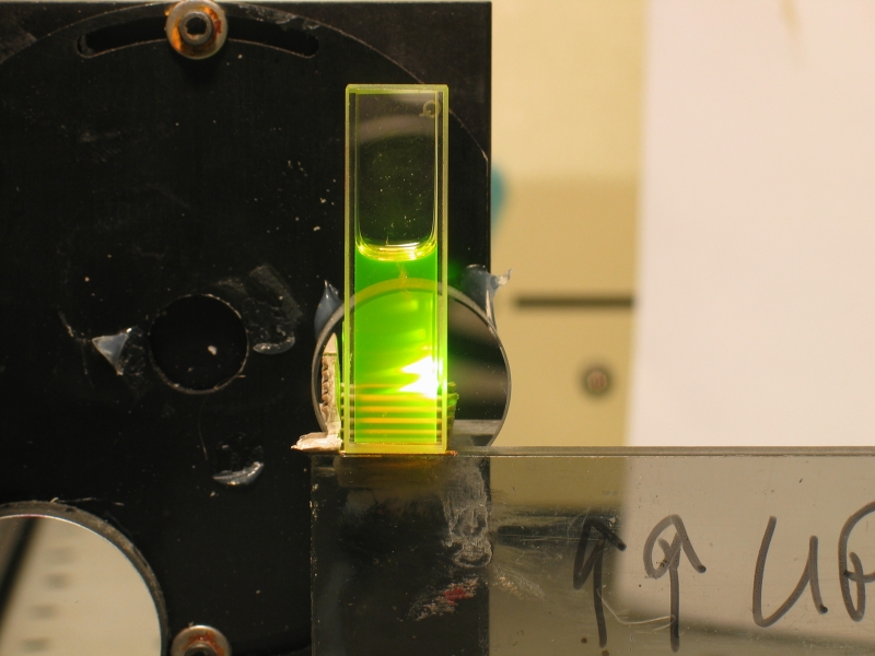
in 91% isopropanol. The solution doesn’t lase. Second, I add
a drop of concentrated aqueous ammonia, and the fluorescence
gets a bit brighter, but the absorption depth is still too
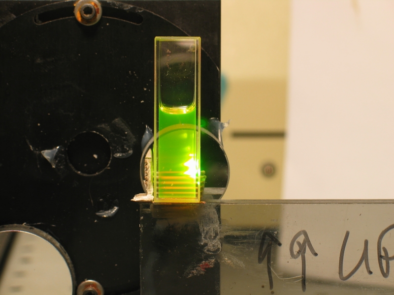
large. Third, I add more Fluorescein. The absorption depth
decreases, but it is still too big, so the solution doesn’t
lase, or perhaps just barely begins to reach threshold.
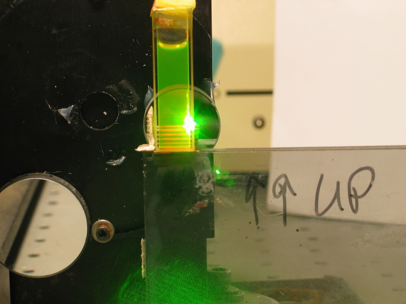
Fourth, I add a small amount of
7-Diethylamino-4-Methyl-Coumarin, possibly not even
enough to lase by itself, and the resulting solution
definitely lases — note the laser speckle at the
bottom of the image. (This last photo is actually a
different batch of solution, which shows the effect more
clearly than the original batch did.)
Notice that the middle of the spot is white and
thoroughly overexposed in several of these, particularly
the last one. Even though I was looking at the cuvette
from an angle, the sensor in my camera was damaged by
the beam. “Do Not Stare [Or Even Look] Into Laser
With Remaining Camera.”
(24 January, 2006)
Here is a pair of oscilloscope photos, showing the pulse
from fluorescein, but without any external mirrors. This
is a mixture of superluminescent lasing and reflection
from the cuvette walls.
This is a very old dye solution, and probably
isn’t fully representative. Even so, it shows
risetime of about a nanosecond and three quarters, and
pulsewidth of perhaps 3 nsec FWHM, which is close to
what you would expect if the dye is lasing only when the
nitrogen laser is near the peak of its output. (Remember
that as long as the dye is lasing we are not going to
see its lifetime. Lasing depletes the population more
quickly than fluorescence does, at least with the
common dyes.)
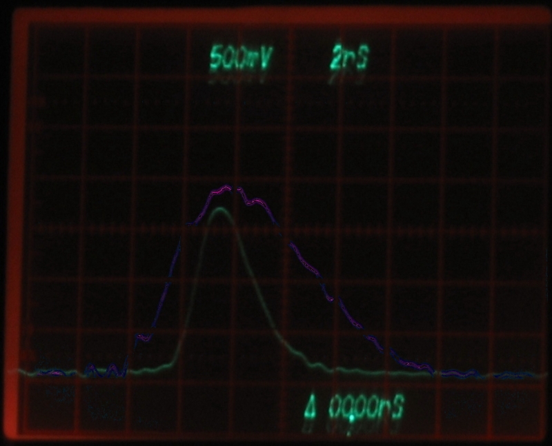
For the sake of comparison, here is the nitrogen
laser’s output (purple) superimposed on the dye
laser’s output (green). Because the triggering was
the same for both of the original photos (it was derived
from the output of the photodiode), the dye laser pulse
was originally too far to the left. I have moved it, but
of course I had to guess at where to place it, so you
should take this image with a grain or two of salt. I
had to trace over both photos by hand, btw, because they
were not bright enough to select with the Gimp; this
accounts for the slightly jagged look.
(Here, if anyone cares, is an earlier version, for which
I also tweaked the timing:
I suspect that the dye trace [again, green] is still a
bit too far to the left in this photo.)
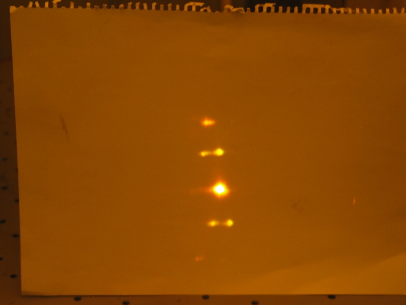
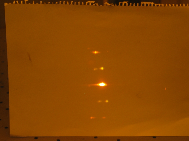
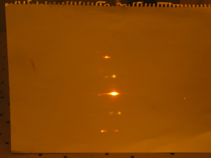
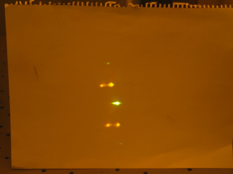
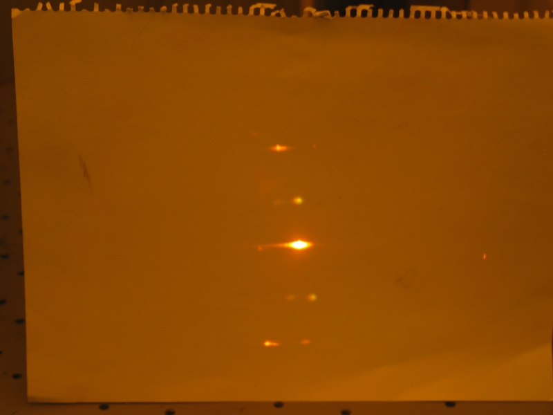
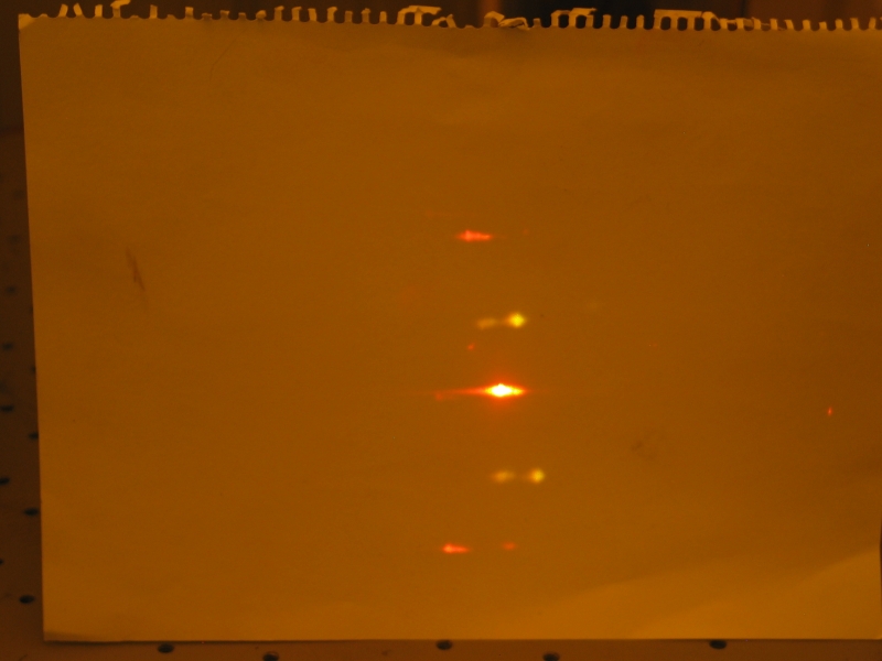
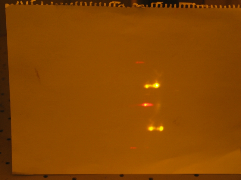
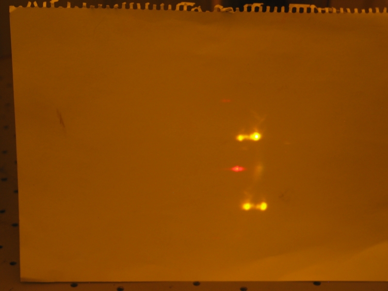
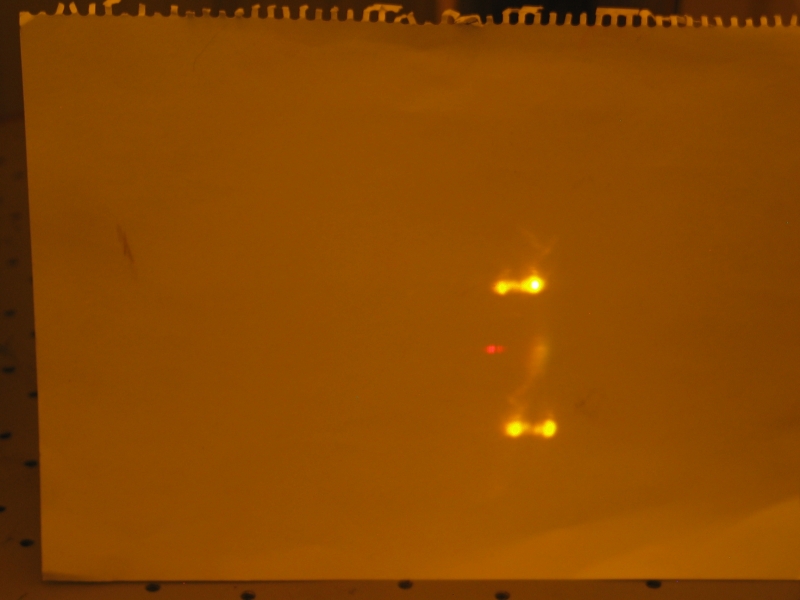
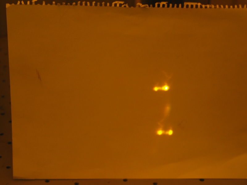
The next set of photos illustrates vertical alignment and
misalignment. You can see the tuned spot most sharply in the
middle image, where the vertical axes of the grating and the
mirror are aligned well with each other and with the pumped
stripe on the cuvette. (The dye here is Rhodamine 6G.)
You can see that when the mirror and the grating are aligned
best, the untuned spots are dimmest. This will be visible
again in the tuning curve below.
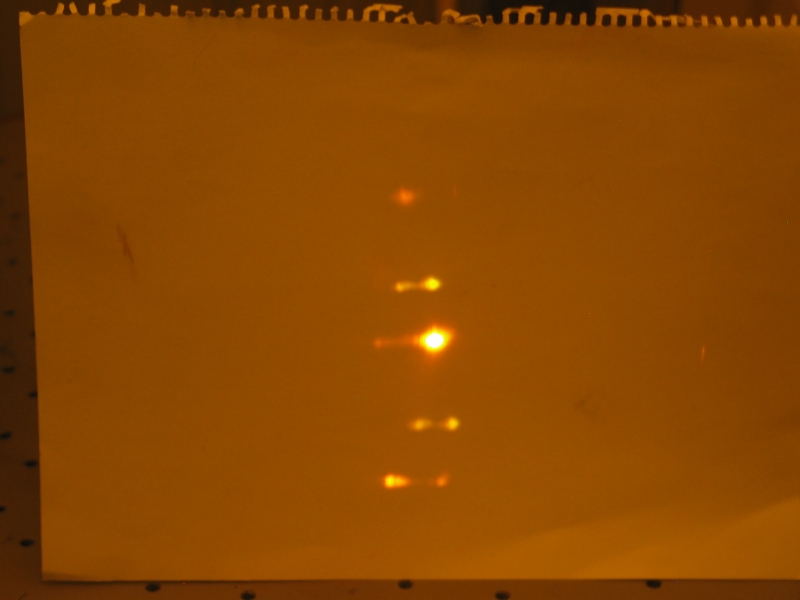
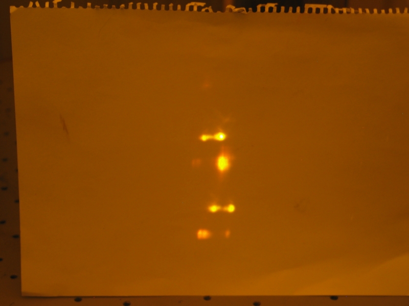
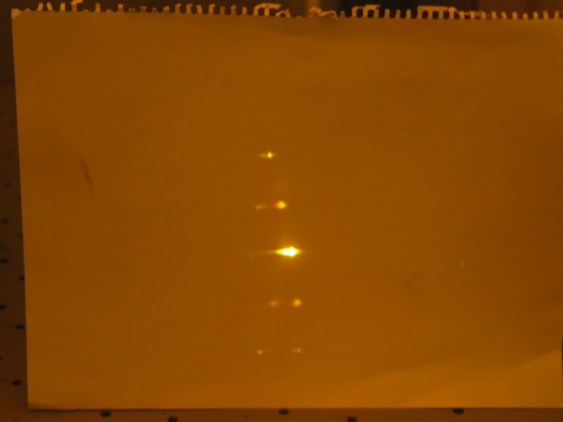
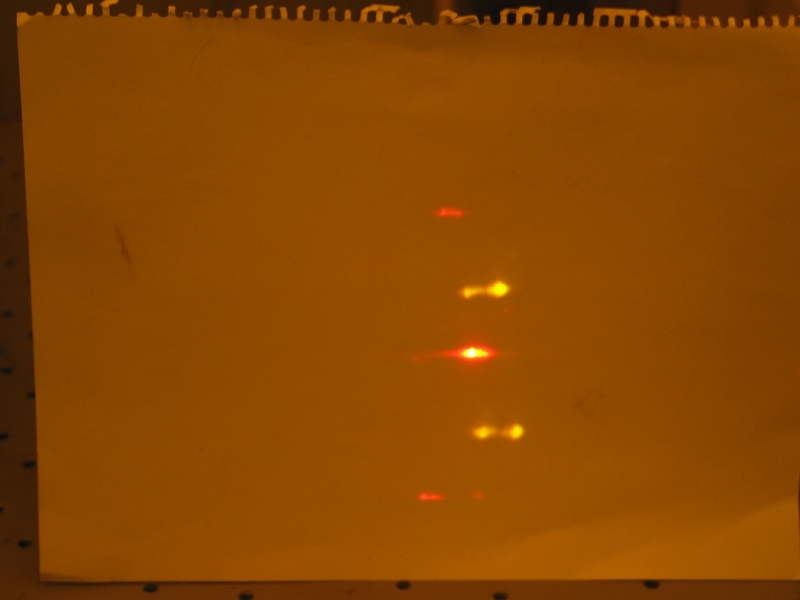
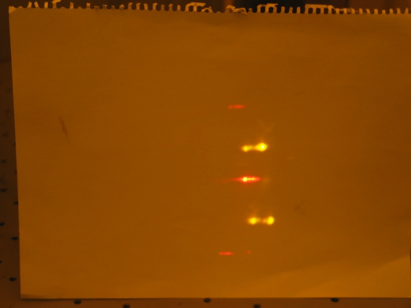
Here’s a visual tuning curve for Rhodamine 6G:
As mentioned above, you can see that at the peak of the
tuning range, shown in the 4th through 6th photos, the
untuned beams above and below the tuned beam (which are from
reflections off the walls of the cuvette) are much dimmer
than they are at the ends of the tuning range. If I built a
setup that provided even more feedback the effect would be
stronger, and the tuning range would be at least slightly
broader.
Note, also, that the relative position of the tuned beam
changes with respect to the positions of the untuned beams.
This and other effects make it necessary to adjust the
alignment of the grating as I tune, and sometimes makes it
necessary to tweak the horizontal alignment of the mirror
slightly in order to get maximum output.
A final note, added in proof (as it were) on
10 June, 2005: I went to take this laser off
the bench so I could put a different one into
place (see
this page if you want more info about that
project), and noticed that the nitrogen hose
was lying on the floor. When I put it into the
port on the laser, it fell right back out again.
This strongly suggested that I’d been running
the laser on air. (I was wondering why I got best
operation at the lowest pressure the control
electronics would allow!)
I put the hose in and tightened it up. Sure
enough, I now get best operation around 45 Torr
rather than 32, and best operation with Fluorescein
appears significantly brighter by eye than it did
when I was using air, so I’m probably getting two
or three times as much power out as I was. Such
is life. (It pays to notice these things early,
rather than late, but it’s certainly better to
notice them than not.)
To the top of the LASERs section
To the top of this [updated] mirror
To my current research homepage
Email: a@b.com, where you can replace a with my first name
(just jon, only 3 letters, no “h”) and b with joss.
Phone: +1 240 604 4495.
Last modified: Tue May 9 12:50:33 EDT 2017

Tuning I: Setup and Adjustments


Tuning II: Results
The Joss Research Institute
Contact Information:

