(First, a brief note: there is apparently an article on Yohen Tenmoku in a newish Japanese pottery magazine, which covers the work of no fewer than ten artists. I am trying to get my hands on a copy.)
[Note, added in proof, late 2008: I have a copy, and a Japanese friend is trying to translate the article for me.]
Some time ago, we acquired a smallish Molectron nitrogen laser on eBay. It languished for a while, sitting on a “lasers we haven’t gotten to yet” shelf, but a couple days ago I made some space on the bench and set it there.
There was something rattling around loose in it, and I had to open it up anyway, to get a sense of the guts; the loose object proved to be a broken cable tie, which I removed.
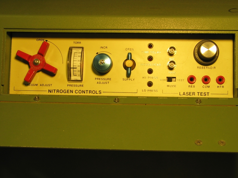
Here’s the control panel of the device. Sorry about the lighting — I left the camera’s white balance set to “cloudy” through most of this, to get the best color rendition of the output.
You’ll notice that the pressure is just over 30 Torr. That’s about as low as I can get it and still run the laser; the “Lo Press” light blinks every time the laser fires.
This afternoon I got the vacuum connection cleaned up a bit with hose clamps (the laser takes a rather rude hose, which was leaky), and tried powering it up. It seems to work quite nicely.
This evening I aligned the mirror as well as I could, and then put the big focusing mirror out in front. I now have the best tuning I’ve seen so far, using R6G: it’s quite smooth all the way from a fairly rich orange to a somewhat yellowy green, with almost no ASE.
I need to find my spare instrumentation amp chip before I’ll be able to measure the pulse energy; but it superficially appears entirely nominal. I’d guess 1mJ or so, roughly comparable to the output of the LN-1000.
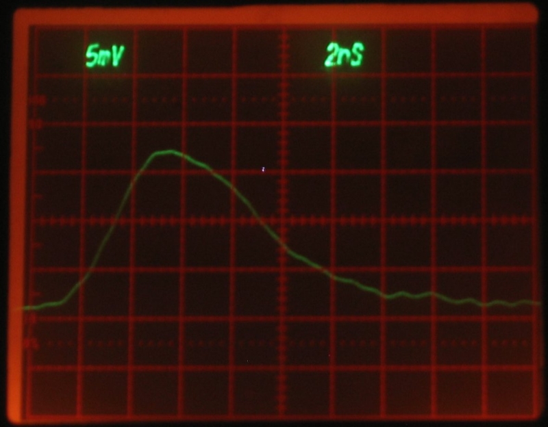
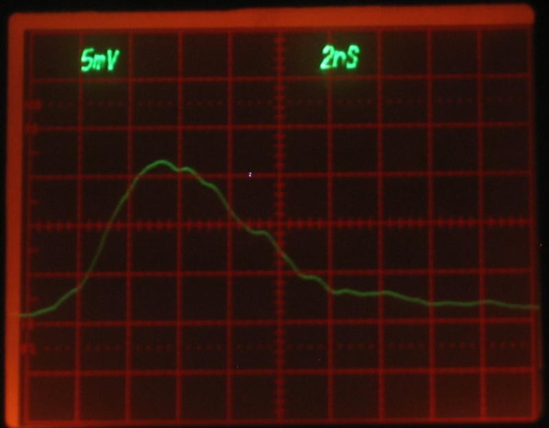
Here are two photos from the Tek 7104 scope, taken on June 3, 2005. I am using a very nice photodiode that Howard Davidson sent me, a while back, which I’m powering with half a dozen 9-V batteries from the grocery store — I figured that would avoid any noise that an ordinary power supply might produce or pick up. I think it’s nominally 47 Ω, so I ran the scope end of the coax into a 50-Ω terminator. I was using a reasonable but not outstanding vertical amp (probably a 7A26); if I can get the scope running again (it blasted its screen to full brightness, and responded only to the power switch) I will try this again with a 7A19, which is much faster.
Although I have no control over the operating voltage, the controls do permit adjustment of the pressure, and I find that I appear to get best operation at the lowest setting it will allow. (It has overpressure and underpressure trip points, and automatically shuts down.)
Here’s the setup, viewed from above. Notice that the rear reflector is very nearly touching the dye cuvette (the white rectangle with the pinkish junk on it is the teflon cap of the cuvette) —
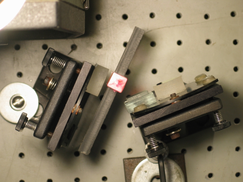
Here’s a closeup of the cuvette (filled with Rhodamine 6G in 91% isopropanol), with the nitrogen beam hitting it:
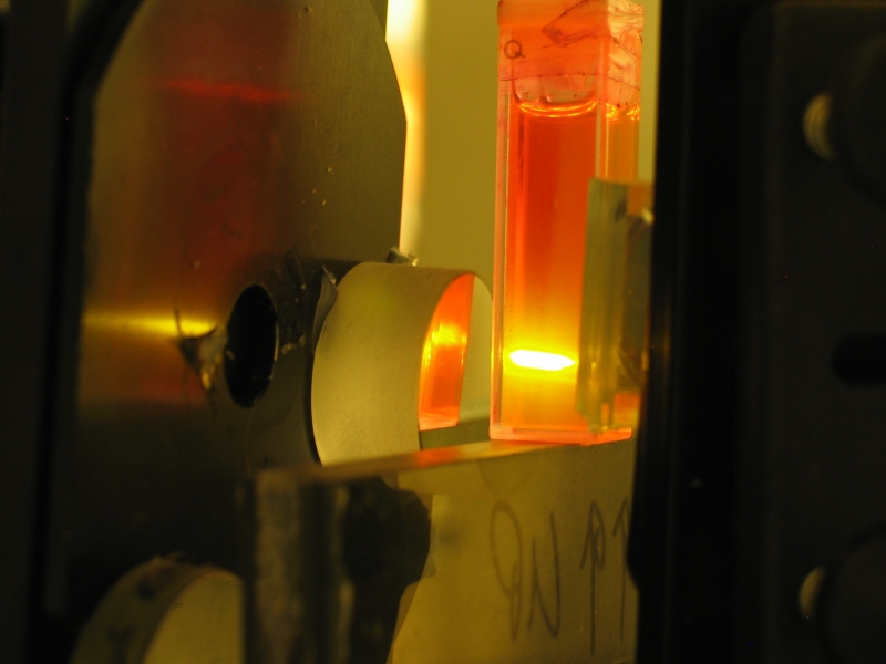
As you can see, the nitrogen beam forms a line across the front of the cuvette, and that line is slightly tilted with respect to the cuvette’s vertical axis. This is a side-effect of the fact that I’m using an angled mirror to focus the beam, rather than an inline lens; it lets me stand the cuvette up more or less vertically, but it makes aligning the mirror (about in the middle of the photo) and the grating (on the right, partly obscuring the cuvette) a real pain in the butt.
Here’s a tuning tour:
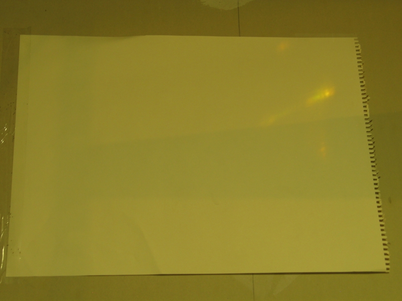
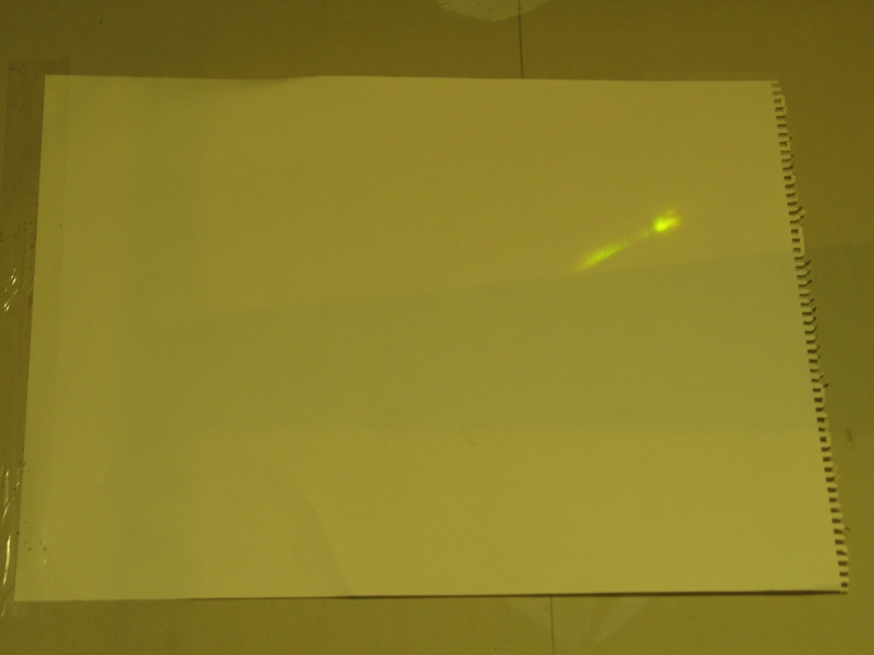
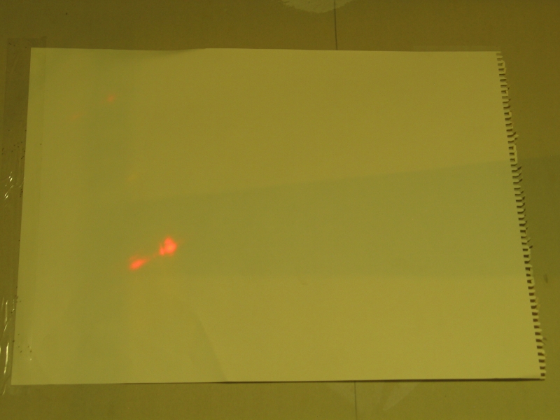
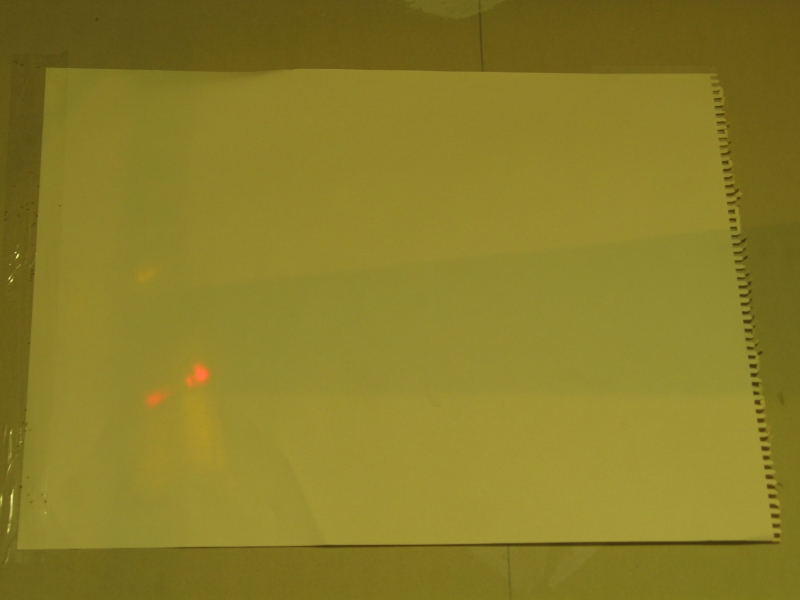
Notice that at both the long and short ends of the tuning range, the beam dissolves into lasing off the cuvette walls and possibly a wee bit of superfluorescence. You can tell the difference -- where there is superfluorescence, it should appear as a diffuse bright vertical band, which is what I believe you can see below and through the orange in the last photo. Lasing off the cuvette walls will show up as pairs or multiplets of bright spots [or short vertical lines], more easily visible in the first photo. In either case, it will be at the untuned color that the dye characteristically lases at, given the solvent, concentration, and pathlength. (Mind you, because I’m reflecting this up from the bench to the wall, “vertical” is a relative term.)
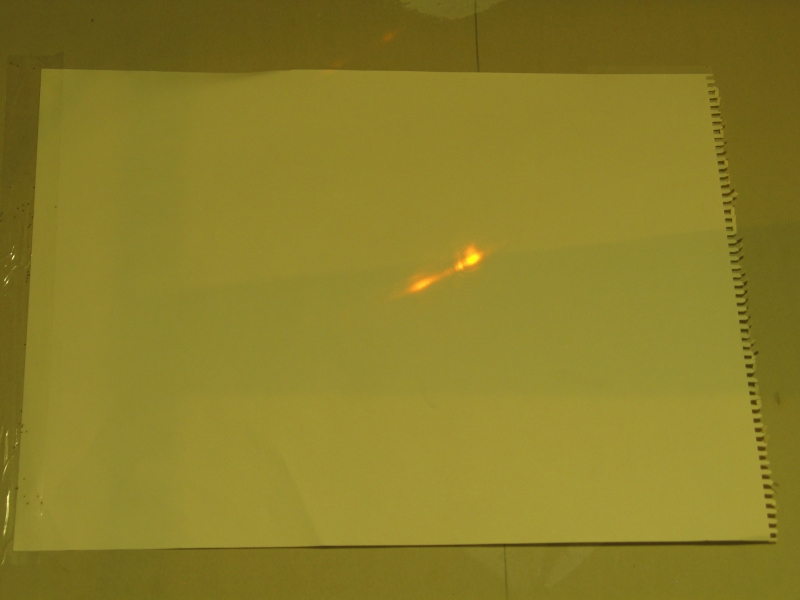
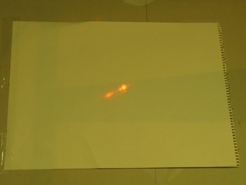
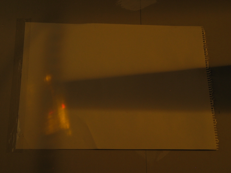
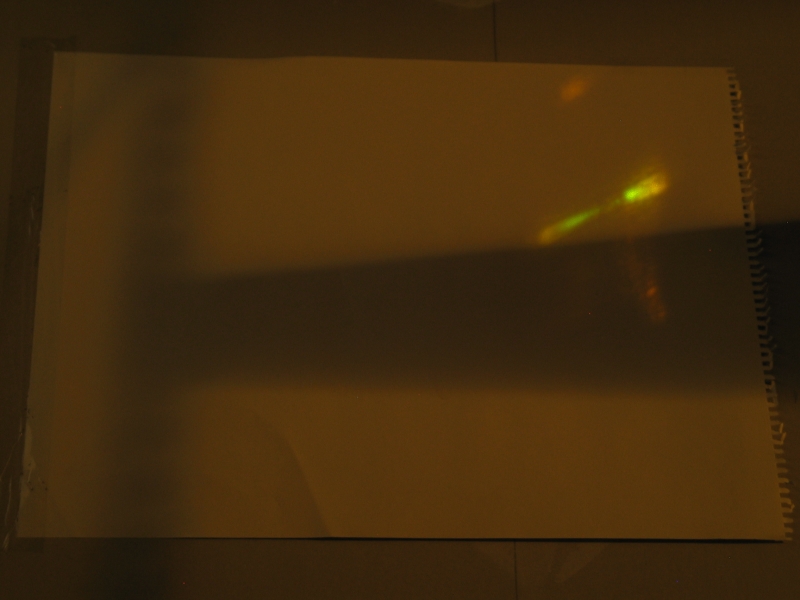
Sorry the background on those is so bright, btw. At some point I will try to retake them with a little less roomlight, so the laser output is a bit easier to make out. Meanwhile, here are two [admittedly lousy] “end of the line” shots, to give you a better sense of the tuned output disappearing into a welter of untuned yellow:
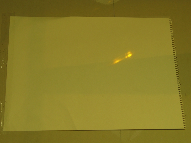
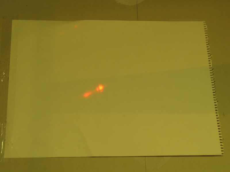
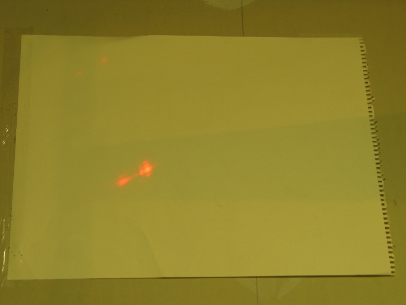
Here's what happens when I align my cuvette closely (perhaps a bit too closely) to the beam:
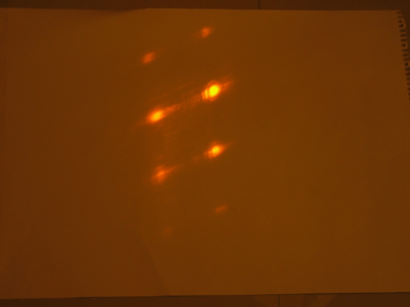
As you can see, I get multiple bounces off the cuvette
walls and the mirror (or possibly the grating, though
the mirror it more likely) resulting in multiple output
beams.
Email: a@b.com, where you can replace a with my first name (only 3 letters, just jon, no “h”) and b with joss.
My phone number is +1 240 604 4495.
Last modified: Fri Sep 2 13:53:13 EDT 2011