Reinhold Platz worked for Anthony Fokker. I am very hazy on the details, but there is some information available if you search it out; suffice it to say that Platz was a designer and builder, but not quite an engineer — he was great at coming up with ways to accomplish things when the engineers were stumped; quite intuitive, only moderately mathematical. I believe he started as a welder, and was eventually put in charge of assembly at one of Fokker’s plants; but please take that with a grain of salt, as this page is about his glider, not his career. (There is some history, as well as some information about the glider, on one of the Oz Report pages, and various controversy on any number of Web pages about exactly how large his role as a designer really was.)
Be that as it may, both Platz and Fokker were sailing enthusiasts. Some time around 1921, Platz apparently had An Interesting Notion: the sail and jib of a boat are very much like a wing and a canard-type control surface. Can you turn them sidewise, do a mirror reflection for symmetry, and get a flying machine? The answer, as you can see on the Web in photos from 1922 and 1923, is very clearly “Yes.” It isn’t efficient in today’s terms, but it is certainly interesting.
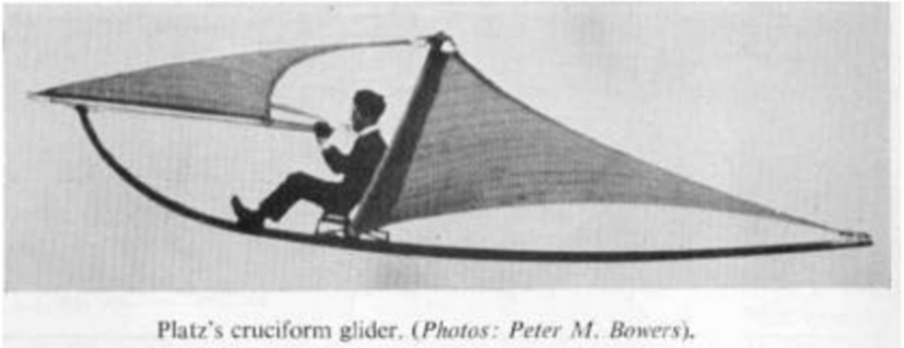
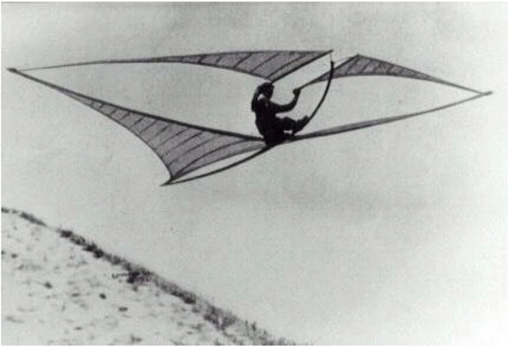
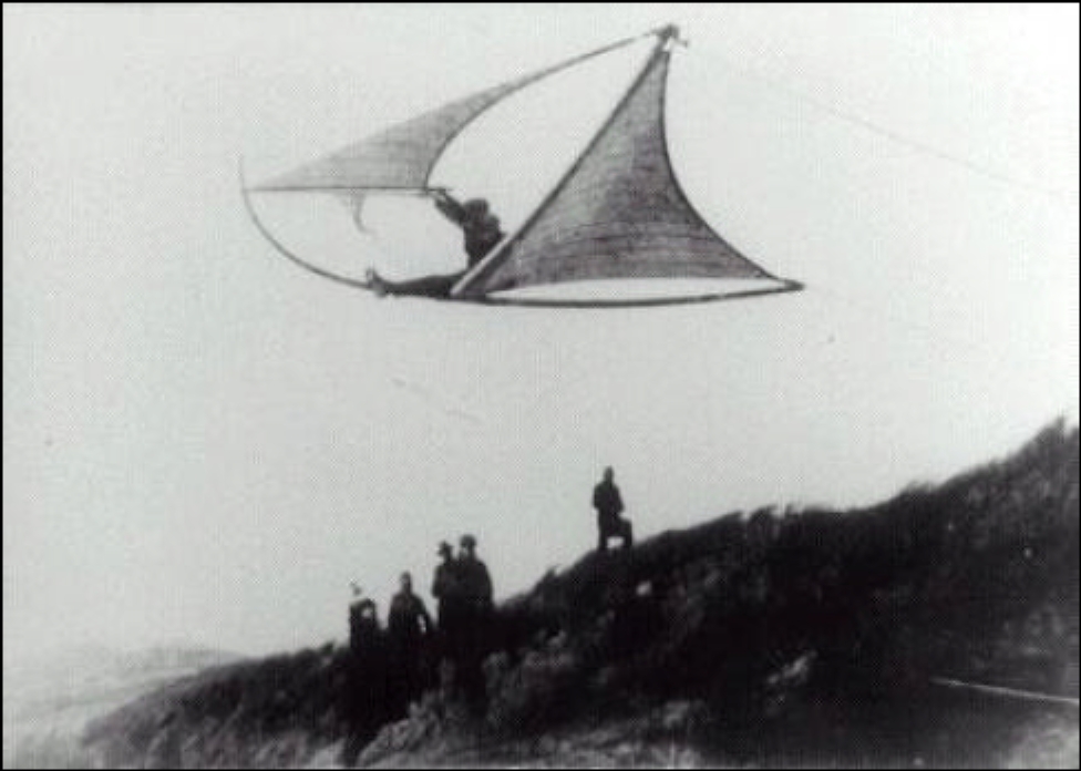
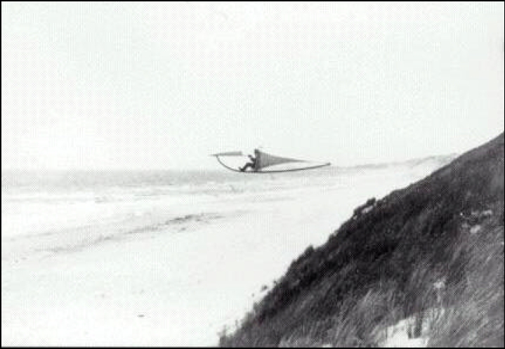
Most of the photos I’ve found so far are too small or indistinct to be of much use; here are about the best two:
(You can click the small images for larger versions.)
Even with nothing more than mediocre photos and a little bit of text, it is possible to get a fair sense of the design. To be sure, it’s a bit wacko; but the photos I’ve seen, with the exception of this next one, do show the machines (and there were clearly several of them) in the air.
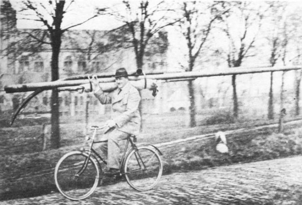
As you can see, it’s quite portable; the weight was reported to be about 40 kg. That may possibly be Platz himself on the bike, btw.
I have been doing a bit of thinking about flying wings,
and the Platz-Gleiter seemed to me to be a cute thing to
make a model of. Various people have, indeed, done this,
with varying degrees of success; the difference for me is
first the fact that I have zip experience, and second
the fact that I wanted to motorize it. (Someone did build
a motorized one, but it was too small to carry the weight
of the motor he was using, and he was unable to get good
control, so he set it aside. One person seems to have
built
a radio-controlled model, not motorized,
and lots of people have built kites. These are similar to
the Marconi kite.)
I note a few things, which I will detail here...
The next issue is one of control. You need to be able to raise and lower both control rods, and you need to be able to do them together or separately. Because my (borrowed) transmitter is rather rudimentary and doesn’t offer any mixing functions, I worked out what is apparently a very standard way of mixing servos mechanically. It involves a hinged platform and two servos — one servo, on the under side, drives the entire platform up and down for what is effectively equivalent to the elevator control on a regular airplane; the other, which sits on top, drives the pushrods in a push-pull configuration for steering. (I will eventually diagram this.)
I’m still thinking about hinges and fastenings, and also about how to keep the sail from tearing; I will report further as I make progress.
Meanwhile, let’s try to get some sense of size. Here’s a marked-up version of the first photo, or actually of the cruder version of it that is easier to find on the Web...
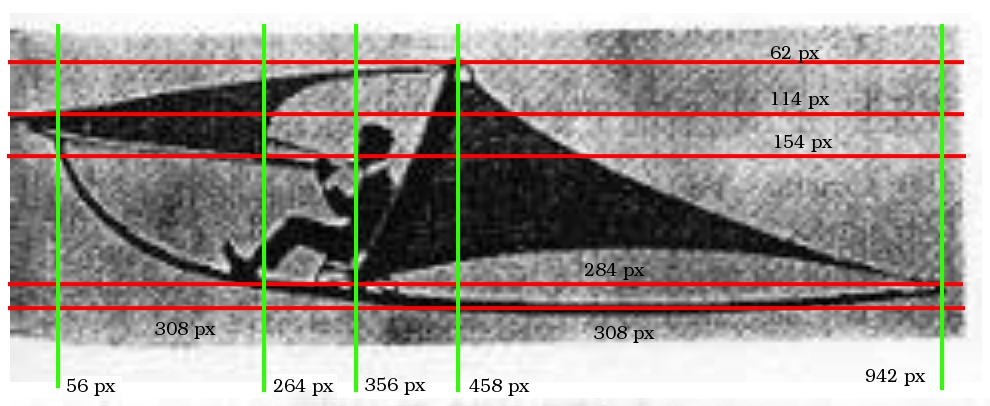
If we figure that Platz (who is apparently driving the bus here) was of nominal stature, 170 pixels (284 minus 114) should be about 3.5 feet, or perhaps a bit less because the seat of the chair is fairly low. (I just checked, and when I’m sitting in a similar position, the top of my head is about 1 meter off the deck.) We’re then looking at 48-50 px/ft, which I think we’ll ease to 50 for convenience.
The length of the main boom is about 18'; canard root chord is maybe 5', with another 4.5' or so of sweepback to reach the wingtips (though not quite all of that is actually spar, as you can see in the first photo); the canards are attached to the pivot just over a foot back from their tips. Dihedral appears to be about 3 to 3.5', allowing for parallax (see the other photo — the wingtips are at roughly the same height as Platz’s head). Wing chord at the root is about 12'; this suggests a 24' span, ignoring the dihedral.
I appear to be planning my device at 1.5in/ft scale, which
seems quite reasonable. Mind you, the original was certainly
done in meters rather than feet; but I hardly think it matters
much for the purposes I have in mind here.
Platz reportedly tried a paper model first, and I think I will do the same. More as it happens...
(24 November, 2005)
Version 0.01 fails: I used a Priority Mail box, which is thin corrugated cardboard, but I went for 12" span, which is too small for that thickness. I have another box, even thinner corrugated board, and I am thinking about going for 20" span from that; I can’t get any bigger because the box is too small. In fact, because of the positioning of a cutout, one of the canards is going to have a bite out of its trailing edge. We Shall See whether this proves viable...
(The Following Night...)
Version 0.02 sorta almost flies, now that I have glued a 1/8" hex key onto the front as a balance weight. This one is bigger than last night’s, (wingspan probably 18") and is made of thinner corrugated cardboard. It appears to be incredibly sensitive about control surface angle. I haven’t tried turning it yet; the longest flight so far was only about 6 feet, plus a bit of slide after touchdown. I can see that it is going to take me some serious tweaking and testing before I’ll be able to fly a larger model, but at least I begin to have some sense of the behavior.
Unfortunately, my camera is in the shop, so I don’t have any pictures; but I have so far refrained from destroying the thing utterly, and I hope to be able to photograph it later.
Meanwhile, I am thinking about whether I should perhaps use a thicker piece of spruce for the boom and spar on the next version, and I’m also thinking about kite material (ripstop nylon?) for the canards and the sail.
(Saturday, 26 November, 2005)
I managed to get some spar and boom material at one of the local hobby stores, but neither place I tried has any ripstop nylon. The guy I talked to at the one here in town suggested that I check out G Street Fabrics, a truly splendid notion — even if they don’t have it, they’re always worth a visit.
Meanwhile, I have succeeded in steaming and bending
two 1/8"-x-1/4" spruce bars, which I intend to laminate
together to make the boom. (Well, I sorta succeeded: I
did some damage, and the bend is not entirely smooth.
I think they’ll do for a prototype, though.)
(Tuesday, 29 November, 2005)
I now have a laminated boom (2 pieces of 1/8" x 1/4" x 36"
spruce, epoxied together) and spar (1/16" x 1/4" x 30"
spruce epoxied onto 1/8" x 1/4" x 36" spruce) and, courtesy
“Big Mike” Nicewonger, I have a 280-size motor,
a prop, and a yard of ripstop nylon, so it won't be long.
Have to go find the best way to deal with the nylon; I
don't want to glue it to the spar with CA, because there is
significant flexure, and CA won't handle that very well.
Please see
the next page in this set.
Email: a@b.com, where you can replace a with my first name (jon, only 3 letters, no “h”) and b with joss.
My phone number is +1 240 604 4495.
Last modified: Mon Jul 7 19:52:34 EDT 2014