(27 December, 2005, ff)
We have acquired one of these units, often referred to
as “M-60” lasers, though that is not
actually the correct designation for them (I believe
that they are mostly designated AN/VVS-1), from
The Highly Esteemed Nortius Maximus.
It is in very nice condition, though lacking electronics.
My hope is to bring it up, first with the Q-switch
held at the firing position, and later with the switch
running. Here are some photos, for reference.
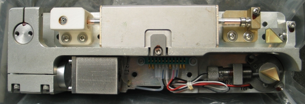
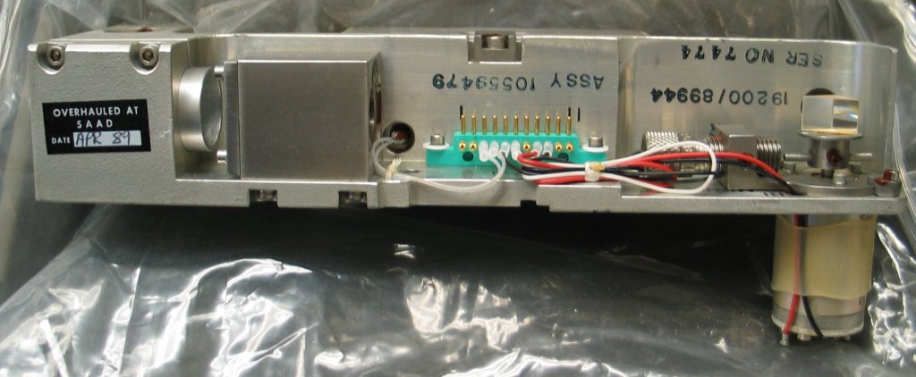
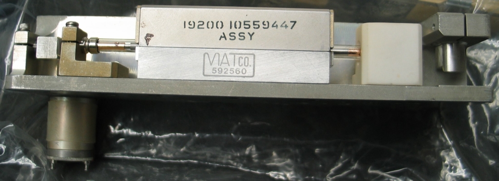
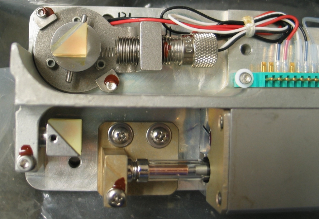
First, top and side views of the entire device:
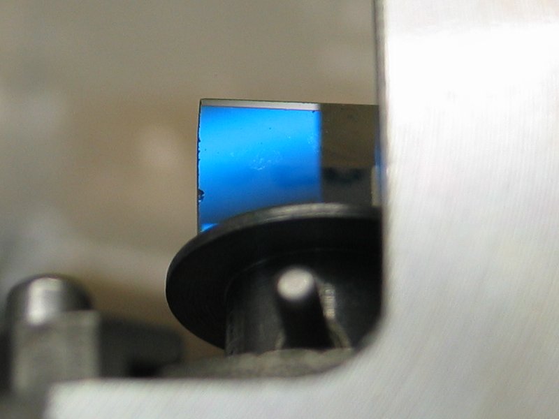
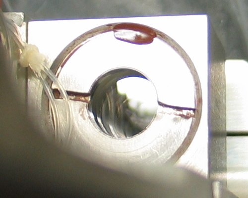
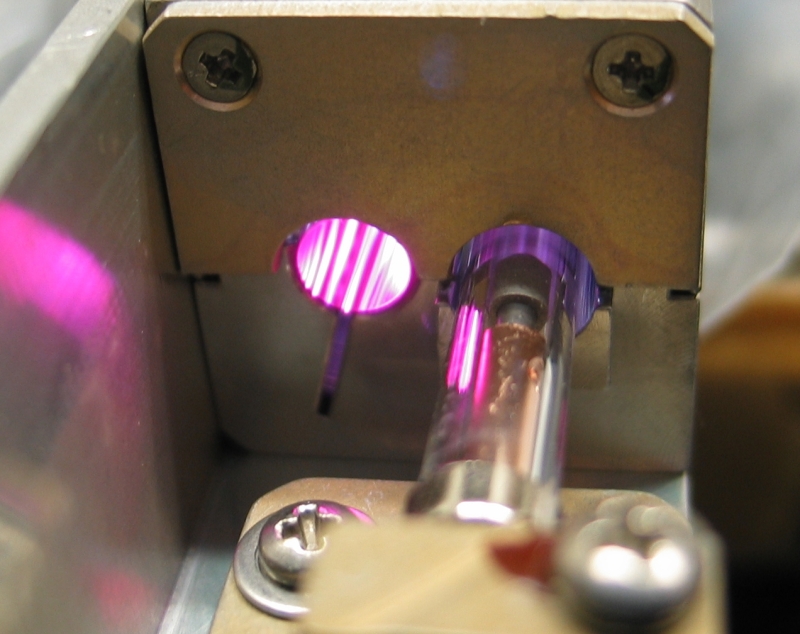
Next the rear reflector (a prism) seen from behind, with the end of the ruby rod partly visible in the background and a bit of the etalon visible on the right side, through the output port (we do not have the beam-expander telescope); then the Q-switch (upper prism) in firing position, so that it faces the etalon and the other prism (which, in turn, faces the ruby rod); and the rear face of the Q-switch prism, which turns out to be coated. In fact, all three faces of the Q-switch are coated.
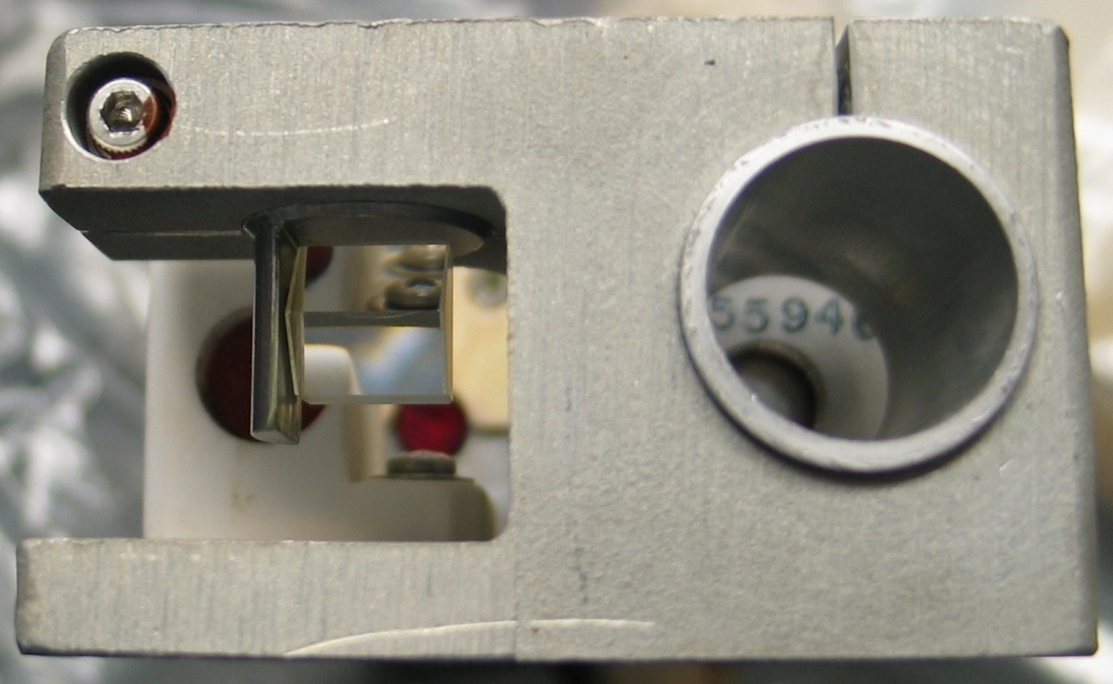
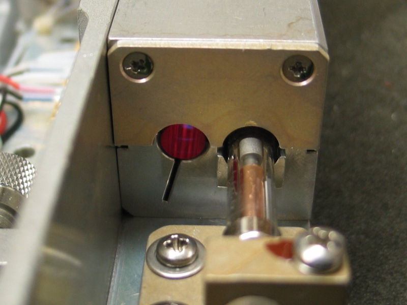
A look at light bouncing off the etalon (which is bright enough to make me think that the etalon is constructed of fused silica), then two views of the ruby. For the second of these I put a white LED behind the rod so you can see the color better.
(31 December, 2005)
A special note of thanks here to Sam Goldwasser, who has characterized the etalon that is used as an output coupler in this laser. Sam’s Laser FAQ is a huge and comprehensive resource for anyone who is interested in building lasers, working with existing lasers of various sorts, or getting some understanding of what lasers are and how they operate.
This laser was built about 20 years ago, and it has some features that relate to the state of laser technology at the time. For example, instead of dielectric-coated mirrors, it uses a simple prism as a rear reflector, and an uncoated Fabry-Perot etalon as an output coupler. It also uses a rotating prism as a Q-switch; a passive Q-switch would not work well in this application, because passively Q-switched lasers often tend to emit more than one pulse per firing, which is counterproductive in a rangefinder device. In addition, the rotating prism creates its own timing pulse, which not only sets off the flashlamp but also establishes base timing for rangefinding. That isn’t relevant to me, but certainly is to the design.
Some DIY folks either add a second output coupler, which reduces the threshold, or replace the etalon with a standard output coupler. Because my interest with this laser is mostly in holography, I will probably add a second output coupler: the etalon increases the coherence length, which is extremely desirable in ruby applications of the ordinary sort. I would like to extract about 60 mJ per pulse if I can, as that is roughly what I expect to require in order to expose a 4x5 inch plate.
The pulsewidth is nominally 40 nsec, which is short enough to allow photography of living subjects. Unfortunately, ruby emits a lousy wavelength for taking pictures of people. We are apparently translucent enough at ~700 nm that we look rather waxy and unreal. Cats, dogs, mice, and the like, however, should be just fine, perhaps excepting their noses and the pads of their feet.
In addition, the usual constraints about vibration that apply with CW lasers are simply irrelevant. If you have ever tried to make holograms with a HeNe laser, you will know just how convenient this is. (Here, however, I should note that anyone on “the plateau” in Issaquah, Washington is truly blessed. When I lived there, all I had to do was drop a piece of chipboard on the carpet in the basement, and set everything up on it. As long as I waited for the air to settle after the furnace turned off, which took perhaps a minute or two, I got beautiful exposures at least a minute long. No stabilization, no cushions, no nothing, just the floor. I now live about 35 feet from active railroad tracks, so it’s a different world.)
Be that as it may, no ordinary vibration is going to give us trouble during a 40-nsec exposure. For those who haven’t been through this yet, let’s do the numbers:
The wavelength we’re using is about 0.8 μmeter, give or take a bit, and if any two parts of the setup (object, plate, optics) move more than about 1/8 of one wavelength during the exposure, we don’t get a decent ’gram. (This is not like photography, where only the moving object is blurry; in holography you are recording the phase of the light, and the entire image tends to suffer.)
So. Our exposure is 40 nsec long; how fast can something be going if it gets to move less than 0.1 μmeter in that time? Clearly, 1/40th of 0.1 μmeter per nsec, right? Well, that’s 1/40th of 0.1 millimeter per μsec, which is 1/40th of 0.1 meter per millisecond, which is 1/40th of 0.1 kilometer per second. 0.1 km is 100 meters, and 1/40th of that is 2.5 meters, so nothing in the setup can be moving more than 2.5 m/sec. The actual wavelength is slightly shorter, so 2.5 m/sec is actually a bit loose, but it’s close enough for folk music. You can easily take a photograph of an ordinary bullet in flight with a 40-nsec flash, but you aren’t going to make a hologram of one.
On the other hand, your cat can be washing itself and you’ll still get a decent image. People, if you are willing to have pictures that look like they came from a wax museum, can be waving ‘hi’ to their moms. If your dog (or cat, or bird) is kicking itself in the head with sufficient vigor, or if your tiny trebuchet is in the middle of flinging a pebble at you when you push the button, you may get a gray blur instead of a hologram; but short of that level of motion you should be okay.
Back to optics: they have to be very clean, because a Q-switched pulse is considerably more powerful than an unswitched pulse, all other things being equal. These lasers are rated to put out roughly 1.25 MW, and the rod is about 6 mm across, so the optics must withstand something like 4.5 Megawatts per square centimeter. That’s not actually too horrendous in terms of the capabilities of good optics that are designed for pulsed use; but it is certainly substantial. Any dirt that gets in the way will be blasted into plasma, and will probably either damage the coatings or surfaces, or turn into something nasty that is stuck very firmly onto the coating. Before I actually use this laser with its Q-switch running I will build a nice cover for it, to keep the dust out. (On careful inspection, I can see some probable damage on one of the faces of the Q-switch prism. We’ll just have to see whether it still works properly.)
Speaking of Q-switch, the little DC motor that rotates
the Q-switch takes about 20 volts, and runs at about
30,000 RPM. In actual operation the motor was turned on
and allowed to come up to speed, which typically takes
less than 1/10 of a second, after which the laser was
triggered, and then the motor was turned off again. This
protocol avoids putting excessive wear on the bearings
and brushes of the motor, and is A Good Idea. I
wouldn’t know where to look for a replacement motor,
and I’d expect it to be somewhat expensive. It is
possible that some of the motors currently in use in
radio-controlled model airplanes would work, but fitting
them to the laser is likely to be a nontrivial exercise.
OTOH, if you are building something of this sort from
scratch, you could consider one of the new brushless R/C
motors — they are quite good. OTTH, balancing a
prism on a table so that you can spin it at 30,000 RPM
without tearing your motor to shreds and flinging tiny
daggers of glass all over the room is a seriously
nontrivial exercise, and you may want to consider
alternative Q-switching methods.
I have built a 2-mesh PFN to run the flashlamp. Here (please excuse the ASCII-pic) is a rough diagram of it:
       GND          +HV
        O            O
        |            |
        |     ||     |
        +-----||-----+
        |     ||     |
        |            |
        |     ||     |
        +-----||-----+   Bank 1, 3x 50 microfarad
        |     ||     |
        |            |
        |     ||     |
        +-----||-----+
        |     ||     |
        |            |
        |            D
        |            D
        |            D
        |            D  Inductor 1
        |            D
        |            D
        |            D
        |            |
        |     ||     |
        +-----||-----+
        |     ||     |
        |            |
        |     ||     |
        +-----||-----+   Bank 2, 3x 50 microfarad
        |     ||     |
        |            |
        |     ||     |
        +-----||-----+
        |     ||     |
        |            |
        |            |
        +-----||-----+   Snubber/Bypass, 2.7 nf
        |            |
        |            |
        |            D  Inductor 2
        |            D              o Trigger
        |            D               \
        |            D C--------------|<---+
        |            D C                   |
        |            D C-----+---||---+----+
        |            D       |        |
        |            D      GND      + 750V
        |            |
        |            |
        O            O
     CHASSIS        LAMP
Each of the inductors is about 65 turns of #10 solid wire; “CCC” is the primary of the trigger transformer, 3 turns of #14 stranded, wound very wide so that it takes up the entire length of the inductor. (The inductor functions as the secondary.) Voltages being what they are, I may change out the #14 stranded for some actual HV wire, later on. I have added a “doorknob” capacitor, 2.7 nf, as a bypass or snubber across the output end of Bank 2, to prevent any possible unpleasantness in the event that the large energy storage capacitors are not quite fast enough to dissipate the trigger pulse safely. I would seriously prefer not to puncture the dielectric in them.
I’ve indicated an SCR as the trigger switch and 750 V as the trigger primary supply voltage. It may be necessary to add a snubber diode, though frankly the SCR I expect to use is gross overkill for this application. Unfortunately, I don’t have the SCR on hand yet, and I am operating at lower voltage with a trashy switch for initial testing.
Milan Karakas points out that the fact that the inductor is air-core is working against me; he thinks that I may not get the full turns ratio of voltage multiplication. This should be fairly easy to test, and I will be checking it.
(30 December, 2005)
Here’s a view of the PFN, with a detail of the trigger transformer section after I changed the primary to 5 turns:
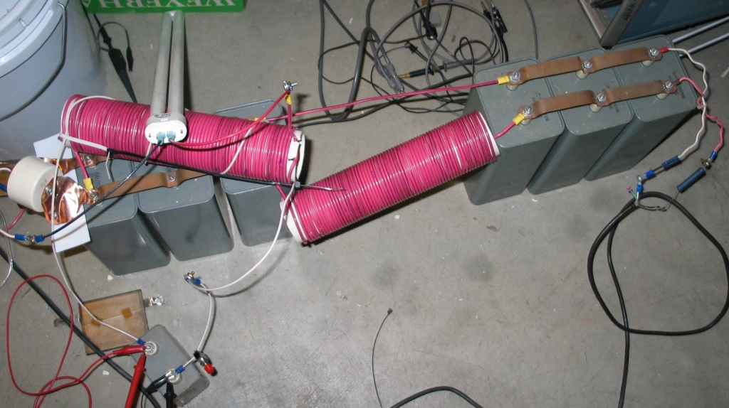
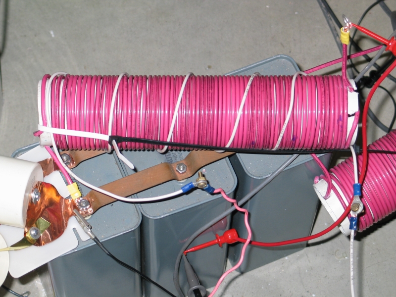
I have laid the output inductor (which is also the trigger transformer) over on top of the second bank of capacitors, for convenience in attaching it to the fluorescent tube. Later on, for actual use, the PFN will probably be folded into an “S” shape for compactness, and I may post another photo.
(31 December, 2005, and Happy New Year, 2006)
We are working on acquiring reasonable power supplies; in the meanwhile, I am working on jury-rigging unreasonable ones.
(Here’s one way to make a ~1-kV power supply if you are in a hurry and are largely in “scrap-heap” mode.)
I am probably going to build two of these, one to charge the main store, and one for the trigger supply. There is a good chance that the one for the main store will use a microwave-oven transformer, for speed: oil-burner transformers will deliver only minuscule currents at 1/10 to 1/5 of their rated input voltage. (They should be viable for testing purposes, though, and for powering trigger circuits that happen to require high input voltages.)
[Note, added later: That is exactly what I did.]
I will point out here that regardless of how you do it, you are charging hefty capacitors to lethal voltages, so all of the usual safety precautions are decidedly in order.
For convenience, if you don’t want to go read the entire Klugeworks page, here is the schematic of the main supply:
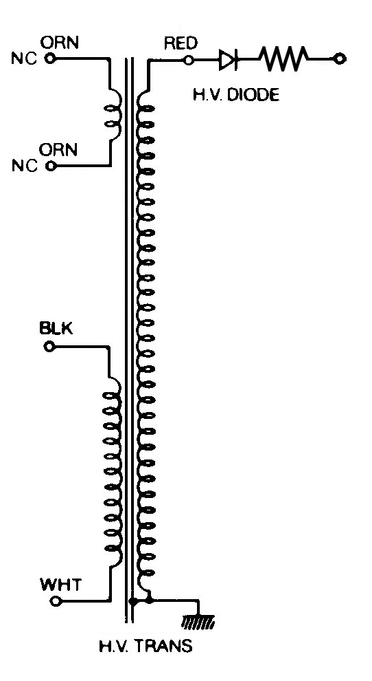
(Input at the left, on “BLK” and “WHT”, which are actually just metal tabs — the colors are those of the wires that used to be plugged onto them in the oven. In fact, the HV output, which is labelled “RED”, is also just a metal tab; happens to have a red wire plugged onto it. The two “ORN” wires, however, which powered the filament of the magnetron in the oven, are actual orange wires. So go figure.)
Next, the Variac™ is connected to this, which means I no longer have it to power the oil-burner transformer, and I will run that off one of the little 20V AC supplies I got yesterday at the thrift unless it turns out that I need very high voltage on the primary of the trigger transformer. I am going to remove the fluorescent tube and put an actual flashlamp on the output of the PFN, to get conditions that are more realistic. There is also the delicate question of whether the fluorescent bulb would survive a 100-joule pulse if I brought the PFN up to a reasonable voltage, or even whether it might self-flash before I got a chance to try my trigger generator on it.
(04 January, 2006)
I was unable to get any light from the flashlamp, so today I read some PDFs about transformers on the Web and became somewhat discouraged. I had enough trouble with integrals in 1970; I would really rather not be obliged to go and relearn calculus now.
This evening I took a powdered-iron toroid and wrapped 25 turns of #12 solid copper on it. Then I put a 2-turn primary on, put the flashlamp across the secondary (no connection to the PFN yet) and tried to get some sort of light out of the lamp. No joy.
It then occurred to me that this is a well-used lamp, and I should really check it to see whether it’s actually still a flashlamp at all. I put it on my little voltage-doubling-circuit tester, and what do you know? I have to crank the 20 kV power supply up to about 63% before the blasted thing lights up. That’s noticeably over 12 kV direct, and probably 18 or 20 kV with the additive effect of the inversion. No ruddy wonder I haven’t been able to get the thing to light up with my puny trigger circuits!
I guess my next step is to test flashlamps until I find something that will trigger at a more reasonable voltage, and then put that across the new transformer. If it works, I get to try it across the original air-core device, though I have somewhat less hope there. In the meanwhile, I may try the fluorescent lamp across the new transformer just for yucks.
(Early AM, 05 January, 2006)
I have now succeeded in making a series of low-voltage measurements with my trusty 7904. Getting it to trigger was a bit of a trial — I think something is badly out of adjustment — but I eventually did get triggering, and I have a microswitch to set the thing off with, and the results are rather unsettling. I will try to take photos of the scope traces after I sleep; it’s too late at night to do it now.
I have about 14 VDC on the capacitor, which is 10 VAC with a half-wave rectifier on it. I have not actually checked this voltage, but I will be able to do so tomorrow. Here are the results:
I could understand the second of those, but the first has me rather baffled. I would have expected much cleaner turns-ratio voltage multiplication in the solid-core device. Maybe I need a core with a small air-gap in it? I may be able to try that tomorrow. I will be able to check the frequencies of both the fundamental discharge and (in the case of the air-core device) the ringing. As I say, it’s late now, and I need to sleep.
(Later that day)
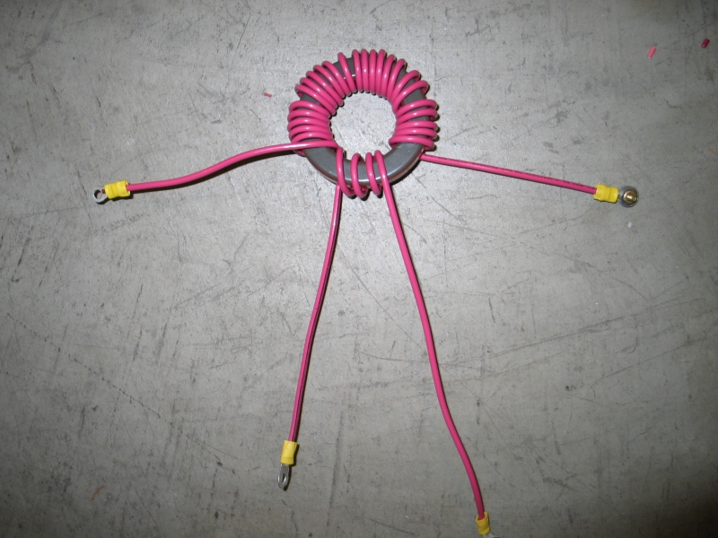
Here are some photos. First, the powdered-iron toroid; 4-turn primary, 25-turn secondary:
Next, the DMM, showing that I really do have just under 14 V on the capacitor, and the scope settings:
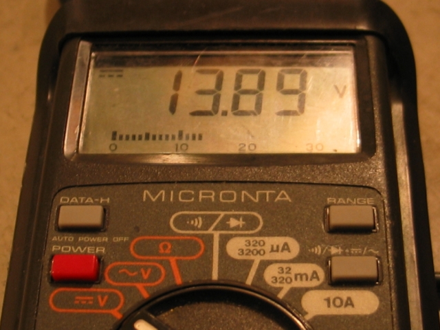
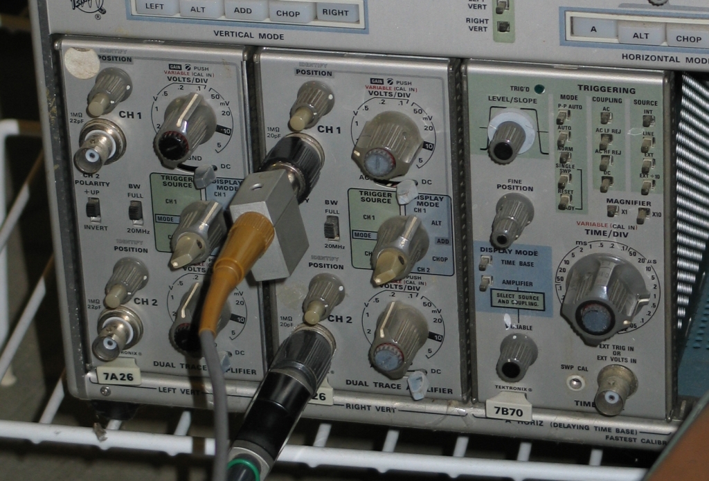
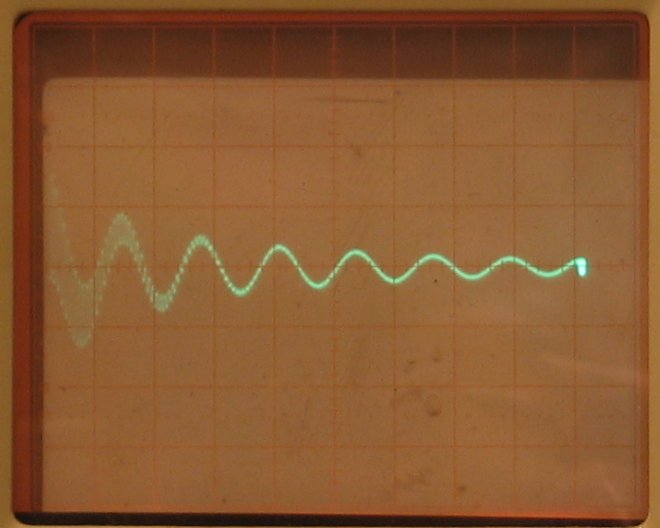
(We’re reading Channel 1 off the right vertical with a 10X probe, so it’s 10V/box; the horizontal is 1 μsec/box.)
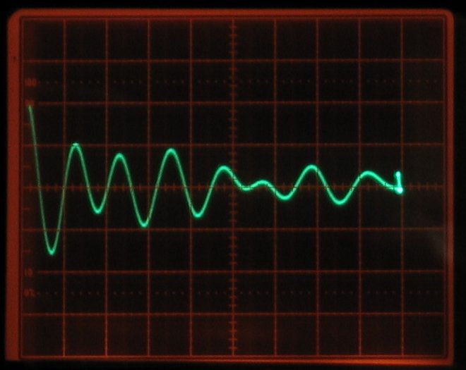
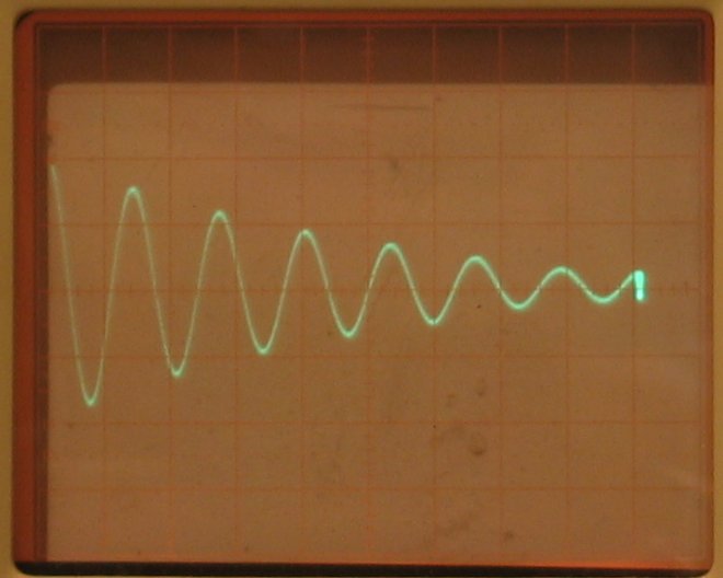
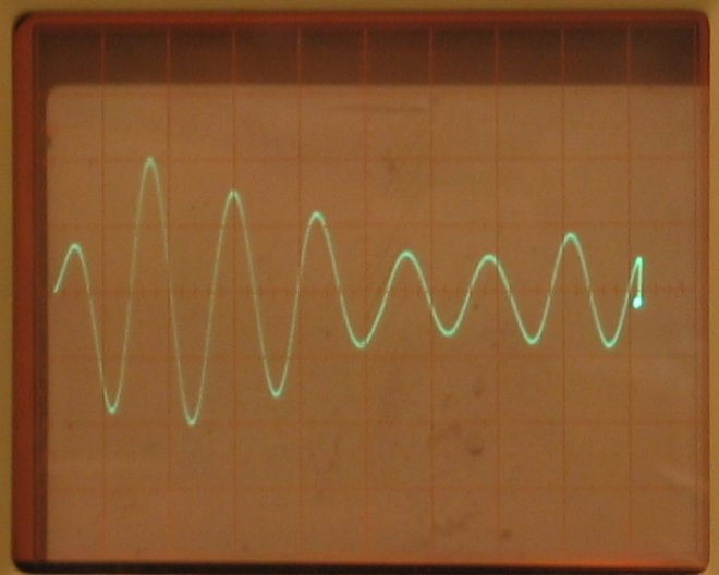
Here are actual traces; on the left is the powdered-iron toroid, and on the right is the air-core inductor. (The junk at the right end of each trace is evidence that the scope is having some problems, and should be serviced.)
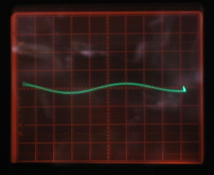
The risetime appears to be roughly 2 μsec for both. As you can see, though, there is something screwy going on with the toroid. I would expect to see almost as much voltage from it as from the air-core setup.
The obvious solution is to put a small capacitor across the air-core inductor to resonate it at the same frequency as the primary circuit, and thus turn it into a Tesla coil. That will get me much better voltage multiplication. (I will also take the primary down to 4 turns, to make things a bit faster, as the specification for the trigger pulse calls for 1 μsec risetime or less.) I’ll post more about this as I get going on it.
(06 January, 2006)
This is probably going to be viable, but I begin to observe something a bit strange. I’ll post photos when I get a chance to take some decent ones. What it looks like is that as I begin to add capacitance across the secondary I do, indeed, get to a point where the voltage is higher than in the photo above, ...but the maximum voltage appears to occur on the third half-cycle, not the first. As I say, I’ll post photos soon.
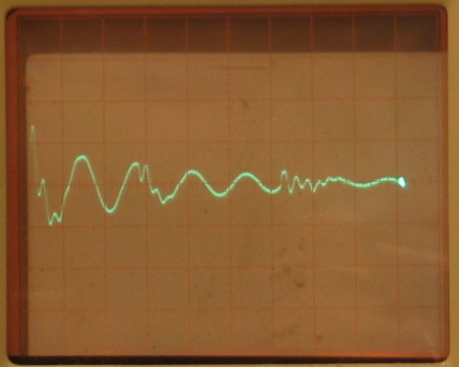
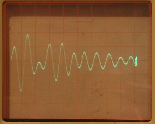
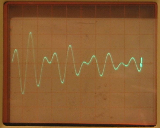
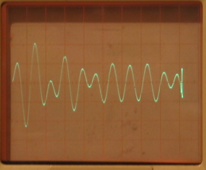
Here are two preliminary photos. The first shows the voltage across the primary during a test discharge, and the second shows the voltage across the secondary. For both of these there was ~32.7 nf of capacitance (which is too much) across the secondary winding.
The horizontal speed is 4 μsec per box, one fourth as fast as in the photos above.
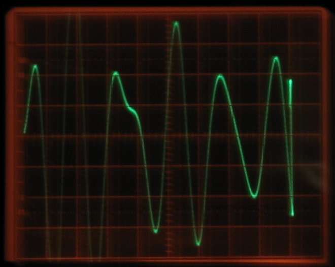
Unfortunately, I had the oscilloscope set to show the primary voltage as two vertical boxes for both of these. Future photos of the secondary waveform (which I will be able to take when the battery in my camera has been recharged) will have the primary voltage scaled to half a box. This will give me an absolute measure of the voltage multiplication I achieve.
(07 January, 2006)
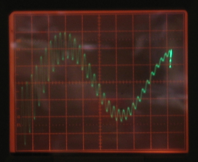
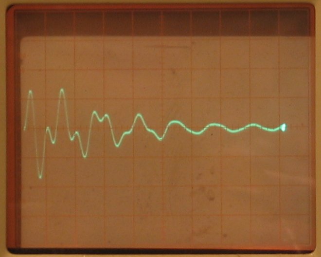
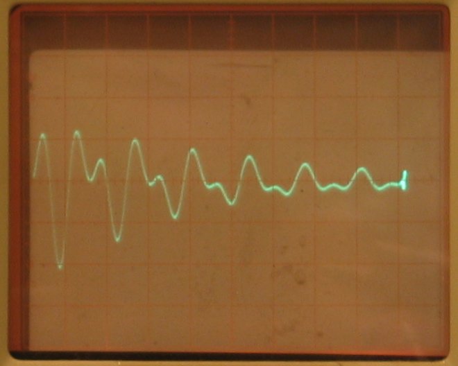
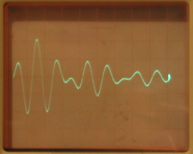
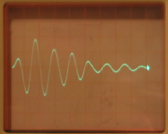
Oscilloscope photos. First, the primary waveform, full charge displayed as 2 boxes high, with no capacitors on the secondary. (Compare this with the photo on the left, above, in which there is about 32.7 nf across the secondary.) Second, on the right, the secondary waveform with no added capacitance. Clearly, there is a low-frequency component, an echo of the primary, and a high-frequency component that is the free resonance of the secondary.
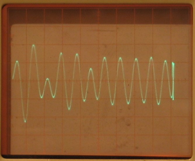
Next, photos of the secondary waveform, as I add capacitance to try to resonate it with the primary. First row: 1, 2, 3, and 4 capacitors; second row: 5, 6, 7, and 8 capacitors. The caps are doorknobs, nominally 2.7 nf each. (I don’t have a capacitance meter, so I can’t check the actual value, though I did discover that one of the caps I have is shot: the waveform didn’t change when I added it to the circuit. Closer inspection revealed an interesting crack in the epoxy...) The vertical scale here is 1/4 as sensitive as it is in the primary photo, so 2 boxes represents voltage multiplication of 4X.
My apologies for the fact that these images have some roomlight in them; the camera focuses much better if it can see something than it does if it has to use its built-in focusing light. Note that with 3, 4, 5, and 6 capacitors, we are getting more than 4X voltage multiplication. I would prefer at least 6X, because at only 4X I would have to put 3 kV on the primary to get the specified 12 kV trigger signal. Alas, judging from these, I’m not likely to get it.
Note, also, the fact that with 3 caps on the secondary, the maximum voltage occurs on the second half-cycle rather than the first one. By the time there 5 caps in place, the second and third half-cycles are about equal in amplitude; and with 6 caps in place, the largest peak is on the third half-cycle. So go figure.
Looks like my next step is to expand part of the region I’ve covered here, starting a bit below the 3-cap mark, and taking smaller steps until I get to someplace well past the 4-cap mark. Perhaps that will give me more of a hint about where resonance actually is.
Here are two photos, both with 3 large caps. The one on the left also has 3 small caps, the one on the right has only 2 small ones. (I suspect that I should try it with 4 small caps as well.)
This demonstrates some of the variability among capacitors: the basic waveform (before I added the small caps) looked much more like the “4-cap” waveform from the set above than it did like the “3-cap” waveform. That’s unfortunate, as I wanted to start near the 3-cap mark, and I will probably try this again soon.
In any case, it looks to me like I am getting just about 4.5X multiplication in both of these photos, and that’s a decent start. I may try a 3-turn primary and a 5-turn primary, to see how different they are from the current setup, in addition to tweaking the capacitors.
(8 January, 2006)
Scott Dorsey notes that PVC tends to be lossy at frequencies of a few MHz, and I worry about that, but even if I achieve 10-90 risetime of 1 μsec I’m really only at fractional MHz, so it shouldn’t be much of an issue. Still, something to think about.
(12 January, 2006)
Bob Chamberlin points out (as does Milan Karakas) that
the coupling between air-core coils is typically much
less than 100%. If I guess that I’m getting ~25%
coupling, then I should probably get 1/4 of the 16X
voltage multiplication that I would otherwise expect,
which matches the actual measured output quite
nicely. Either I am going to have to use very high input
voltage on the trigger transformer, which would allow me
to switch it with a spark gap, or I am going to have to
design and build a trigger transformer with much better
coupling, or I am going to have to use a commercial
trigger transformer. As it happens, I have a nice old
EG&G TR-136A (if I remember the model number
correctly), which is probably overkill for this service
but will certainly do the job.
My email address is a@b.com, where a is my first name (jon, only 3 letters, no “h”), and b is joss.
My phone number is +1 240 604 4495.
Last modified: Thu Jun 23 15:40:34 CDT 2016