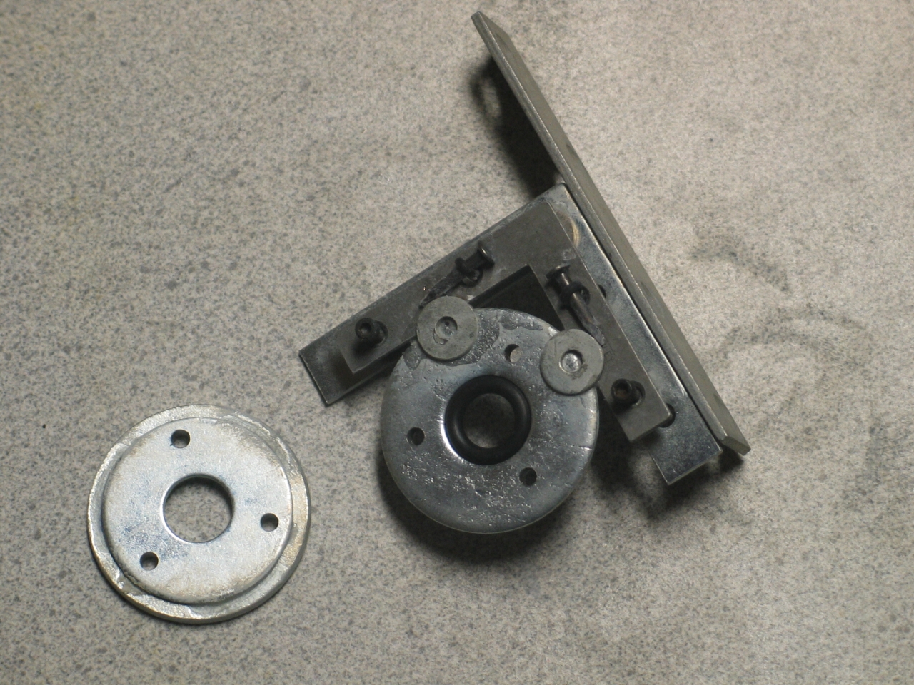
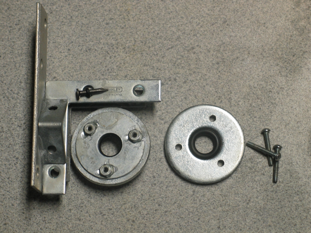
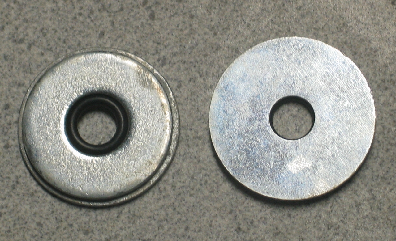
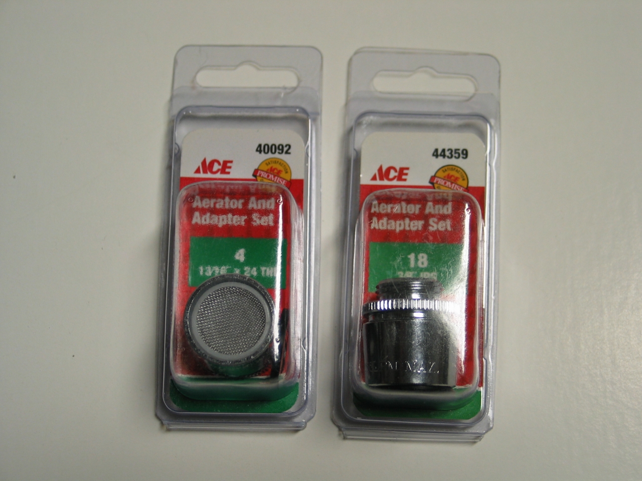
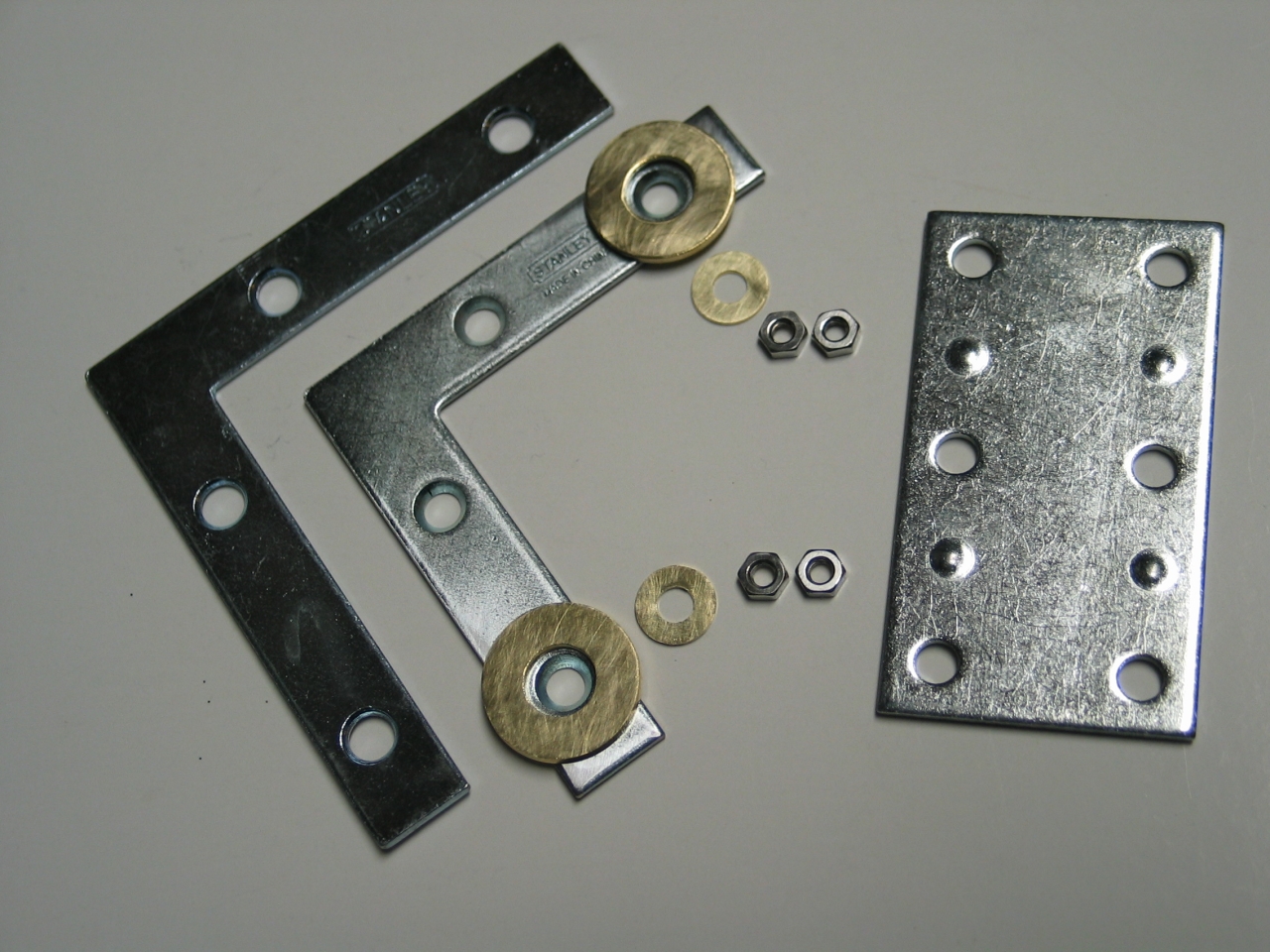
First, here’s a photo of the parts I bought when I started the project:
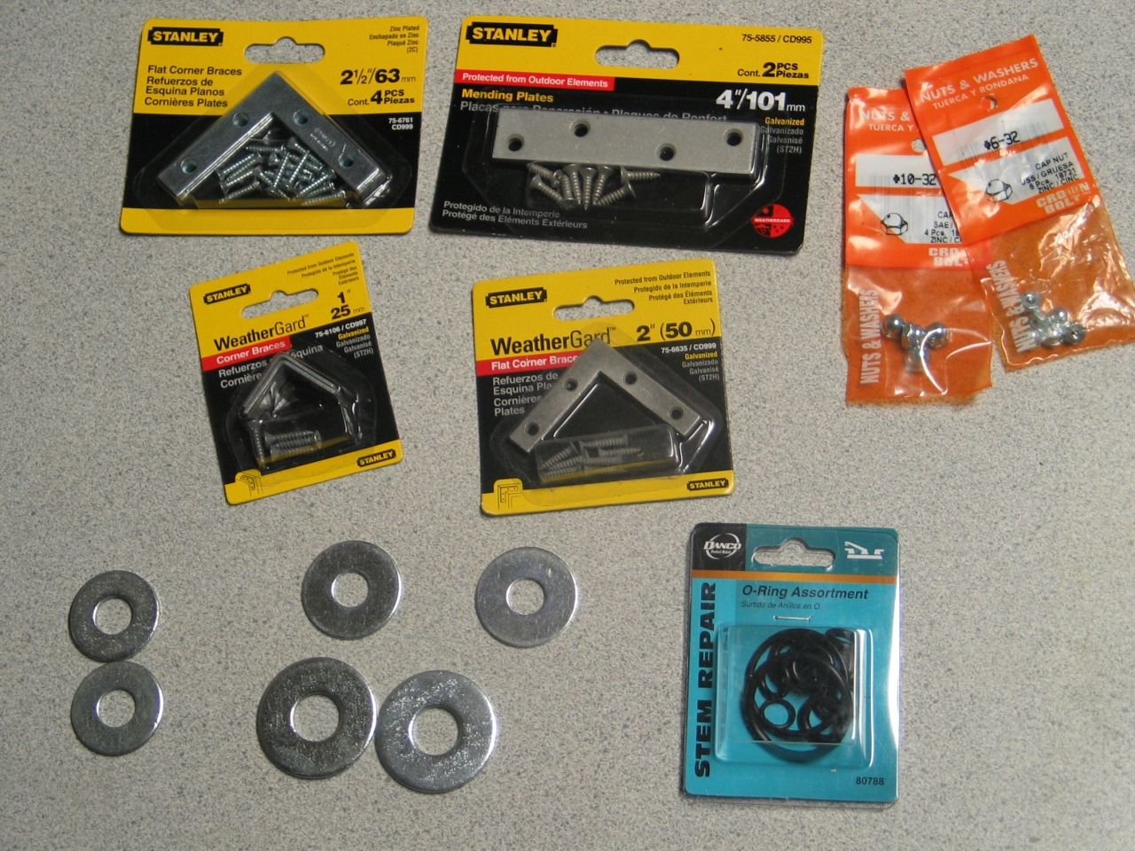
The total cost of what you see here was just under $17; but you also have to add the cost of glue and a few nuts and bolts that aren&squo;t shown here, so let’s call it $20. That’s unrealistically high, though, because there is more here than you need for one mount.
This mount is very easy to construct; it took us (I had help and advice from our loyal Range Safety Officer, LisaJulie Peoples) only 2 or 3 hours to assemble the prototype, even though we had to figure out what we were doing as we did it.
Please note that this first version is what I like to refer to as a “PoP machine”; that is, it is intended to provide Proof of Principle, and is not as robust as a final version. For example, this one is glued together with CA (Cyanoacrylate) glue; the real thing, further down the page, is glued with epoxy, which is much stronger and less brittle. It also doesn’t deposit white powder all over everything in its vicinity as it cures. (Ahem. Grump.)
Not Quite Step by Step:
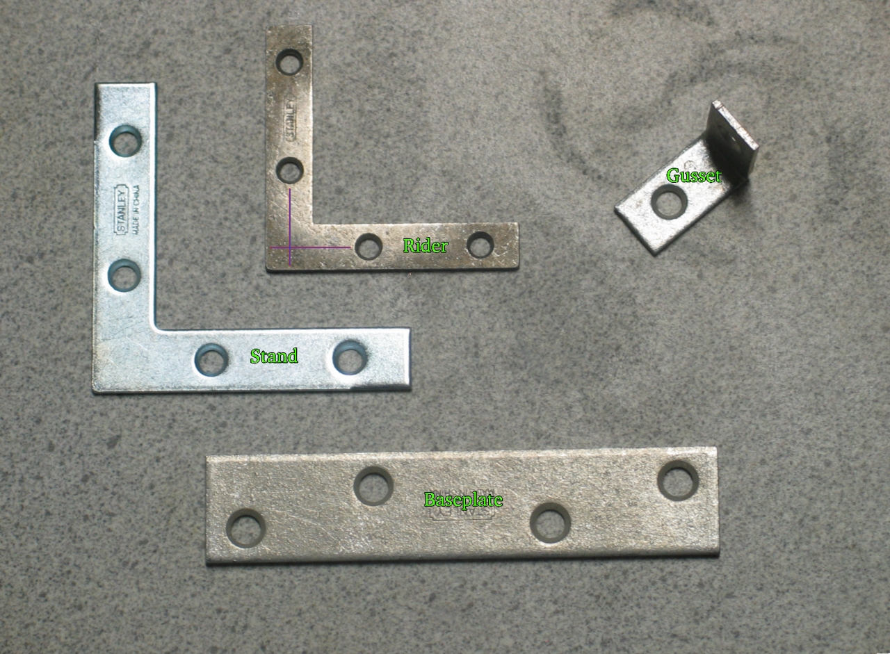
I was too excited while building the prototype to take photos of the early steps, but I have annotated the first one to make this a bit easier to follow.
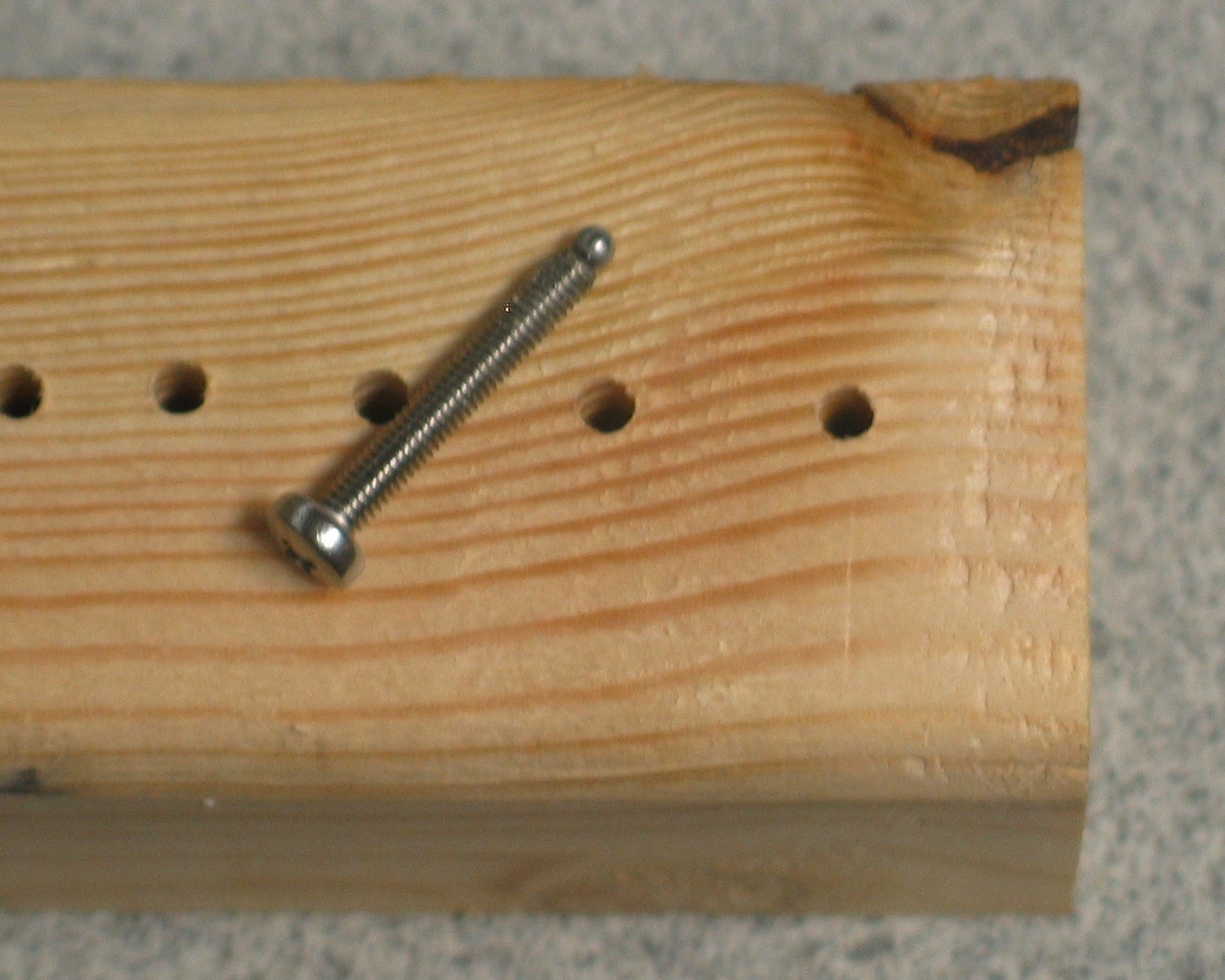
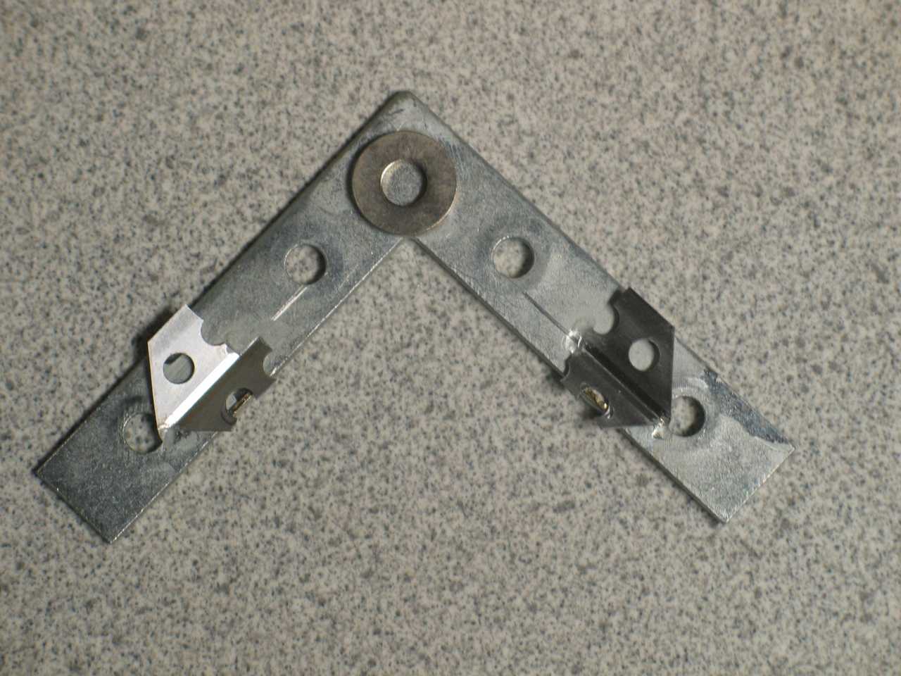
Draw or scribe lines on the back of the rider. They should be in line with the holes that define the X and Y rotation axes. (These lines are indicated in purple in the photo, immediately below.) The pivot goes where the lines cross; glue on either a steel ball (which can sit on a washer for added gluing strength and ease of positioning) or an acorn nut (which is easier to find, and will work adequately well). There is a detail photo, further down, showing the way I made the pivot on the prototype.
[I did not, btw, perform any machining on these pieces; all modifications were made by gluing things on. The one bit of machining shows up later, on the mirror holder.]
Glue nuts on the outermost holes of the rider. The adjustment screws will pass through these. (Later, we will add a secondary nut, to take out most of the backlash; for now, though, a single nut should do.) If you have trouble with the countersinking, just glue a washer on first. Then glue the nut over the hole in the middle of the washer. Remember to keep things as well centered as possible.
[NOTE: I describe a considerably more precise version of this mount later; you probably want to read through the entire description before you start acquiring parts or doing any construction.]
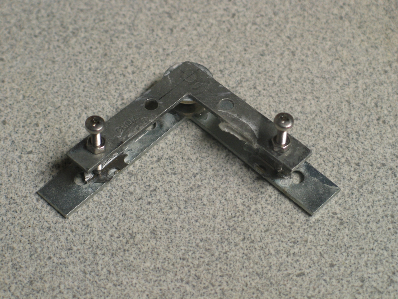
Position the rider on the stand, with a washer under the steel ball or acorn nut. (Your choice about exact positioning, but I will suggest that it is probably easiest and most effective to match the upper/inner edges.) Glue the washer into place, being careful not to get the acorn nut or steel ball stuck to it.
It’s a good idea to round the ends of the adjustment screws a bit, so that they move smoothly on the surface of the stand. You may also want to file or sand the surface smooth. For the proto, however, I didn’t bother. (Please note that we will get to a considerably better way to deal with this issue in a later version.)
I put smaller washers under the ends of the adjustment screws, to keep them from wandering about; but if you can arrange short narrow channels for them to “walk” along, that would be significantly less wobbly and more precise. (I actually did that in a later version of the mount, which is described further down the page.)
I glued the gusset and stand to the baseplate together; then I attached the rider to the stand.
You need at least one spring to hold the rider onto the stand, so that the adjustment screws will have something to push against. If you can attach a short strong spring in the inside corner, that will do. I didn’t have a spring of the right type, so instead I took a pair of o-rings from the assortment, and used one on each axis. They were just a bit long, so I put a twist into each one to tighten it. (Again, see the photos.)
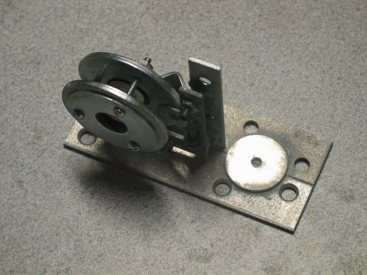
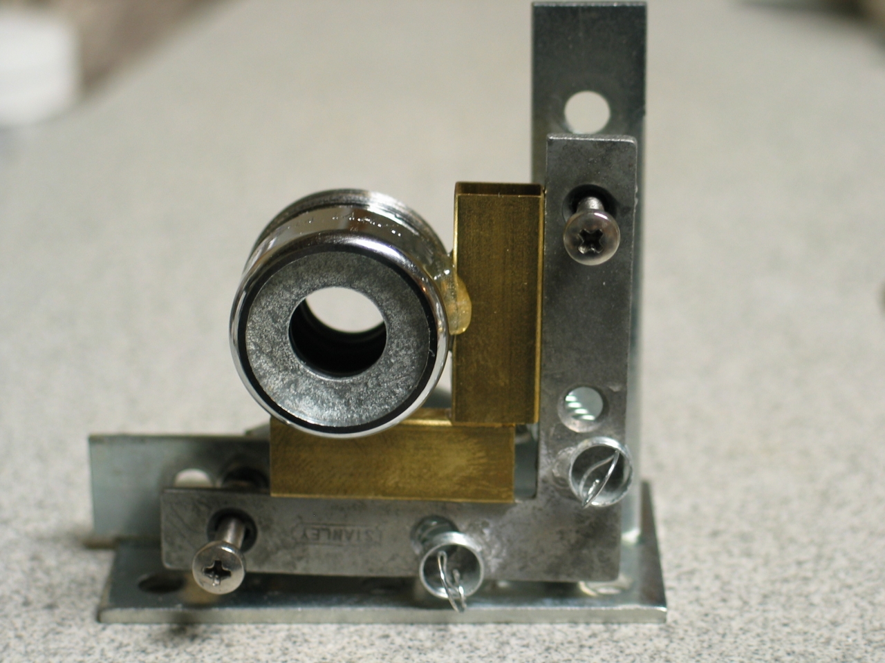
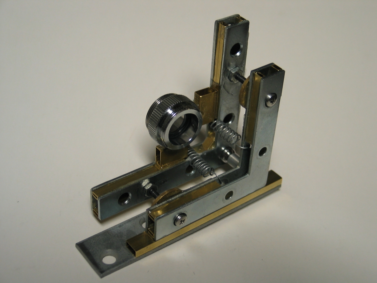
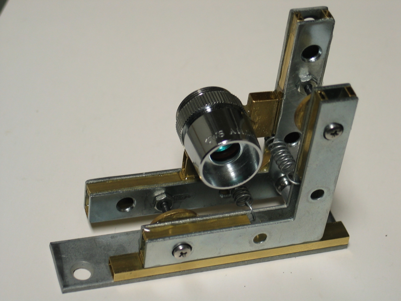
Here are some views of the completed frame, before I added the mirror holder:
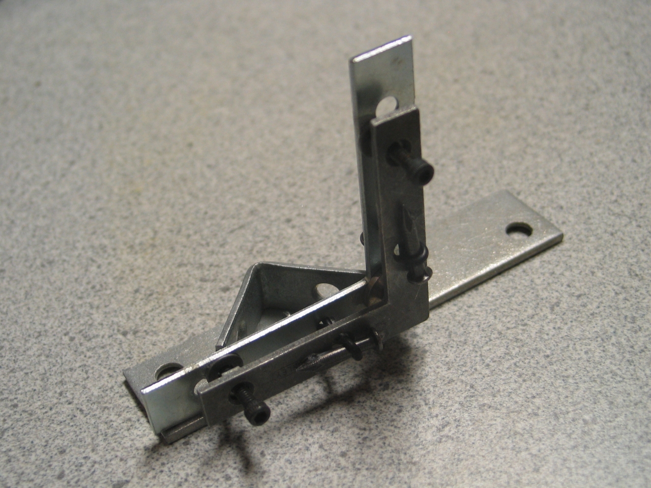
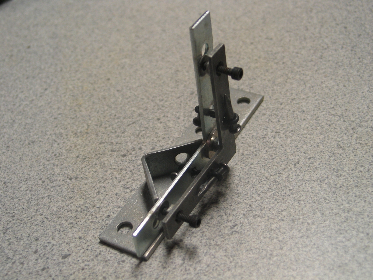
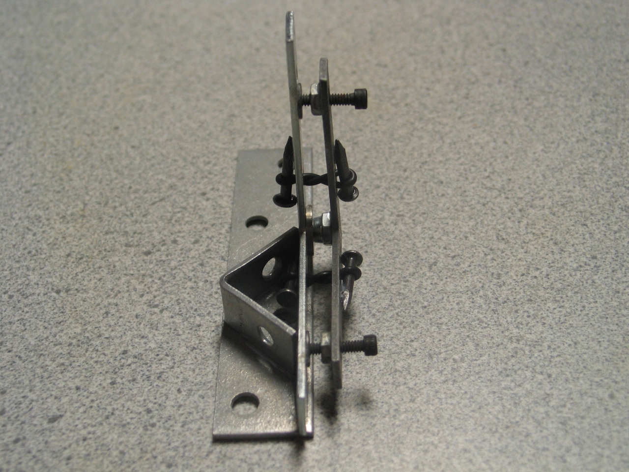
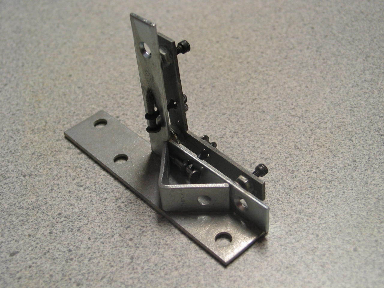
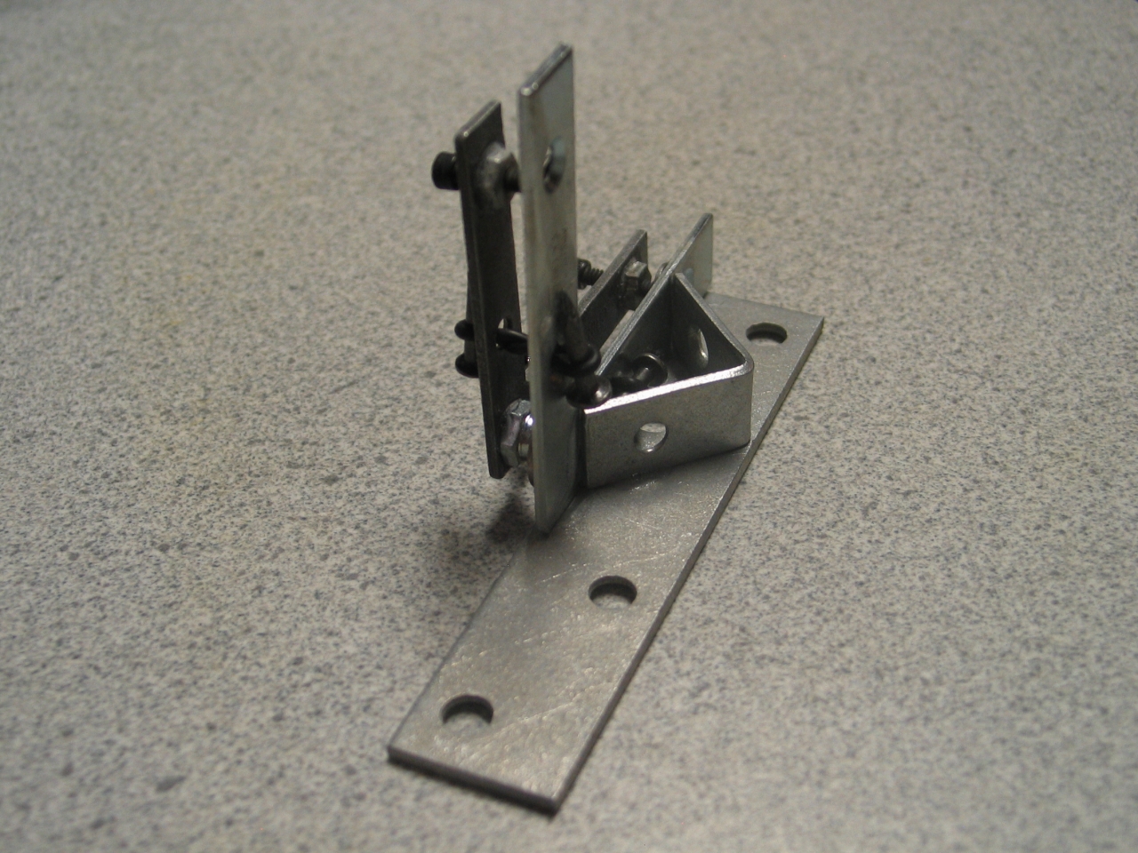
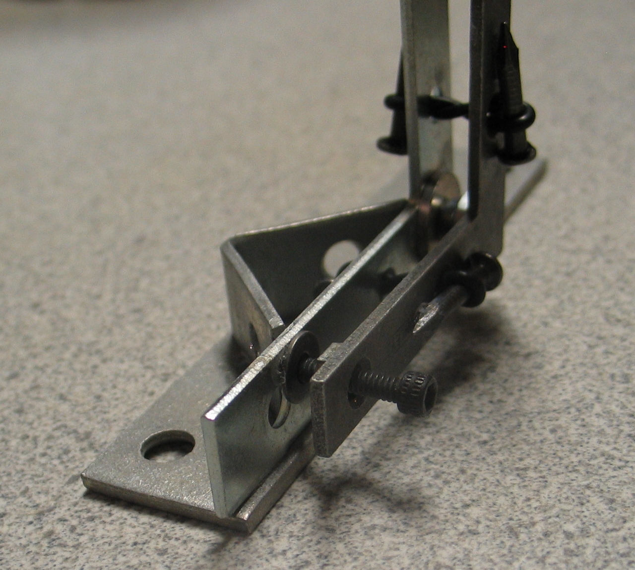
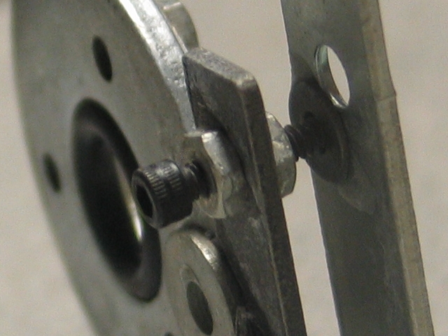
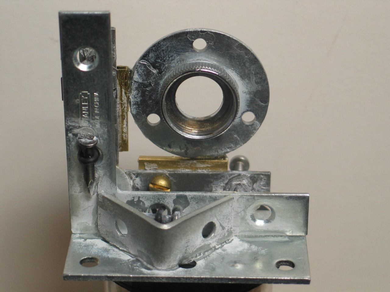
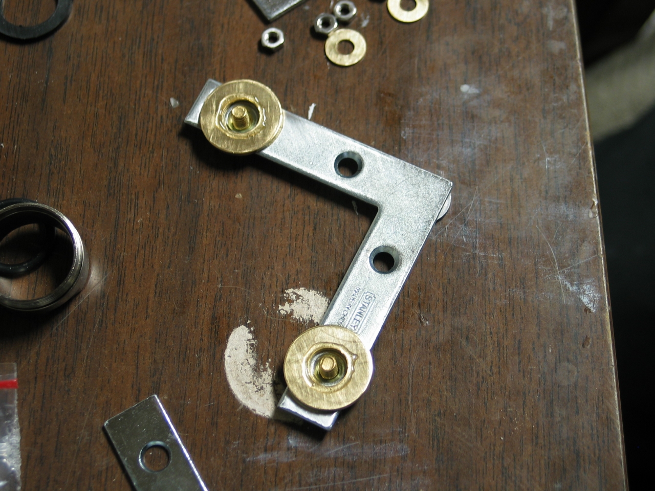
Here are two details, showing the washers I am using to keep the adjustment screws from wandering, and the pivot point:
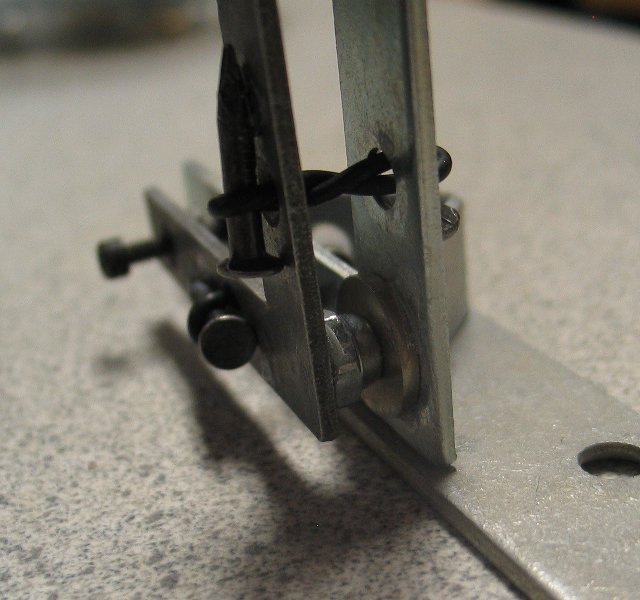
A steel ball, if you can find one of a reasonable size, is a better pivot than an acorn nut. I found steel balls at my favorite local hardware store (an Ace Hardware called Zimmerman’s), but I built the prototype with an acorn nut because those are much more commonly available. We will get to steel balls when we do the improved versions of the mount, further down the page.
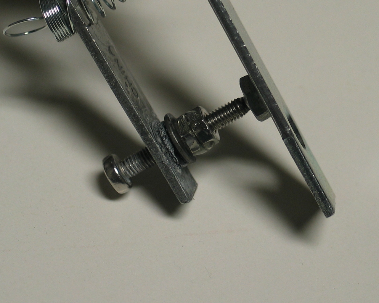
Here is a detail showing the second nut on one of the adjustment screws. I tightened this nut only until it became very slightly difficult to rotate the screw; then I glued it into place. This essentially eliminates backlash and wobble, and makes the mount considerably more precise. It also reduces the travel range slightly, but if I can find a longer screw at some point I can substitute it for the one that is currently in place.
[Note, added on 15 September, 2007: if you use sufficiently strong springs, and if the round ends of the adjustment screws are held in place, as they are in the third version of the mount, you probably don’t need anti-backlash nuts. They are, however, easy enough to make, and they do stabilize things, so I would suggest using them anyway.]
I made the mirror cell from large washers and o-rings. You can see most of the details from the photos. The one bit of machining I did was to drill holes in the mirror cell pieces for the bolts that hold it together. I used a drillpress for this, but you could do it with an ordinary drill if your hand is reasonably steady. (If you want to get fancy, you could drill both ends with the tap-drill size, then redrill one end with the body drill, and tap the other end. I just glued nuts onto one end.)
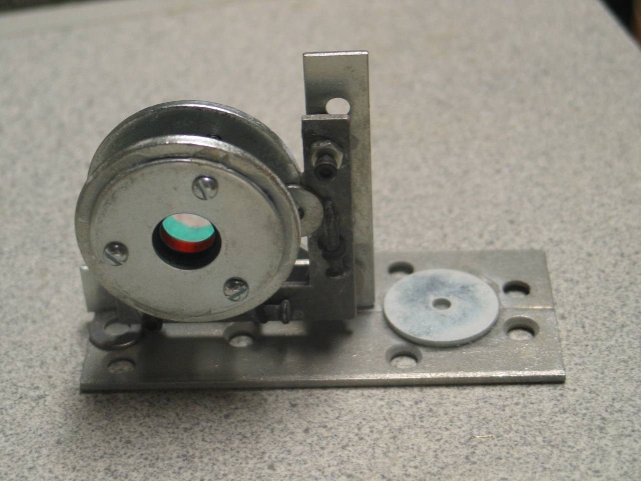
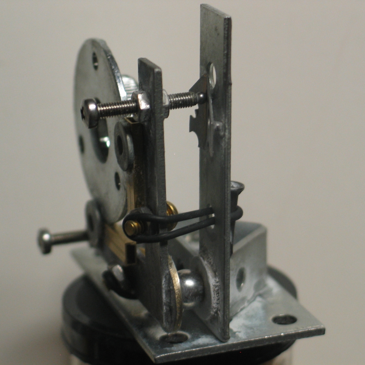
Here is what the mount looks like with the mirror holder in place:
The two washers that are visible in the photo on the left are basically gussets; the joints between the mirror holder and the frame consist of tiny dots of CA, and just aren’t strong enough, so I have reinforced them. (I would probably reinforce them even if they were epoxy, but you should probably take a look at the later versions of the mount for a slightly different and somewhat easier approach to this entire issue.)
Because I wanted to have a broad surface for the washers, I installed the mirror cell with the mirror hanging out the front. This is perhaps not the best orientation; left to its own devices, the mount falls on its face. While it is true that you will ordinarily be holding it firmly in place on an optical table of some sort, it is still a good idea to have it be stable on its own; you can use a wider baseplate, or use narrow gussets and orient the cell with the mirror behind the rider, rather than in front of it. (In fact, I reworked the prototype this way; see photos, below.)
This mirror holder is intended for 15mm optics. I also built one for 12.5mm or ½" optics, but did not put it on:
I am thinking about ways to make it easy to swap cells or to build a cell that holds multiple sizes of mirror, and if I get somewhere with either of those I will add a description.
Here are two photos of the mount on the bench, with a mirror installed in it. As you can see, I have broadened the baseplate so the mount doesn’t tip over.
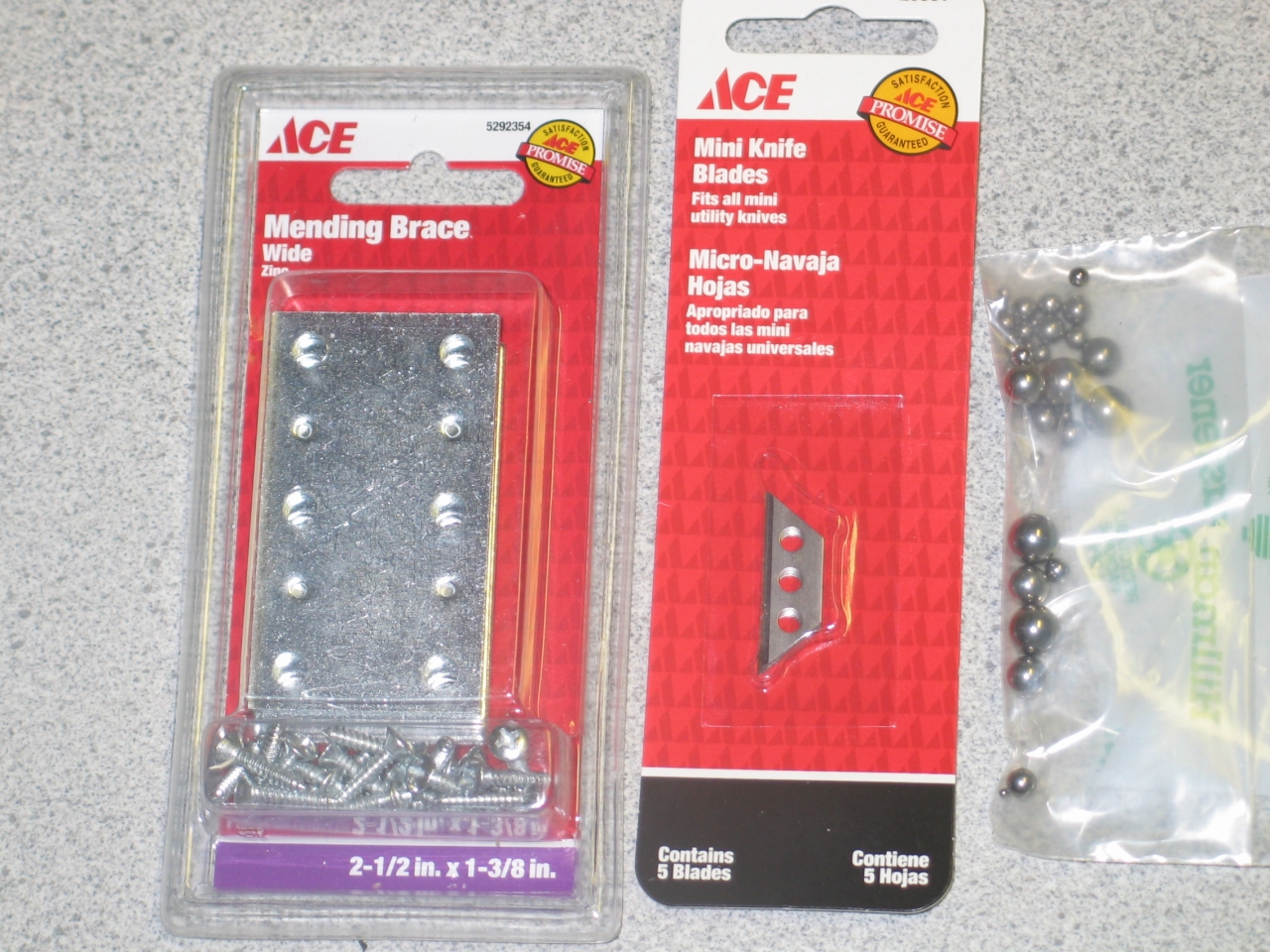
After I did that I found some very nice mending plates at Zimmerman’s, and I may just swap out the base. Here are the mending plates, the single-edge blades I hope to use as replacements for the washers that the adjustment screws ride in (I was lucky enough to find very small ones, but if you can’t find little ones like these, you could probably use injector razor blades), and steel balls in several sizes:
Version 2:
Let’s Try For a Bit More Precision
Having noticed that the ends of the adjustment screws were wobbling around in the washers that I used in the prototype, I decided that I wanted to have them ride in short channels, which would constrain them along the axes. (This is common in commercial mounts.) In order for this to work, the screws must terminate in smooth rounded ends. Rather than try to round them off, which is difficult even with access to machine tools, I decided to attach small steel balls to them. That’s not entirely trivial, so I thought for a while about how to accomplish it.
My first decent idea was to take a drill that is just big enough to make a body hole for the bolt, drill into something firm, drop the ball (which, obviously, can’t be any larger than the drill size) down the hole so that it lodges in the conical end shape left by the drill (which automatically centers it), put a dab of glue on the end of the bolt, and push the bolt in until it touches the ball. When the glue has set, you can remove the bolt.
This method requires a hole that is just barely big enough. The M3 bolts I acquired (initially intending to use them in the translation stage that I describe below), are about 2.91 mm in diameter; The closest drills I had on hand were ~2.75 and ~3.13. (I measured them with cheap electronic calipers, so don’t trust the last digit.) I thought about that for a while, and decided that if I used a slightly small drill, and drilled the hole in fairly soft material, I could probably just screw the bolt into the hole until it reached the ball. This should provide better centering than a hole that is wide enough for the bolt to wiggle inside it.
The first material I tried was end-grain balsa wood. That’s probably a little bit too soft, so I went for end-grain basswood on my second attempt. I am now beginning to think that it is probably necessary to clean up the end of the bolt a bit before attempting to glue the ball to it, and I am not sure that even basswood is hard enough.
(27 August, 2007)
Yesterday I drilled into a harder piece of wood, and found that it seemed to work slightly better. I also measured a 4-40 screw; it was about 2.80 mm diameter, so the drill that measured 2.75 mm is probably a nice fit for it. Today, however, I went to Zimmerman’s and discovered that a #32 drill is just the right size for an M3/0.50 bolt: my calipers give it as 2.93 mm, and if I drill into pine (I used a scrap that had been cut from a 2x4) the screws just slip into the holes with a little effort. This ends up working extremely well, though occasionally one of the balls ends up being somewhat off-center, so you need to check them before you use them.
Here’s a photo of an M3 with a ball on it, sitting on the piece of scrap that I drilled the holes in:
I then went back to Zimmerman’s and found special wire-gauge drills. The #34 drill turns out to be just about right for a #4-40 screw, and I had no trouble putting small steel balls on the ends of the adjusting screws for the mount. (More about this, however, later.)
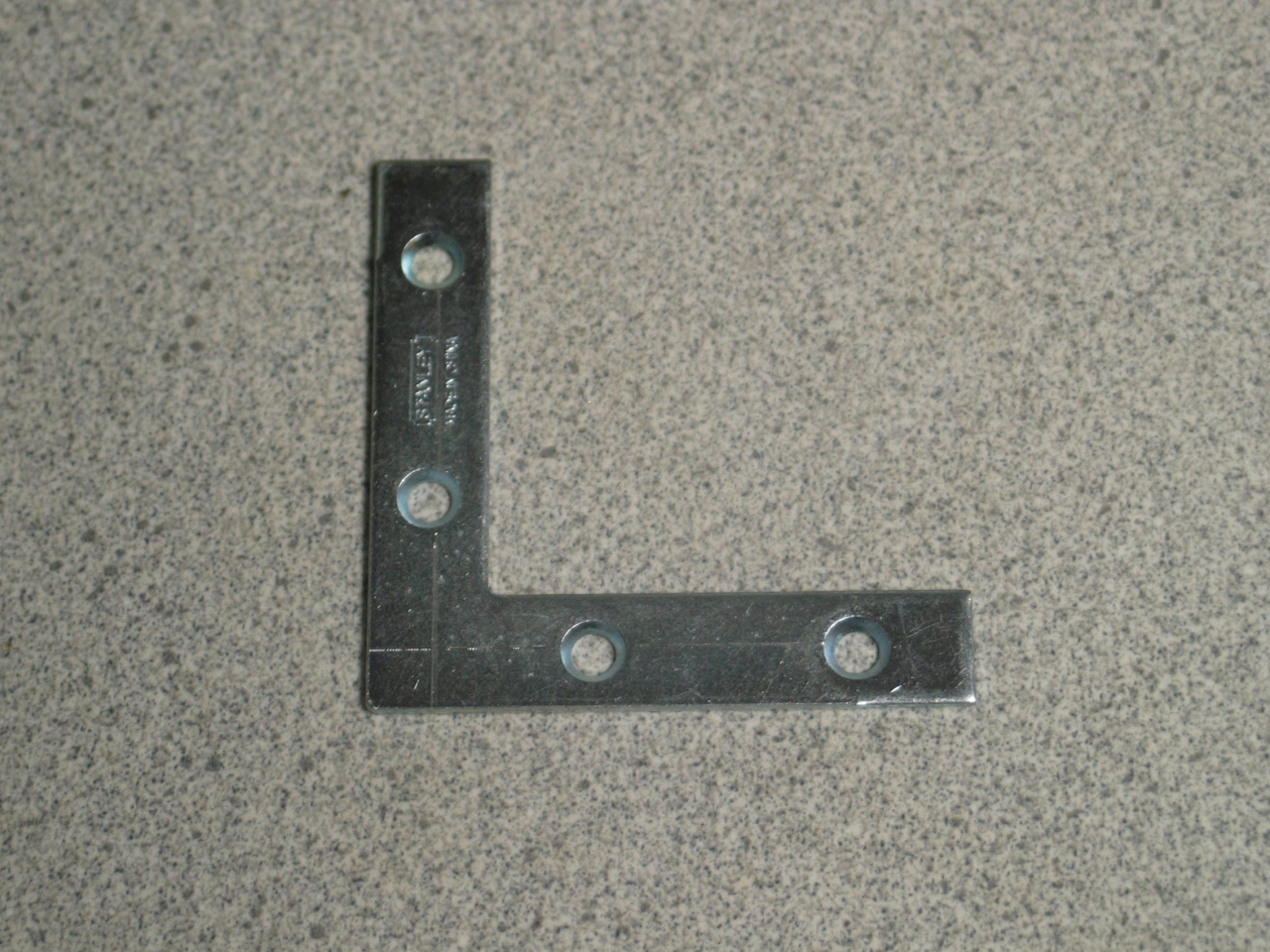
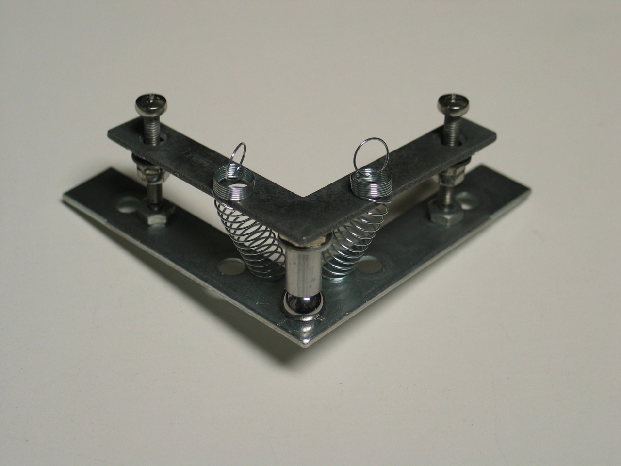
As long as we’re going for precision, I removed the acorn nut from the stand and put a washer in its place. This time, we will use a steel ball. I also scribed lines on the stand, to indicate positions for the V-channels that the little balls on the ends of the adjustment screws will ride in, and also for the washer that the pivot ball rides in. Here is a photo of another L, showing this:
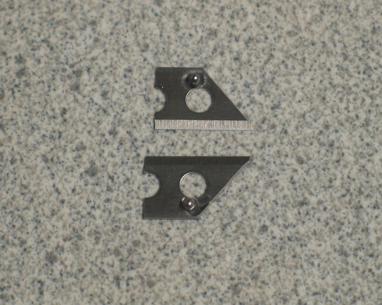
To make the V-channels, I started with one of the tiny razorblades I show above. I snapped it in half, because the travel distance involved is so tiny that I don’t need anything like the full length. (Safety note! Use Vise-Grips® or other locking pliers, wear safety glasses or goggles, and snap away from yourself! Also, be careful of your fingers around sharp edges.) The blades are quite brittle, so it should be relatively easy to snap them. If you are having trouble, re-examine your setup.
The blades need to be tilted to create channels, so I glued a 1/16" ball under each of the pieces, and used CA to glue them down to the stand. (Remember to wipe the oil off them before you try any gluing. Again, be careful.) Here they are, before I glued them down:
As you can see from the next photo, there wasn’t enough room for a steel ball under the opposite side of the channel, so instead I used short pieces of wire-wrap post, which I happened to have lying around. This makes the channels asymmetric, but I doubt that it will be an issue.
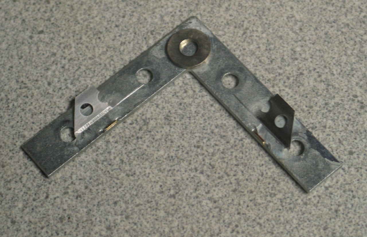
I found that I had to snap the back edges off the blades, because otherwise they were unbalanced and fell off when I tried to position them. In fact, gluing the bits for this was very delicate work, and I had to reposition things once or twice.
As long as I had things apart, I flipped the traveller over so that the mirror cell would be over the [new] base, and the mount would not try to tip over. I also substituted M3/0.50 screws, which have finer thread pitch, for the #4-40s I was using. The 3/32" balls work very well with M3 screws, but if you go with #4-40 screws you will also want to go with 1/16" steel balls, which will fit through #4-40 nuts. That, or be sure to put the nuts on before you do your gluing. Ahem. (Yes, my mileage varied. The 4-40 socket-head capscrews look very nice with the 3/32" balls on them, but when I tried to put them back onto the mount, they, uhhh... hmmm. Yes. Well. M3 it is, then. We will, however, return to this issue later, and make good use of it.)
The positioning of the pivot appears to be even more tweaky and crucial than I had thought, and I’m not sure I have it right even now. It turns out that the channels fix the position of the ball, and if the washers for the pivot are not precisely where they need to be, one of the adjustment screws (or both) won’t sit in the center of the channel, or will walk out of the channel as you adjust the mount. This also happens if the channels are not aligned well, which is basically saying the same thing. I may have to figure out a more advanced way to build this version. (Makes me want a rather precise 3-axis positioner, but that’s a large project in and of itself.)
I am lightening the mirror cell, which is just too heavy for this somewhat more delicate design. I have ditched both of the larger/thicker washers, and I’ve been looking around for other ways to hold the o-rings in position. One thing that suggests itself is part of a faucet aerator, which you can see in the photos below. Another is the neoprene washer from a garden hose. Both are very slightly large, but I think they’ll do.
Here are two views of the nearly-completed mount. (The back half of the mirror cell is not attached.)
It occurs to me (time for a small epiphany, I guess) that the only way to prevent at least one of the adjustment screws from walking out of its track as the other screw is moved through a wide range is to put the pivot point (which in this design is at the center of the pivot ball) in the same plane as the V-channels. (You can accomplish this by drilling a hole, just almost large enough for the ball to go through, in the stand. Glue the ball in place. Let it ride in a washer that, if necessary, is held a short distance away from the rider on a stalk.)
In the meanwhile this mount is quite usable over a range
of perhaps a degree or three in both axes, and I think
it’s a very decent start. On the other hand, it’s
annoyingly tweaky to build because everything has to be
lined up really carefully and accurately, so...
(29 August, 2007)
Version 2 of the mount is certainly viable in a general
sense, but I want something simpler that works at least
as well. It occurred to me that instead of trying to get
the ball-ends of the screws to run in channels, it might
be possible to maintain the position of the ball end,
and take up the slack elsewhere.
The issue here is that if I position the ball end of the
screw firmly, the angle that the screw makes with the
rider must change as the angle of the rider changes. If
the pivot point is not coplanar with the ball ends of
the screws, the angle changes in both axes. I originally
thought about bearings and/or slides, but the
aforementioned Range Safety Officer suggested neoprene,
in the form of o-rings, grommets, or faucet washers, for
the compliant couplings. At first the neoprene idea
seemed like it might be too loose, but after some
thought I decided to give it a try. I found, somewhat to
my surprise, that faucet washers are probably too stiff,
and I have switched to o-rings. O-rings appear to be
just about right for this, and the revised design is
noticeably simpler than the previous version. (There
will, however, be further changes, so please keep
reading.)
I am working up a diagram to illustrate the angle issue,
but it isn’t finished yet. When it is, I will
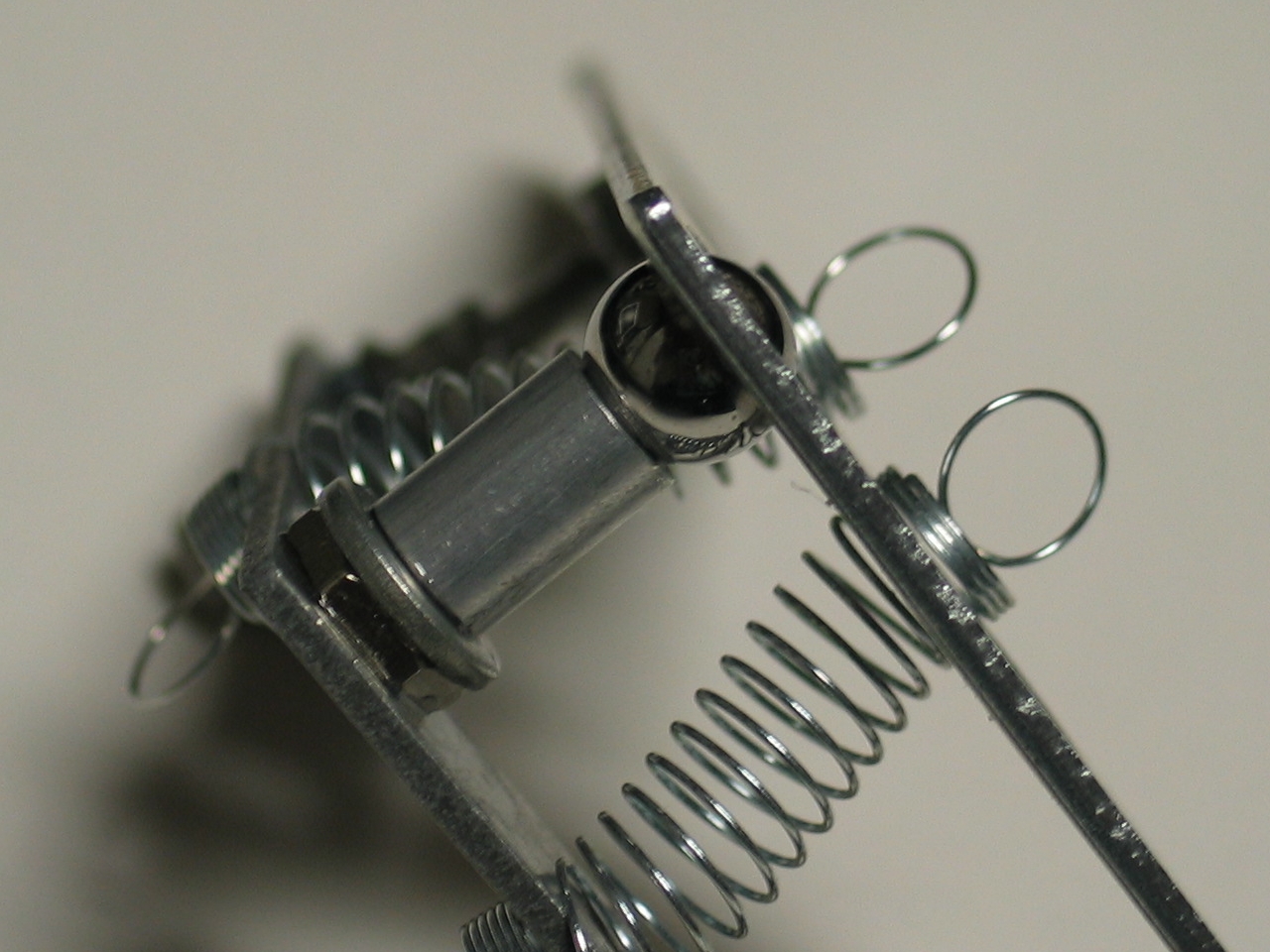
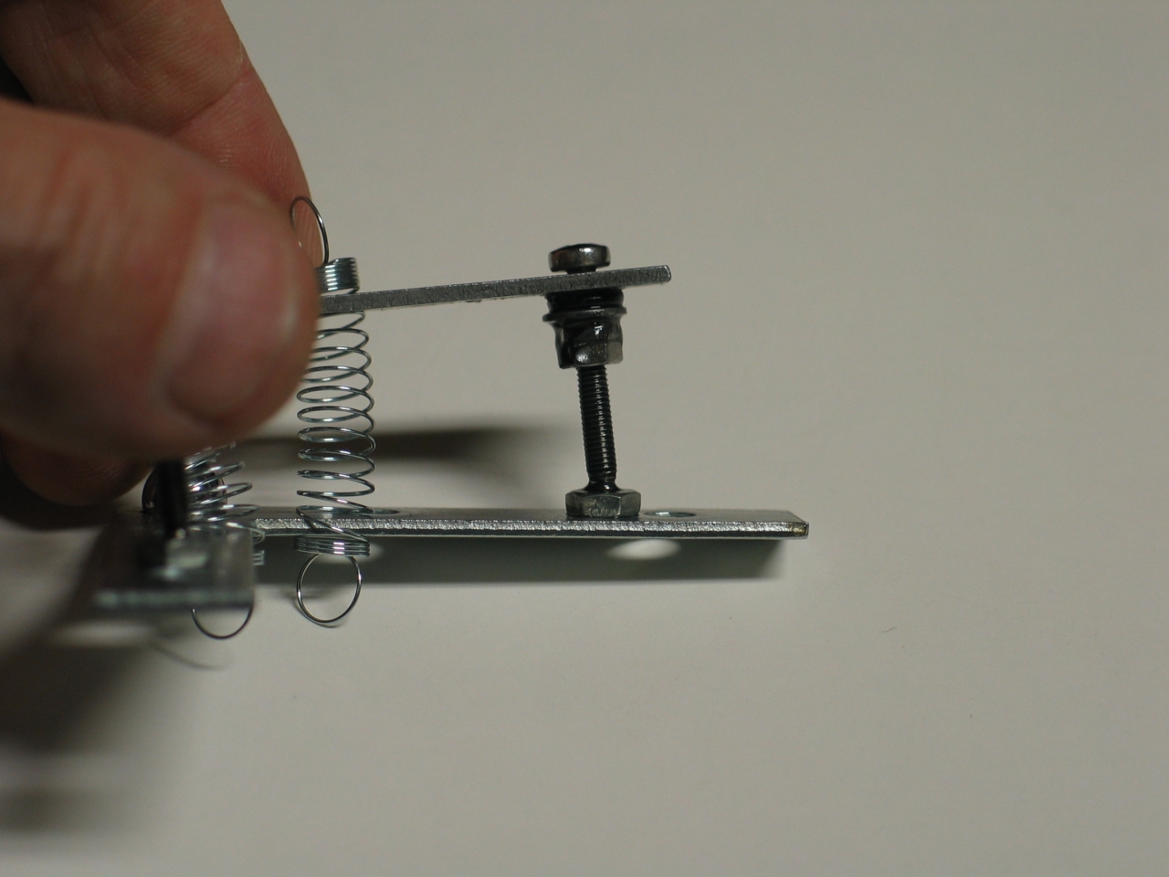
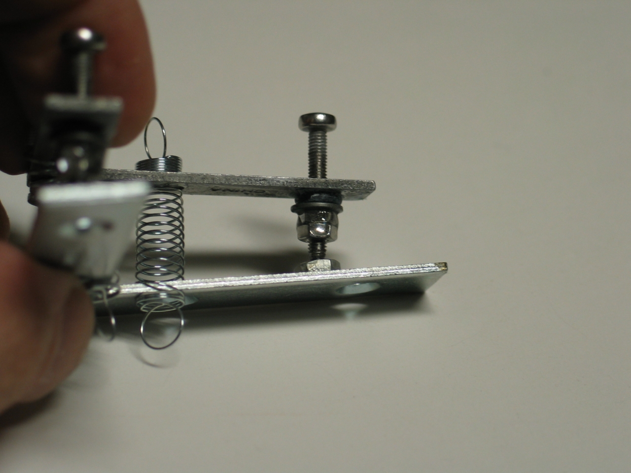
post it here. In the meanwhile, here are some photos of
the mount as it goes together. First, a detail of the
pivot point and a detail of one of the adjustment screws.
As you can see, I have drilled a hole in the stand. I
could have put the holders for the adjustment screw ends
on blocks as an alternative, but this was easier. (The
holders, btw, are just #4-40 nuts. Inasmuch as it was
clear that the little steel balls wouldn’t go
through them, they seemed like the obvious thing to use
here, and they work quite well.) If you build one of
these, it’s your choice. I will note, btw, that
the column you see on top of the pivot ball in these
photos is a little bit too long for the adjustment
screws I’m using now; I will be removing the nut
that is currently acting as a spacer. (In the photo on
the left, and in the inverted photo below, also on the
left, this nut appears at the base of the column.)
In the photo on the right you can see the o-ring, just
below and to the left of the anti-backlash nut assembly.
(There is a washer between it and the nut; I used CA to
attach the o-ring to the rider and the washer, and then
epoxy to attach the first nut to the washer and the
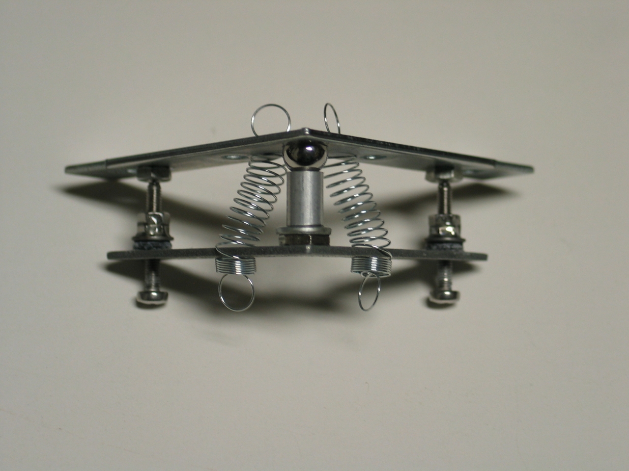
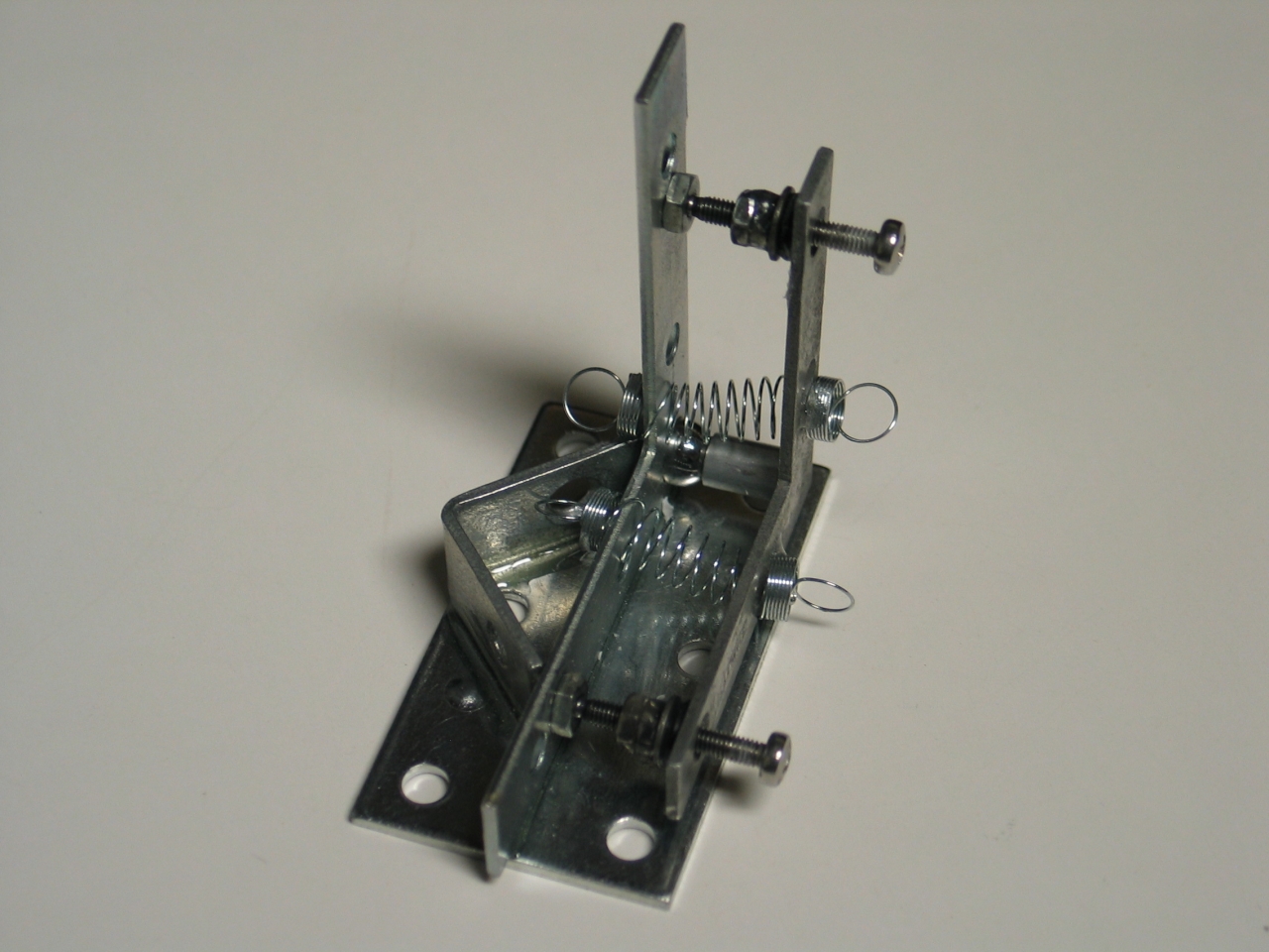
second nut to the first one.) Here are two overviews of
the mechanism:
Here is one of the screws just about fully extended, and
just about fully retracted:
The dark liquid on the screw in the photo on the left is
a wonderful lubricant called Dri-Slide®, which is
made by Lilly Industries. It contains molybdenum
disulfide, and will even work in vacuum after the
carrier evaporates, which takes a while.
Here is the basic mechanism on the base; I have removed
the hex nut (and the washer) from the column extending
“up” (in this photo, to the right) from the
pivot point to the rider:
I would not have bothered to remove those extensions
if my M3 adjustment screws had been 25 mm long; but
the longest I could find at the store was 20 mm.
It’s not quite over yet, though — I still
have to decide how I will make the mirror cell. I may
bite the bullet and design a cell that can be swapped
out, so I can change mirror sizes easily.
(30 August, 2007)
After considerable fussing in the plumbing department
at the hardware store, and then searching through my
odds and ends here, I have come up with what I think
is a viable mirror cell, at least for 15 mm mirrors.
(It may be possible to adapt it to 12.5 mm mirrors,
depending on the availability of appropriate washers
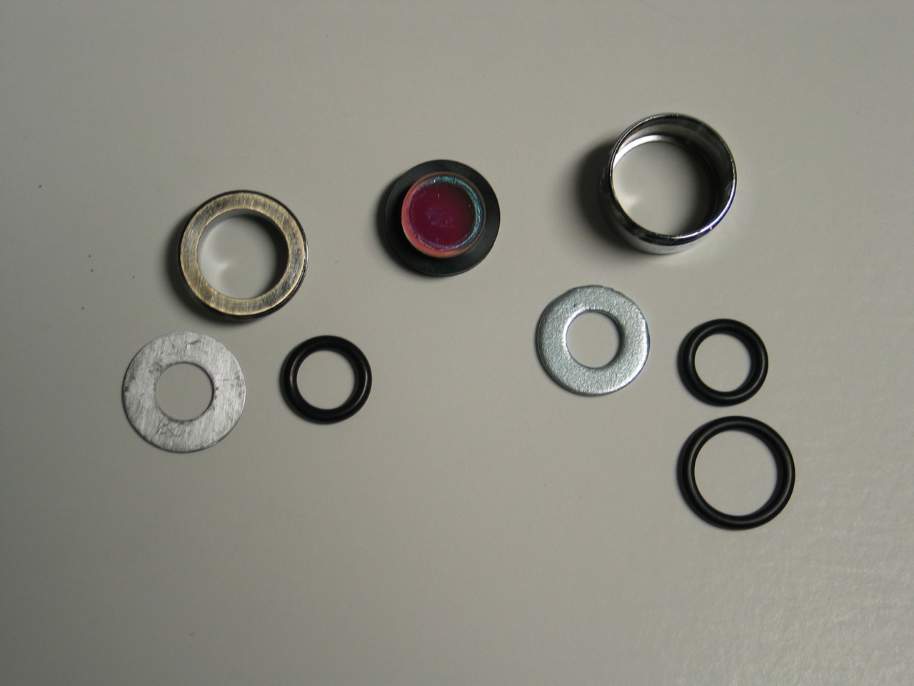
and o-rings.) Photos:
This is the body of a sink aerator, with a washer
dropped into the bottom as a stop; on top of the washer
are two o-rings (obviously, if I just put the smaller
one in by itself, it would not remain centered). The
mirror is centered by a neoprene washer, and is held
in by an adapter onto which I epoxied another washer
(again, as a stop), and into which I dropped another
o-ring. (Adapter, washer, and o-ring are on the left
in the first picture; mirror in the middle; aerator
body, washer, o-ring, and neoprene washer on the right.)
(Note, added on 31 August, 2007)
I went back to Zimmerman’s and found that they
sell aerators with the adapters already in them, which
makes this a whole lot simpler. Here are two types:
These do require a bit of care when you go to attach
them to the mount, as they are tapered, but it
isn’t particularly difficult.
(end of note)
The mount is now complete; let’s put the mirror in,
and see how well it works...
...The first thing I noticed, after I got it onto the
bench, was that the adjustment range is huge; it seems
to be about +/- 5° in each axis, though I
haven’t actually measured it yet. (I put a HeNe
with a white card on the front a little less than a foot
and a half away from the mount, so I could see the
return, and at the end of the adjustment range the
return was off on the wall someplace, a surprising
angular distance from the laser.)
Coarse adjustment was easy, but when it came to fine
tweaking I found myself wishing I had socket-head
cap screws. Such is life: I used what I could find.
(You can always go to
MSC Industrial Supply
if you decide you want stuff that is fancier than
whatever your local hardware store has in stock.)
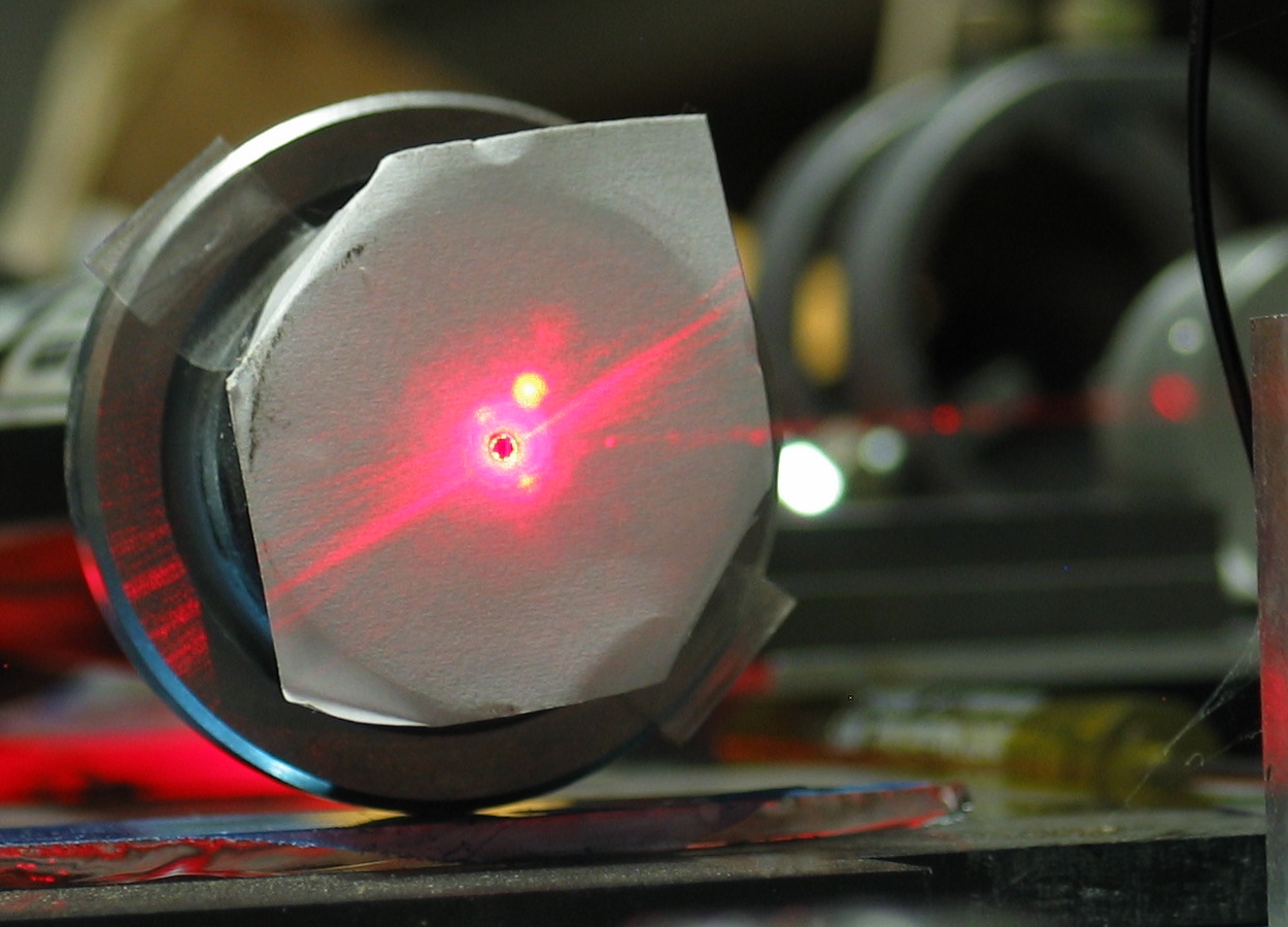
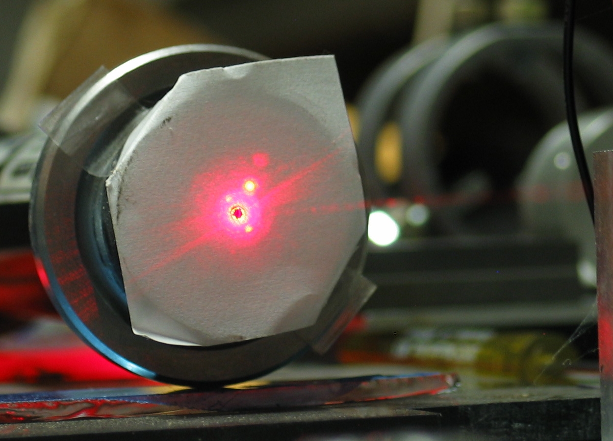
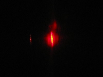
Here are two photos of the front of the laser, with
the return beam from the mirror going straight back
into it:
The laser did a lot of mode-hopping at first, even
though the mirror is quite blue and does not reflect
much in the red part of the spectrum. You can see some
of the appearance of mode-hopping in the photos above,
though of course it is a dynamic process, and I should
probably take a video of it. What really caught me by
surprise was something I was not able to capture
directly with the camera: the laser also changed color
for short periods (!).
If you were not already aware of this, HeNe can put out
several visible lines, including green (543.5nm), yellow
(594nm), and orange (612nm), in addition to the usual
red at 633 nm, a slightly longer red, and some lines in
the IR, of which I think 1523 nm is the most common. In
fact, the first gas laser was a HeNe, and it ran on one
of the strong IR lines, not the red we are now so
familiar with. (That came along a month or two later.)
In connection with this, btw, I seem to recall that 6 or
7 of the lines share a common upper state. Because the
cross-section for stimulated emission decreases as the
wavelength gets shorter, it is easiest to get lasing on
the longest line of the set, which happens to be an IR
line. In fact, if you have a very high-power HeNe, with
a long tube, you have to take steps to get much power in
the visible, as the IR line tends to operate even with
red mirrors, and it steals power from the red line.
The green line, being the shortest, is the most
difficult to lase, and 543.5 nm “GreNe”
[that may be a trademark] lasers generally don’t
put out much power — I think half a milliwatt is
fairly common. They also tend to be rather expensive.
After lots of fruitless attempts to show the color
change by pointing the camera at the laser, I put the
spectroscope (bottom of this page) behind the mirror,
and managed to get some evidence.
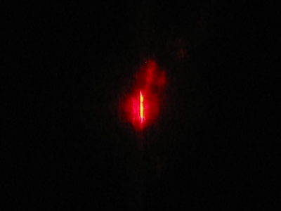
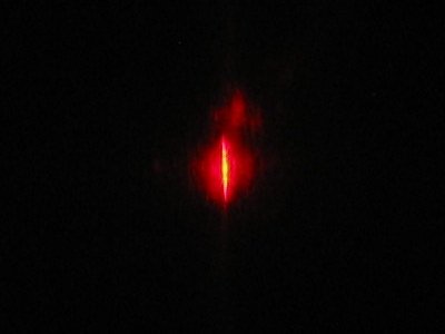
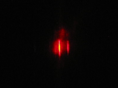
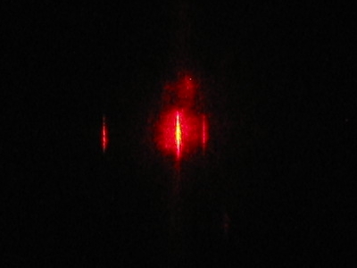
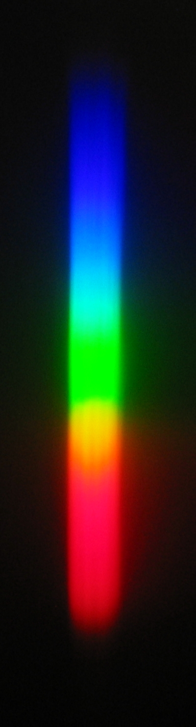
Here are 5 photos. The first shows just the regular HeNe
red at ~633 nm; if you look at the second carefully, you
may be able to make out just the ghost of a second line,
a little to the left of the main one. In the third image
there is a line to the right of the main one
(possibly 640.2 nm), and at least two ghosts to the
left. The fourth image clearly shows the orange line to
the left, and the line to the right; in the fifth, the
line to the right of 633 has gone away, but there is
still some orange coming out of the laser. (The camera
does not capture the colors well; the line that is well
separated from the main line on the left is distinctly
orange or yellow-orange to the eye, and the main beam,
which is overexposed here and looks bright yellow or
almost white, is the usual HeNe red color.)
(These are full-size crops from the original images,
so unfortunately I don’t have any that are larger.)
The laser did less and less mode-hopping as it warmed up
and stabilized, and there were fewer and fewer moments
when it changed color, though I found that I could
sometimes get a certain amount of color change for a
brief period by tweaking the mirror a little.
These photos are not really what this is about; but this
is the first time I’ve been entirely sure that I
was seeing a plain-vanilla red HeNe putting out other
colors, and I thought that was pretty interesting.
In any case, it is abundantly clear that although the
mount is a bit soft, in the sense that it bends a little
if you push with the screwdriver when you are adjusting
it, it is a pretty decent mount. It is reasonably easy
to adjust and set, and it holds a setting fairly well.
If you don’t need the very wide adjustment
range that this specific version provides, you could
easily just widen the holes in the L bracket a bit,
epoxy thin washers over them, and put the adjustment
screws through those. Remember to retract the screws
most of the way when you attach the receivers that the
balls ride in, to minimize the maximum angular
offset. That should give you a stiffer mount. In fact,
see below — I decided to try doing this.
Here is the beginning of what I am currently calling Rev
3A. It will have less range, but should be more precise,
as I am using larger brackets. It should also be slightly
stiffer; instead of o-rings, I am using the very slight
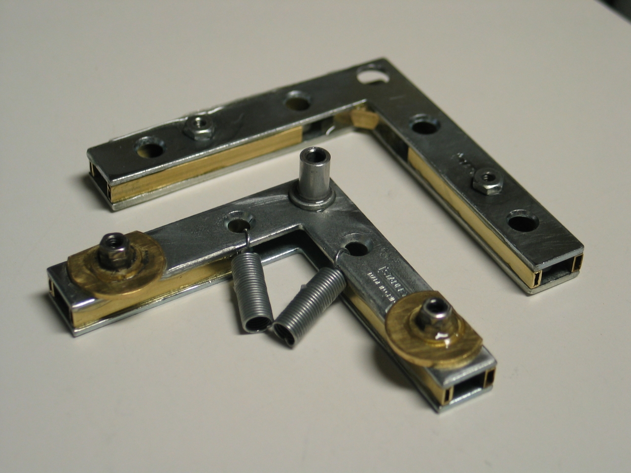
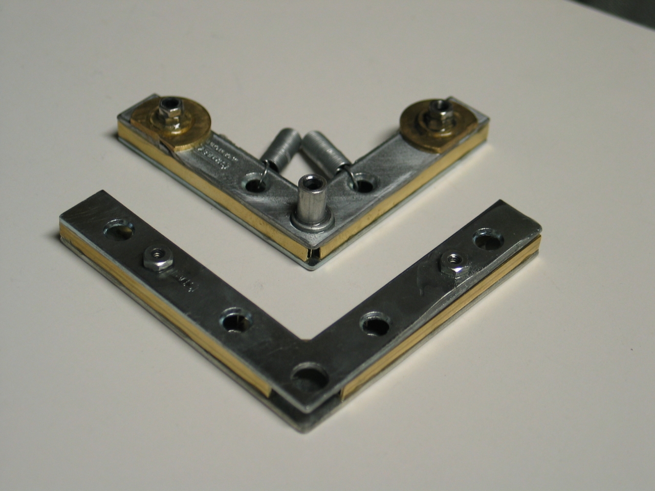
springiness of brass (bronze?) washers. Here are some of
the pieces:
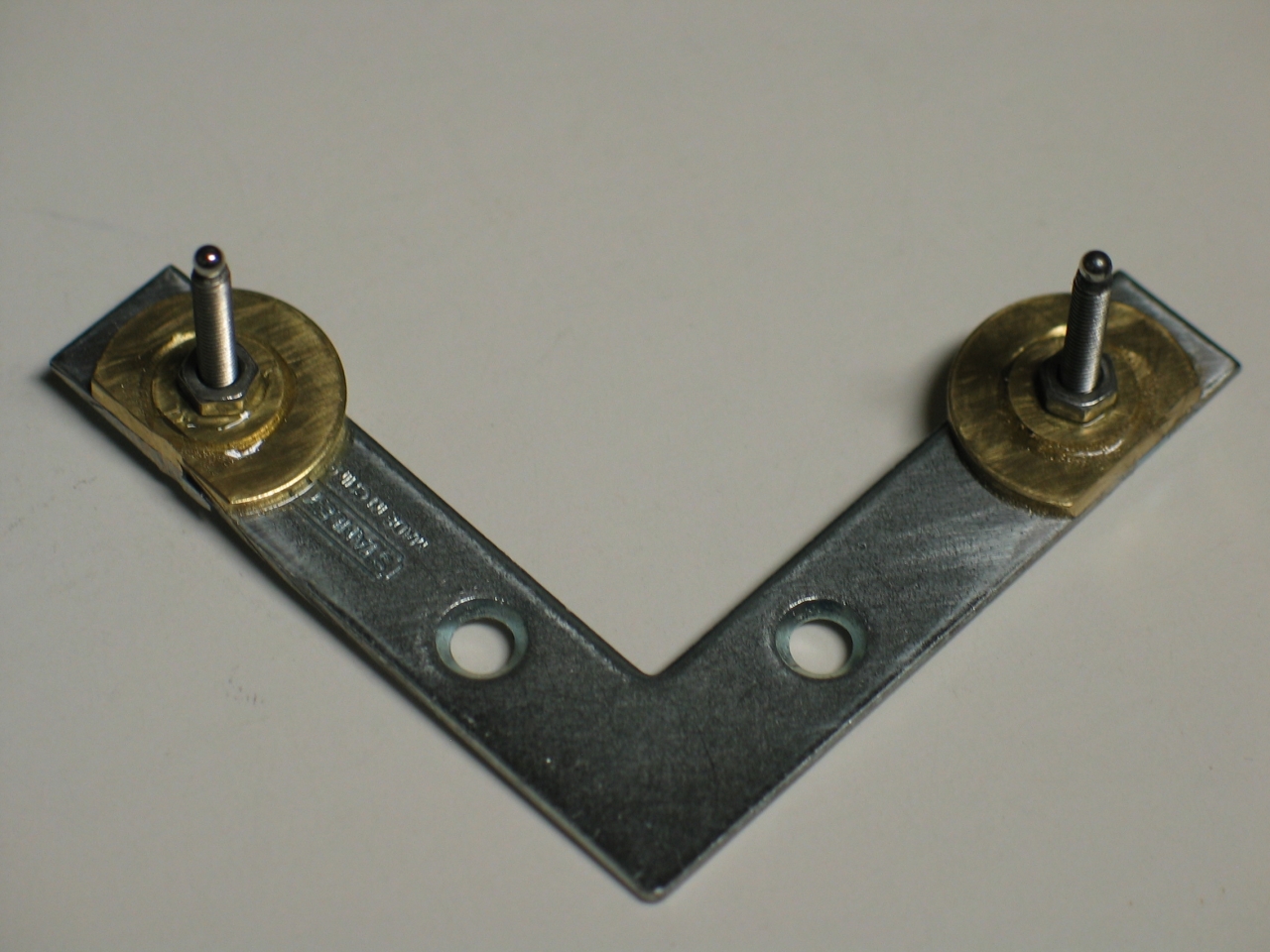
The first step is to attach the large washers to the
traveller; then the small washers go on top of those.
In the photo on the left, I have some machine screws as
positioning aids, and the epoxy is on the large washers,
waiting for the small ones to be placed. Once all of
that has set, the anti-backlash nuts go on the small
washers (which, btw, are #6), and the anti-backlash
nuts go on the small washers. In the second photo, I
have the first half of each anti-backlash nut in place.
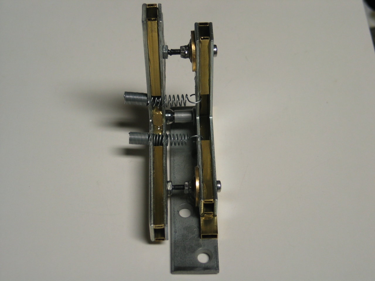
Notice the fact that I have (carefully!) sawed off
the lower edges of the washers, so that the bottom
of the horizontal-axis one won’t hit the base.
I haven’t decided which one will end up being
horizontal, so I sawed them both.
(03 September, 2007)
The above version of the mount, when I tested it, worked
fairly well; but I did notice that it was still a bit
more rubbery than I would have liked. When I tried to
adjust it, the pressure of the screwdriver made a
noticeable difference in the setting, which made it hard
to get precise control. I did succeed, but it was by
guessing where the aiming point would be when I let go.
That just isn’t good enough to satisfy, so I
thought it out, and concluded that at this scale even
steel is fairly soft if it’s thin enough. For
decent stiffness you want either thicker sections, box
beams, or even Buckminster-Fuller-Style Octet Trusses,
if you have the materials and the patience it would take
to build them. I decided on box beams, for simplicity
and ease of construction. (That involved the hobby shop
in this project — only a few hardware stores carry
the rectangular-cross-section brass tubing that I used.)
It also seemed like a good idea to have the screws go
through the stator and to put the pivot point on the
rider. I am calling this improvement Rev 3B rather than
V4, as I could have tweaked any of the versions this
way, and also because I built it by reworking an
existing mount instead of starting afresh.
Swapping the two pieces was easy. I did drill out the
holes in the backup plate for the stator, because they
were just a bit too small for the heads of the screws to
fit through, but this hardly counts, because you could
do it with a file in a few minutes. Here are the
constructed boxes:
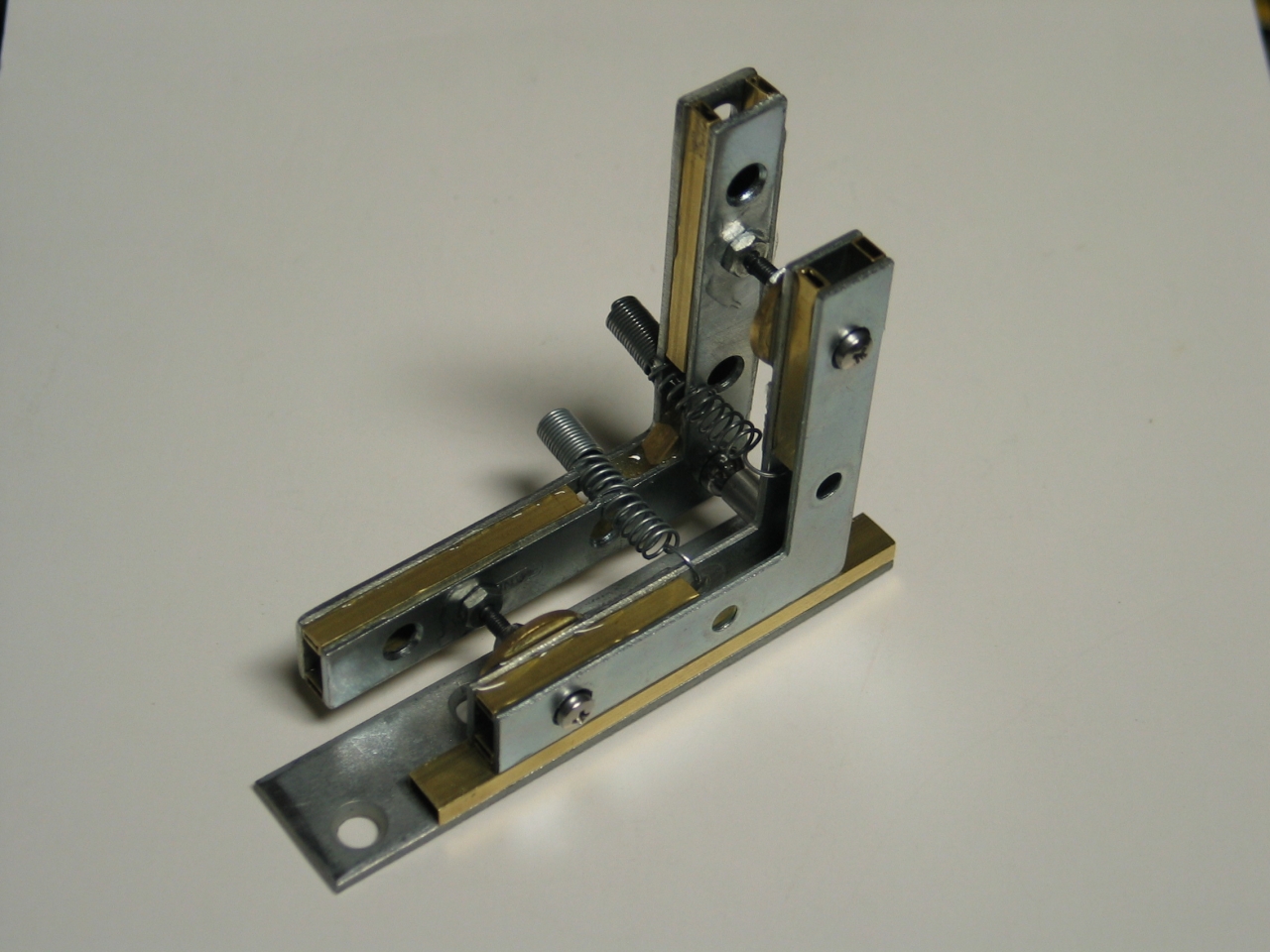
Here is the mount on a base, before I built and
installed the mirror cell:
The mirror cell for this mount consists of 3 main
pieces, as that was about the easiest thing I could put
together from what I had on hand. 2 of the pieces are a
faucet aerator and adapter, as pictured above; the third
is another adapter. I also used a metal washer or two,
some o-rings, and a neoprene washer. These are to hold
the mirror in place and prevent it from contacting
metal, which might chip it.
Here are photos of the cell being glued into place,
with both adapters on & the aerator body removed
(for balance), and of the completed mount:
I have tested this mount, and as far as I’m
concerned, it is a decent and usable design. As with the
earlier versions, it can be built entirely from parts
and materials that are available at hardware stores and
hobby shops, though some of you may have to go to a
bicycle store or some other odd place for small steel
balls; and it can be built with nothing more than a
jeweler’s saw, a file or two, a hobby knife, and
some sandpaper, though I will admit that it is rather
more convenient if you can drill a few holes fairly
accurately. (You do need to drill at least one hole in
order to glue the balls on the ends of the adjustment
screws, but it should be possible to build a jig to do
that from a few pieces of paper, which would eliminate
all need for drilling. I may write that method up and
post it here at some point, if I have time.)
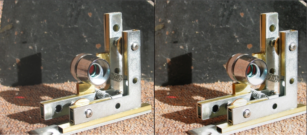
Here, in case anyone wants it, is an “X”
(cross-eye) mode pseudostereo (that is, I took the two
photos separately) macrophoto:
...And now, on to the next item in this set.
(23 August, 2007)
In connection with one of my projects, I find that I
need some translation stages. (I need to position a
pinhole for a spatial filter, and I need to position one
or two iris diaphragms.) In order to fill these needs I
have designed a translation stage that can be built for
one or more axes, uses only materials that are available
at hobby shops and hardware stores, and does not require
any machine tools beyond a Dremel® or other rotary
tool. You will, however, need a jeweler’s saw
or something similar; a very small bandsaw might do.
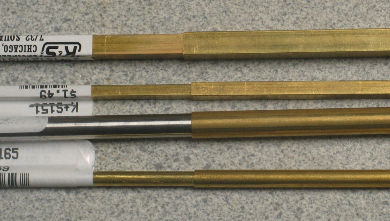
Here is the basic structure I am making use of; I
bought these at a local hobby shop:
In each case, what we have is a tube that fits very
nicely over either a rod or another tube. With a square
cross-section, rotation around the axis is not much of a
problem: the fit is fairly decent. Still, if you need
precision, the square configuration probably has more
wiggle-room that you are going to be comfortable with.
In order to use the round cross-section you must resort
to low cunning, and use them in pairs. The easiest way
is to glue the two sleeves together; they have to be
very nicely parallel, but that should be fairly easy to
arrange. Another advantage of the circular cross-section
is that the rods, especially in pairs, are considerably
stiffer than hollow tubes. A third advantage of doing
things in pairs is that you can push (or pull) the rods
apart a little at their ends, which should eliminate
most of the runout/wobble.
You do not have to use the concentric structures
I’ve shown above; it is perfectly reasonable to
use pieces of angle iron (or of aluminum angle
extrusion) that ride on the rods. (I would, though, use
stainless steel rods rather than any type of thin-wall
tubing for this version.) You will, of course, have to
make sure the riders are held onto the rods on any axes
where gravity won’t hold them on for you. It is
also probably a good idea to be sure that rods and
riders are all as straight as possible.
Here is a rude ASCII-pic cross-section. The /\
structures with the little ^ “hats”
are the angle pieces; the Os are the rods or
tubes.
(The hats should actually be integral with the /\
structures, but of course ASCII is not conducive to
the accurate representation of detail.)
You could put a “floor” between the two
riders to make it easy to mount things on them, just as
you can with the concentric structure:
Back to the main flow, and to actual construction...
My initial needs are not stringent, and for a first
prototype I am going to make a 2-axis stage using the
uppermost pair of square tubes from the photo, above.
(The outer sleeve is 1/4" square and the inner is 7/32",
which should give me reasonable strength and stiffness.)
I would like to have perhaps half an inch of travel or a
little less, so I am making the sleeves 2" long and the
shafts 2.5" long.
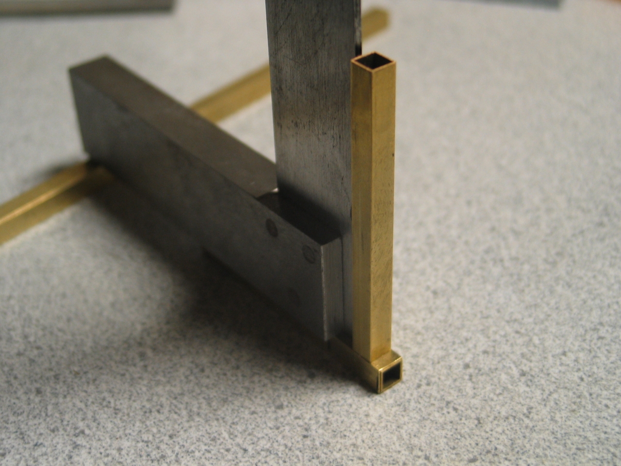
It is rather important to ensure that the second axis is
orthogonal to the first one. Fortunately, I have a small
machinist’s square here. If you don’t have a
square you can acquire one, or find something that has a
reasonably accurate right angle. For most purposes we
are not talking about microradians.
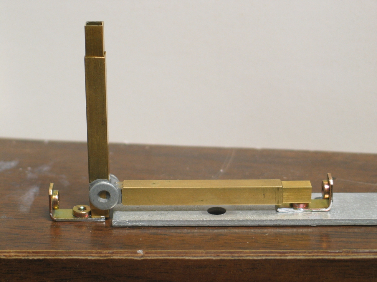
Here is a photo of the setup, with the second-axis shaft
in position to be glued onto the first-axis sleeve:
Once I have the two axes connected, I need to be able to
adjust their positions. Zimmerman’s (mentioned
above, in the section about the mirror mount) carries
M3-0.50 screws and nuts, which suit this application;
0.50 mm is just under 0.020 inch, and that is probably
adequate precision for positioning an iris diaphragm.
When I build the 3-axis stage for the pinhole of the
spatial filter, however, I will need either micrometer
heads, the differential screw arrangement that is
further down this page, or both. (I think I have only
two small mike heads, which leaves me using a
differential screw for the third axis.)
To return to the prototype: rather than letting the
first-axis screw push on the base of the second-axis
shaft, which would reduce the usable travel of the
second axis, I am thinking about gluing a small stop
into place on the first-axis sleeve.
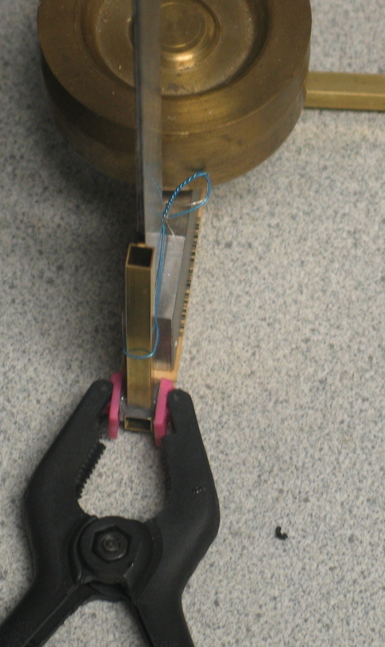
(Evening of 24 August, 2007)
I have checked to see where I need the iris on the
laser, and I have epoxied the shaft of axis 2 onto
the rider of axis 1, using two small washers as
gussets. Here are two slightly blurry (sorry) photos
of the gluing setup, showing the square I’m
using as a reference
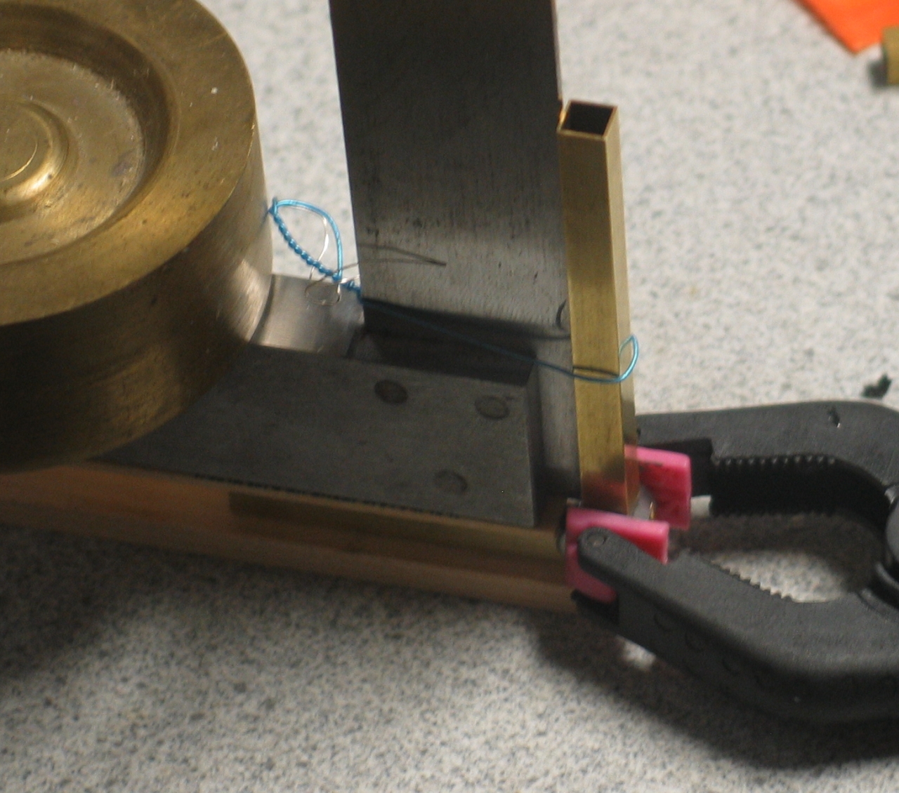
(The little spring clamp is holding the washers in place.)
Notice that the square is generating 2 axes of
reference. The shaft is in contact with it all
the way up, which is one axis; in addition, I
centered the square on the bottom shaft as well
as I could by eye, and then I centered the top of
the vertical shaft against the square as well as
I could. (Again, my needs here are not terribly
stringent; if they were, I would have acquired
at least one more square, and possibly two.)
I have also purchased some small springs, to use as
tensioners; still thinking about how to attach those,
how to mount the adjustment screws, and how to mount
the stage on its base. I will have to put the base on
a pedestal for this laser, but that’s a separate
issue.
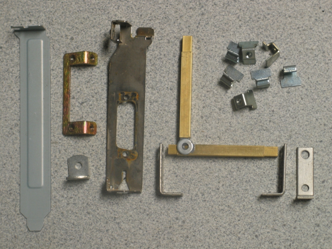
I need angle brackets to hold various pieces of this
stage. Here is the glued assembly for the two axes
(with riders on the shafts), as well as some possible
angle brackets and sources:
As you can see, old computer parts turn out to be
valuable in new ways. Here is the first foot being
glued onto the stage:
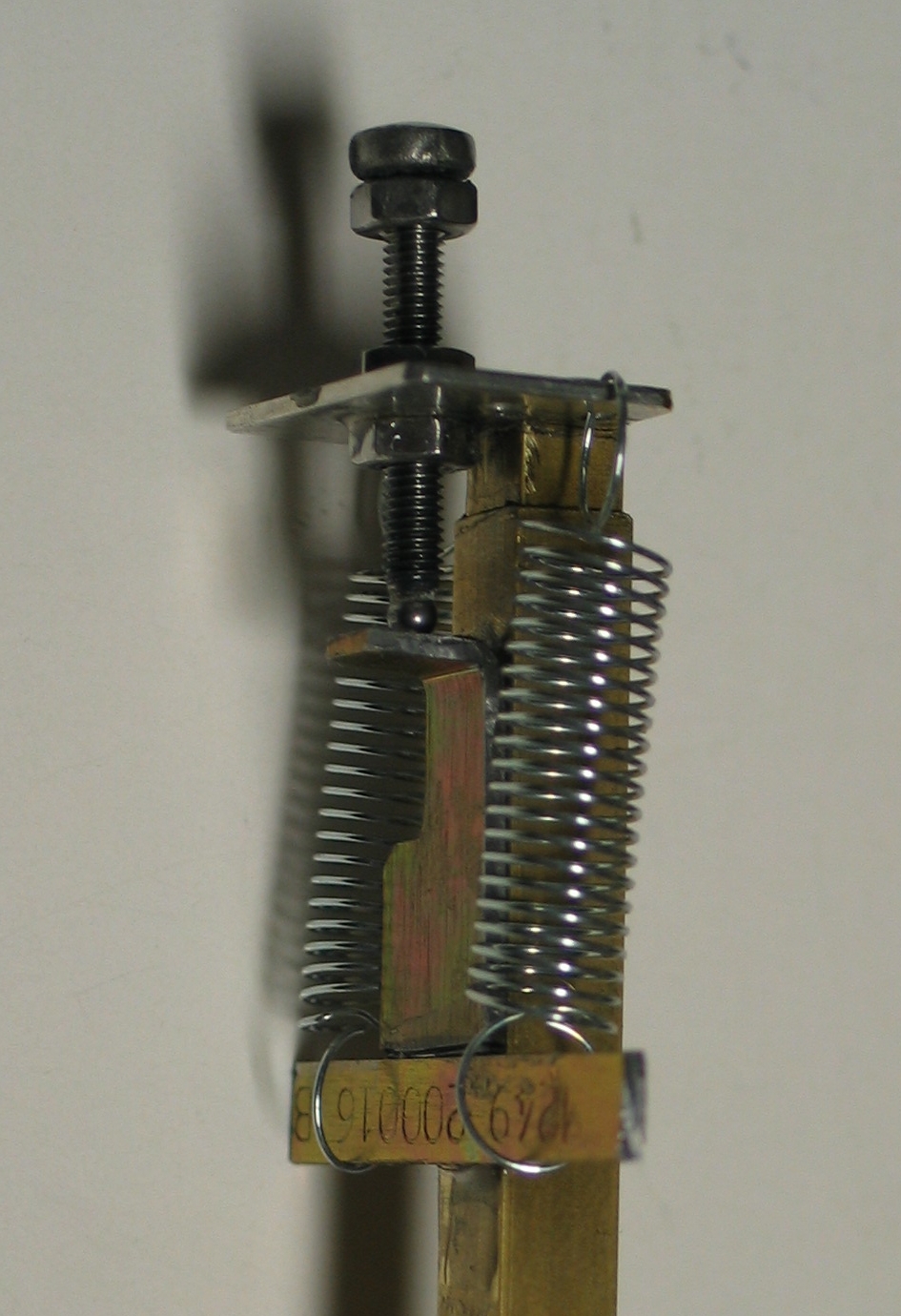
Here is the control mechanism for the Y axis:
(I epoxied a plate with some holes in it on top of the
shaft, and attached the relevant items. I put an L on
the traveller, with a bar behind it for the springs to
attach to. I also added a stop nut on the adjustment
screw, because if I try to push the axis past its travel
limit I will detach the plate from the end of the shaft,
which is a Bozo No-No and is severely deprecated.)
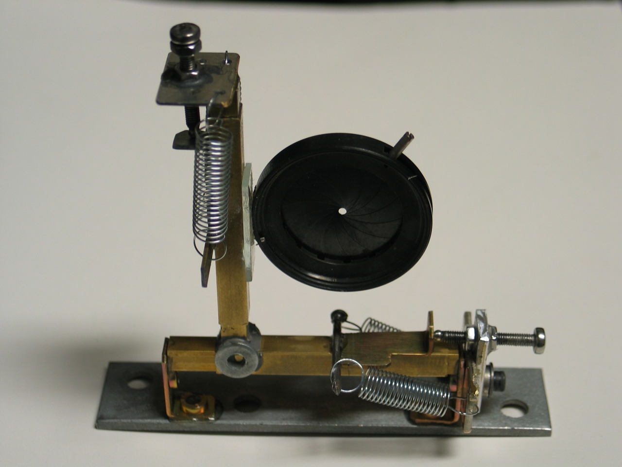
Here is the completed stage. As you can see, I did the
control for the X axis slightly differently; but the
principle is the same. (I will probably add a stop nut
on this axis to match the one on the Y axis, though
because of the construction it isn’t really
necessary.)
This device is now ready to go into the laser. If
and when I get any results worth reporting, I will
add a link to the relevant page.
Two further notions:
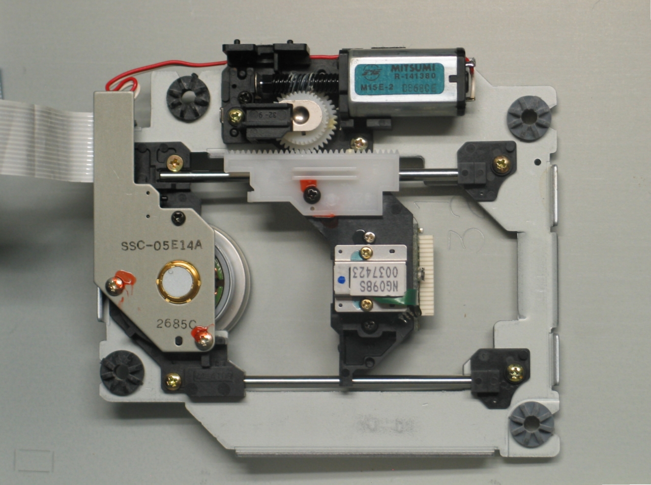
1) You can always acquire a single axis by disassembling
a dead CD-ROM or CD/DVD player. The laser head rides on
rails, at least in the players that I find inside
computers. Here is a photo of an assembly that I took
out of an ancient Mitsumi ROM reader; it still has the
disk rotation motor on it, but that was easy to remove.
The laser and other irrelevant parts of the head should
also be easy to get rid of, if you don’t just
decide to ignore them.
This has the advantage of giving you an actuator, though
you may choose not to use it. You could fairly easily
build a multi-axis stage from these if you don’t
need it to be particularly compact. Alternatively, you
could use one of them as the lowest level of a 2- or
3-axis stage.
2) A chap named Brian Manning has made his own version
of the ruling engine that appeared in the Amateur
Scientist column of Scientific American in April, 1975.
His page about it is a gem.
(25 May, 2007)
It turns out that there is a nifty way to make a
differential screw — you butt two screws together
(with a compliant coupling, unless you are abundantly
certain that they are rather precisely collinear and
well aligned with whatever you are using them to move),
and use a fixed nut on one & a travelling nut on the
other. You can think of the screws as being there
primarily to connect the nuts together; the fixed nut is
the reference, and the other is the driver. In practice,
it’s not quite as simple as it sounds; but it is
nonetheless a remarkably easy way to permit relatively
fine adjustments. (We are not talking single wavelengths
of light here. That takes slightly more advanced
techniques, or really careful construction, and
good temperature control.)
I desperately wish I’d made this up, because it is
so ripping brilliant, but I didn’t; someone
told me about it, perhaps a decade ago. Somebody almost
certainly has (or had — probably long expired) a
patent on it.
[I’m going to assume, for the purposes of this
explanation, that the coarse screw rides in the fixed
nut, so that the final motion is “forward”
when you rotate the coarse screw clockwise. There is,
however, absolutely no reason why you would have to do
it that way if you didn’t want to.]
When you rotate the coarse screw, it moves in the
reference nut. That pushes (or pulls) and rotates
the fine screw, which thus pulls (or pushes) the
travelling nut almost back to where it was before you
rotated the screws. How much of a change in position you
get depends on the ratio between the thread pitches. If
you have, for example, M5-1.0 and 10-24, you’re
looking at about 1.4 mm for 24 turns, which is quite
decent. If you can make everything out of the same
material, and if you can control the temperature
in the room precisely, you may want to try M5-0.8
(fine pitch) and 10-32, which gives you 0.2 mm travel
for 32 turns of the 10-32 screw. (It’s 0.8 mm/turn
vs 0.79375 mm/turn.)
I don’t need anything like that kind of precision
for my current application (positioning the ends of the
electrodes of a TEA nitrogen laser), so I went with a
much bigger difference. My coarser screw is 10-24 NC and
the finer one is 10-32 NF. The 10-24 moves forward 1" if
I rotate it through 24 turns, and the 10-32 pulls the
travelling nut backward 24/32", which = 3/4", so the
pushrod I’m using as an actuator ends up going
forward by 1/4".
That is, 1 turn gives me a little over 10 mils, and one
“hour” (if you think of the thing in terms
of a clock) gets me just under 1 mil.
Here are two preliminary photos, with the electrode not
yet attached to the pushrod:
You’ll notice that the fixed and travelling nuts
are composed of two hexnuts each. This is a crude
anti-backlash mechanism. To do it right, you actually
have to make an extra doubled nut & run it up and
down the screw a few times with some extremely fine
abrasive, so it takes out all of the irregularities in
the threads. Then you set that nut aside, remove
ALL of the abrasive from the screw, and put on
the real anti-backlash nut. I’m not going to
bother, and I’m not going to tighten up the
anti-backlash very much — I just want to take out
a little of the slop.
Speaking of slop, this version is probably not really
accurate for anything as tiny as 1 mil, because there is
only RTV [in this case, aquarium caulk] between the nuts
I’ve glued to the ends of the screws to provide
sufficient area for good coupling; in order to get
enough stiffness for real accuracy, I would have to make
sure they were always in metal-to-metal contact. (Care
to think up a nice simple way to achieve that and still
have a compliant coupling that allows for [or prevents]
all of the possible misalignments? Definitely a fun
project.) OTOH, once the RTV stiffens up fully, it
should certainly be good enough for folk music.
It is not trivial to figure out the details on one of
these, and I have probably made some mistakes here, as
this is really the first time I’ve tried to build
one; but I’m sure that a bit of hands-on
experience will get me where I want to go. I don’t
really need even as much as 1/4" of travel for the laser
I’m working on right now, which helps.
(24 August, 2007)
I noticed that
The Surplus Shed
has some inexpensive diffraction gratings, so I bought
one and used it to build a little hand-held spectroscope
out of Schedule 40 PVC plumbing pipe and fittings. Here
are two photos, showing the way I constructed the ends:
I have angled the slit, so that one end is a bit wider
than the other. I hope this will let me see some of the
Fraunhofer absorption lines in the spectrum of the sun.
Note, btw, the fact that the slit end consists of two
threaded fittings. The one that the slit is mounted on
screws onto the one that is glued to the main tube.
Doing it this way lets me line up the slit with the
grating easily. (It also lets me replace the slit with
an adjustable one, should I ever decide to do so.) The
two pieces of flat plastic under the razorblades are
there for two reasons: first, to exclude extraneous
light that would otherwise go around the back edges of
the blades. Second, the blades are not actually wide
enough to reach the edge of the fitting, so I had to
support them. You can also see a small piece of wood at
the edge, where there is a space between the two flat
pieces. Again, it is there to exclude extraneous light.
The other end may be slightly unusual; the hand
spectroscope I had when I was a kid was simpler —
it had both ends cut off square, so its grating was
parallel to its slit, and there was nothing past the
grating at the eye end. I set the grating of this one at
the angle that gave me the brightest spectra, and I
added the extra tube to prevent other lights from
interfering with my view of the grating. (Since this
picture was taken I have changed the angle at the
end slightly, so that if I hold the filter on the
front of the camera up against the tube, the lens
points more or less directly at the spectrum I’m
trying to photograph.)
Here are a few spectra. First, a halogen bulb produces
the expectable continuum, which may let you get a
sense of the bands that the camera’s sensor
is picking up. Then the discharge inside a HeNe
laser. Third, a compact fluorescent bulb; and
finally a spectrum of one of the HID headlights
of my car:
(The middle two are somewhat underexposed;
the left edge of the HID headlight one is grossly
overexposed.)
The grating is definitely not the greatest I’ve
ever seen, but it didn’t cost very much, and it
clearly works. (Note, added on 15 September, 2007: I
have purchased what I hope is a better grating on eBay,
and if it works out well I will post a revision here.)
The new grating does, indeed, work pretty well, but
it will require two photographs to cover the visible
spectrum until and unless I shorten the sighting tube.
This is because the grating, a rectangle that is about
twice as long as it is wide, is ruled with the lines
going the wrong way. At some point I may acquire a
better one, but this one serves reasonably well for
just looking at the spectra of reasonably bright
sources.
(09 January, 2011, ff)
I have been building some gas lasers, or trying to, and
as part of that effort I have had some difficulty
achieving a sufficiently good vacuum. I am fairly sure
that the roughing pump I’m using is good enough,
but I found that I couldn’t even get the laser
head down to 1 Torr.
Part of this appears to be a materials issue: silicone
rubber caulk appears to continue to outgas for quite
some time after it is apparently fully cured, or perhaps
it allows some air to diffuse through; either way, I
think that it is not particularly suitable for use in
vacuum systems, even crude ones.
There is a special epoxy called Torr-Seal, which is good
down to about 1.0X10⁻⁹ Torr; it is rather
expensive, but it does work. If you look on the Web, you
will find claims that Loctite’s Hysol 1C (which is
far less expensive) is very similar, but I don’t
see any actual performance test results. My current
conjecture is that just about any properly-mixed epoxy
should be good down to better than 1 micron
(10-3 Torr), and I am guessing that J-B Weld,
which contains fillers of some sort, may be slightly
better than most.
Then there is the question of teflon pipe tape. How good
is it? It certainly appears to be adequate in the
low-milliTorr range, which is good enough for me, at
least for now. I am, though, curious about whether it
can be used at lower pressures.
In any case,
here is a page on my rebuild of the manifold
for this setup.
To the Joss Research Institute Website
To my current research homepage
My email address is a@b.com, where a is my first name
(just jon, only 3 letters, no “h”), and b is joss.
My phone number is +1 240 604 4495.
Last modified: Wed May 10 15:03:28 EDT 2017
Version 3:
It’s Time to Rethink (Again)
Sidebar: A Brief Note about HeNe Lasers
Revisionist Tendencies
A Simple Translation Stage
Sidebar: A Slightly Simpler Alternative
     ^  ^
    /O\/O\
     ^     ^
    /O\___/O\
A Simple Differential Screw
A Simple Hand Spectroscope


Improving a Small Vacuum System
the Joss Research Institute
Contact Information: