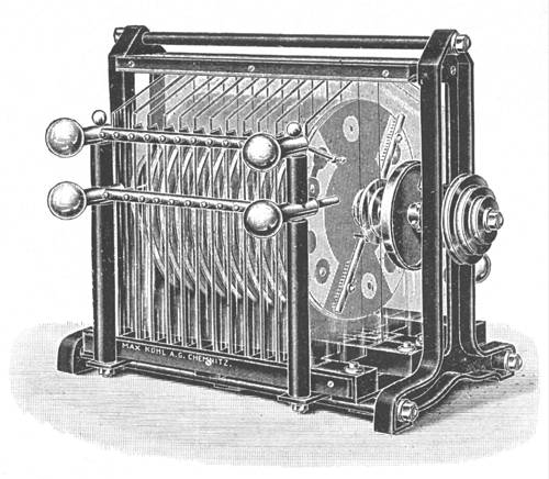
I found all of the rotating-disk electrostatic “influence” machines rather difficult to understand, btw, until I wrote my own version of this French page about the Wimshurst machine. In the course of making my translation I found that I needed to describe the action a bit more fully than the original page did, so I added specific notes about what happens when a sector is at various positions, and I also added a section about induction (formerly called influence, which may possibly be a better term). The result is really more of an adaptation than a translation.
The act of writing that adaptation was what really
permitted me to understand the way the machine works,
and I note this because it is something many people have
found: if you want to understand something better, try
explaining it to someone else. This will also let you
know, in a big hurry, just how underappreciated teachers
are in the US (or wherever you are). Technical writing
is also difficult and frustrating; one of the few
compensations is the fact that the writer gets to
understand the material better by documenting it. If the
writer is good (and lucky), other folks also get to
understand it.
Because the Voss machine has only one rotating disk,
there is no reason why its inductors need to be mounted
on a second disk; any flat plate of appropriate size (or
even two flat plates) will do. For convenience, my
machine uses two glass plates, each 6" wide and 15"
tall, spaced 2" apart. This gives me a 1" margin beyond
the edge of the rotating disk, which is about 12"
across. Because my design does not use a second disk,
and because we now have epoxy glue, I actually
don’t think I need as much margin as I have
provided; but it keeps the frame out of the way, and a
bit of extra isn’t likely to hurt anything.
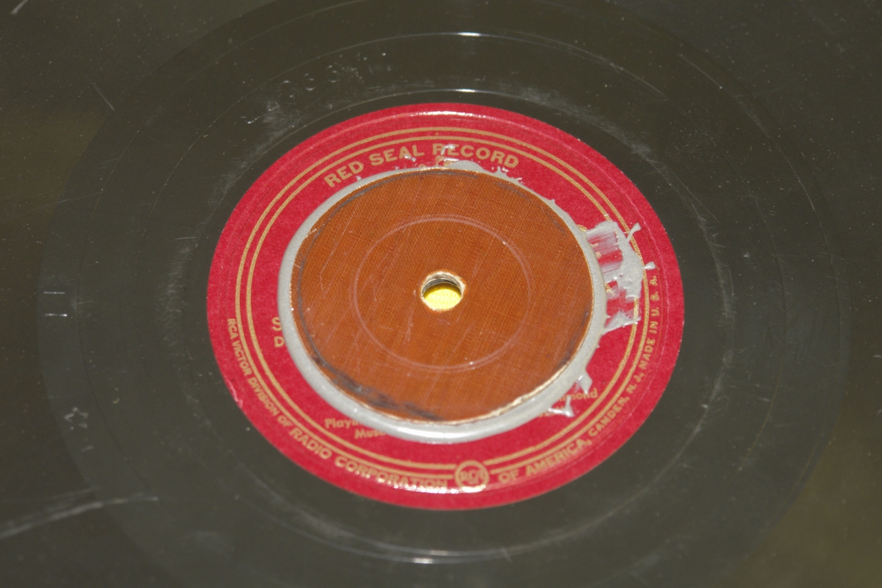
Before we get to the inductors and appropriator brushes
and their mountings, however, there is a crucial issue
to be dealt with: how do you mount a flat disk on a
shaft so that it doesn’t wobble as the shaft
rotates? The general question is compounded here by two
factors, the first of which is that the disk I want to
use is a very old phonograph record, which is probably
made of shellac with various arcane additives, and is
quite brittle. (I know this because I have broken a few
of them...argh.) The second is that the entire device is
going to be exposed to high voltages, and I don’t
want to provide extra paths that might limit the
performance of the machine, so I would like to avoid
materials that are highly conductive. (In fact, I am not
entirely happy about the fact that the main shaft is
made of metal. We’ll just have to see whether that
works out well.) One other important issue: I want to be
able to disassemble the mount, so that I can replace the
disk if I either damage it or decide to try a different
one.
I thought about this for some time, and solicited advice
from various folks. Our Range Safety Officer, Lisa
Peoples, suggested a 3-piece collet with a retaining
ring, and after I thought about that for a little while
I decided that it was a fine notion. (I’d been
thinking about structures to hold the disk; she, on the
other hand, was thinking about structures to hold the
shaft. I mention this as a reminder of how
important it is to keep all of the options open, and to
avoid getting stuck inside a box that is smaller than
the actual problem.) I modified her original suggestion
to use two pieces instead of three, which makes it
easier to build, and then modified it again to maintain
the alignment of the pieces, because I want the disk to
be pressed against a [cushioned] flat surface. What I
eventually decided on is shown in the photos below. It
is not by any means original — you can see similar
mountings on old water-wheels and in various other
places.
The disk is decently flat (I chose it from among a
rather large number that I purchased at the Friends
of the Library Book Sale), so it should be reasonably
straightforward to trim out the [inevitable] wobble; but
because it is so delicate, I have strengthened the face
that the wobble-adjusting screws will press against by
gluing a piece of phenolic circuitboard material onto it.
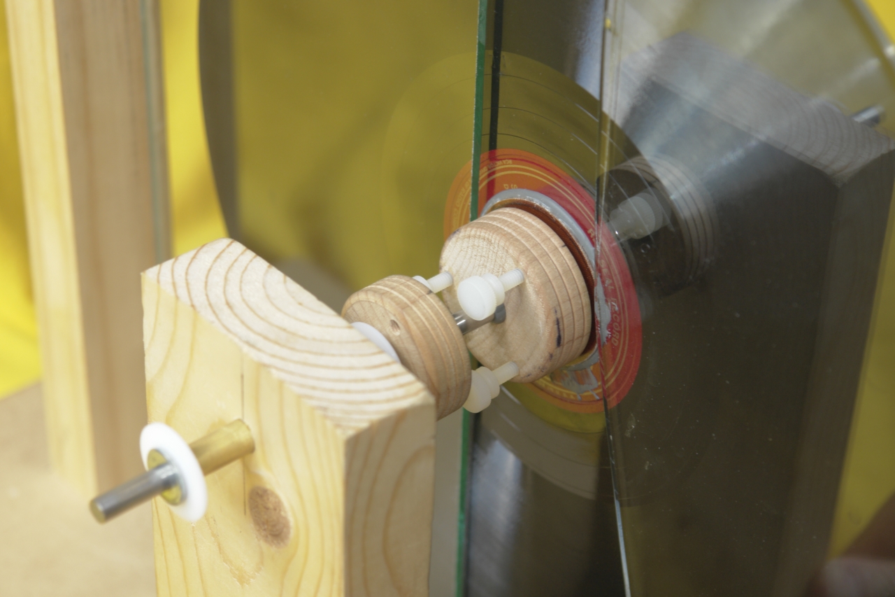
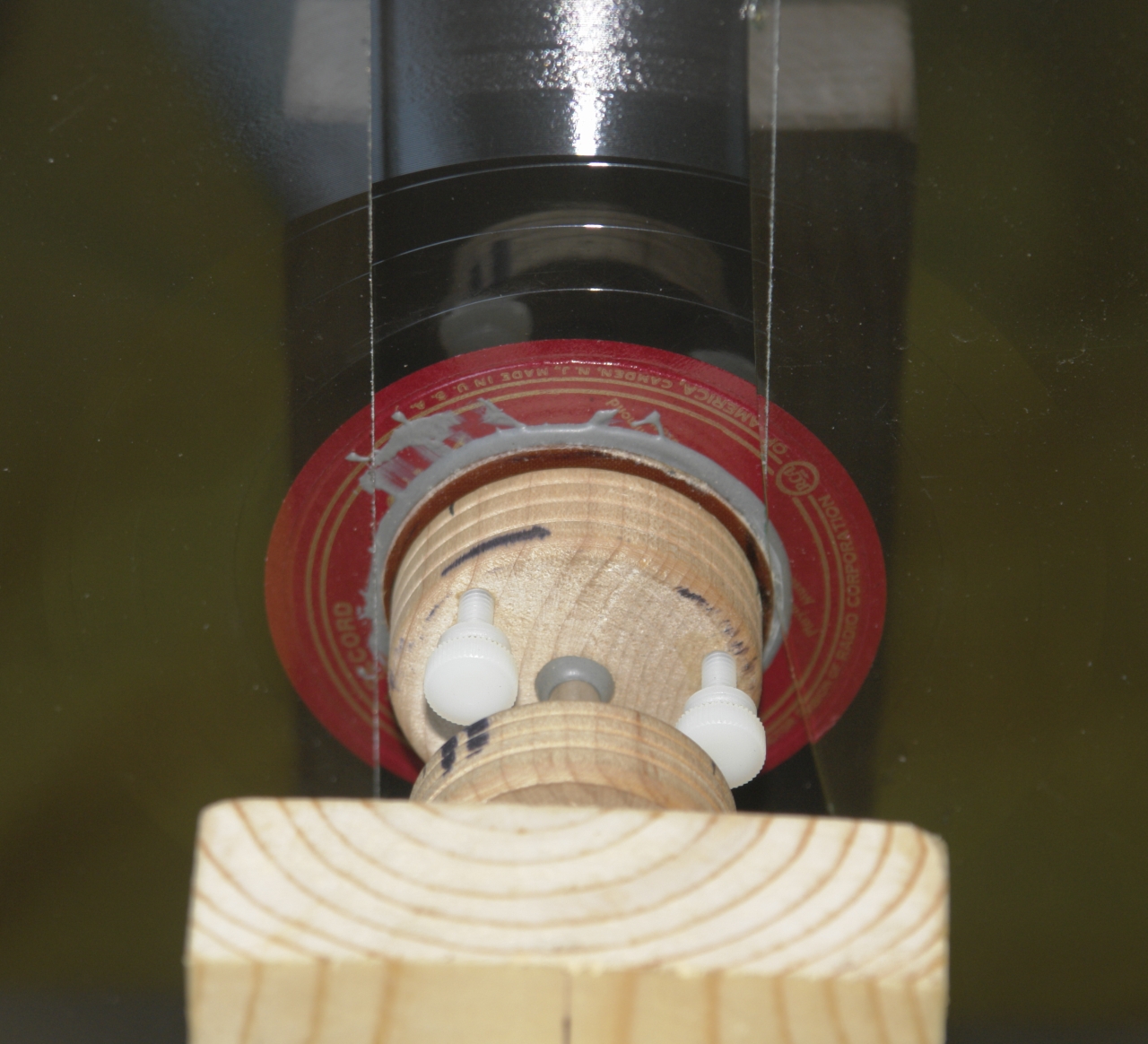
Here are some preliminary photos of the wobble adjuster,
the collet, and the pressure plate on the disk. The
metal screws in the collet were temporary; I have since
replaced them with nylon ones.
If you decide that you want to build a Voss or other
static generator, there is no reason why you need to do
it the same way I did; that said, however, some people
may want a bit more information about the collet,
because it seems to be a decent way to hold the disk in
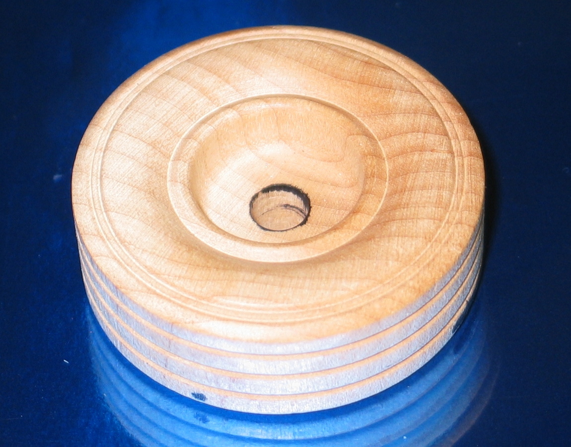
place. I made it from two small wooden wheels that I
bought at a hobby shop. (These typically come in
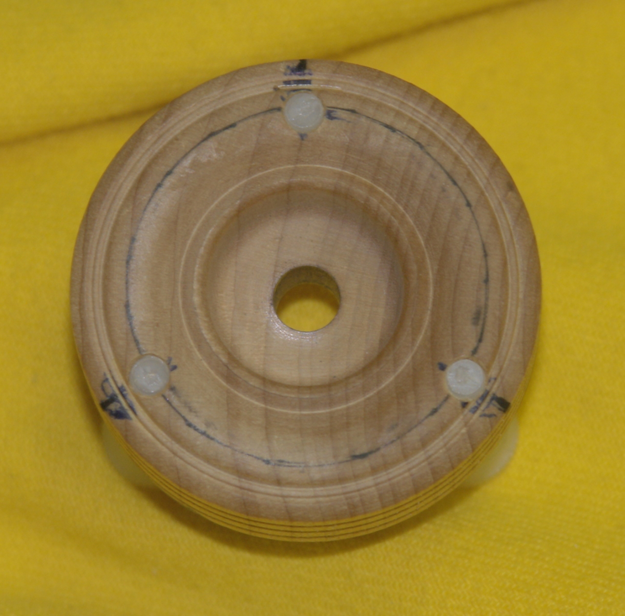
packages of 4, which is handy.) Here is one of the
wheels:
The back side is flat and very plain.
I slid two of these onto the shaft with their flat
sides apart for maximum stability, and used J-B Weld
epoxy to glue them together. That gave me a disk of
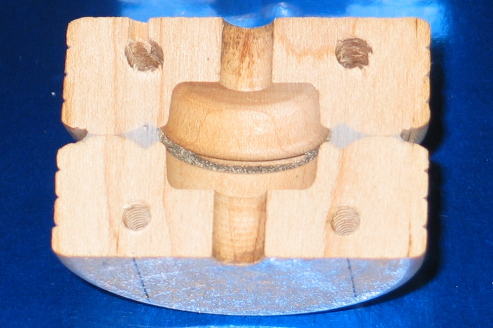
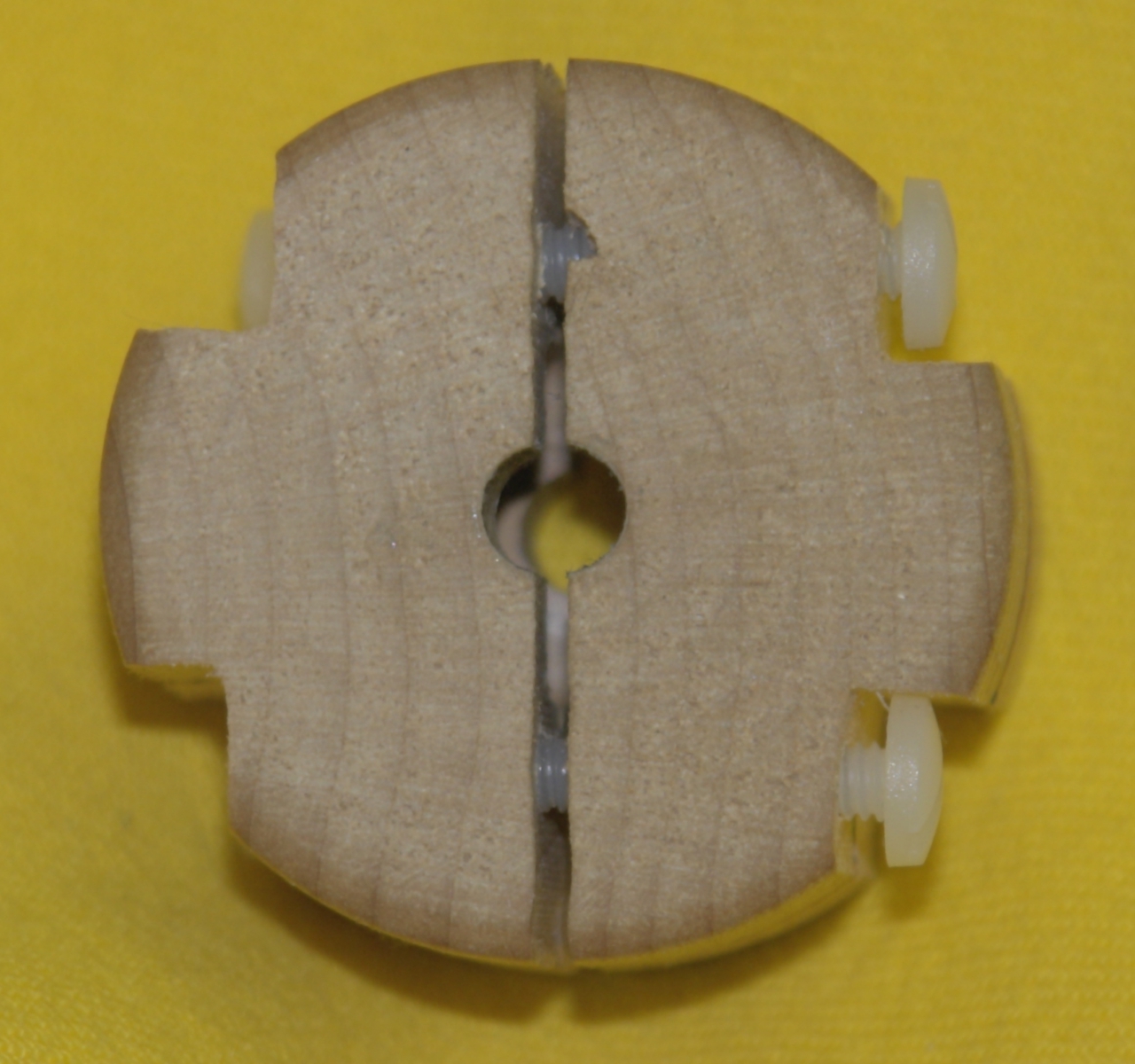
double thickness, prealigned to the shaft. Here is a
cross-section:
(I did not take photos as I was doing all of this, so I
was obliged to make these illustrations from the completed
piece.)
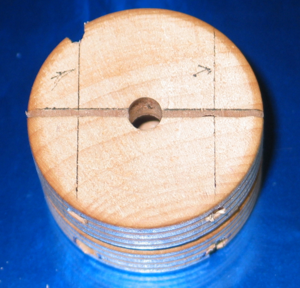
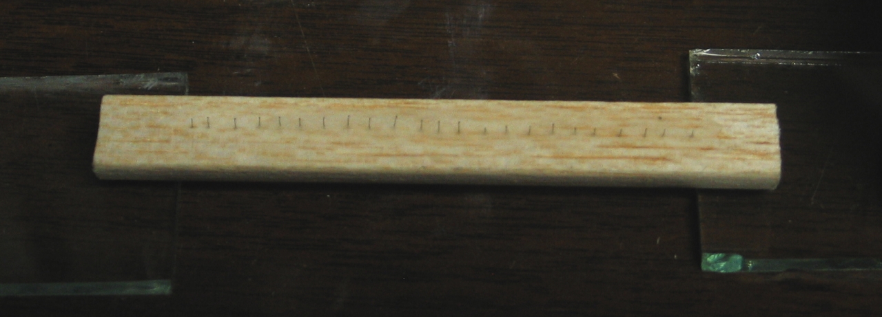
Then I drew a line across one face of the disk, through
the center hole (the horizontal line that separates the
two pieces, though I did not saw them apart
at that point), and two more lines, to indicate the
positions of the screw holes, at right angles to the
first one:
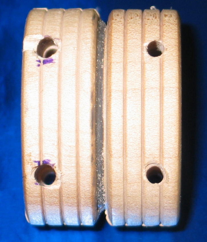
Then I drilled 4 holes into the wheels, so that they
were in wood all the way through, and some distance away
from the shaft, using the lines as guides. You can see
the holes in the cross-section, above, and here:
Originally, these holes were all the correct diameter
for a tapped 8-32 hole. After I drilled them I sawed
through the middle of the collet, which gave me two
halves, each of which had 4 holes in it. Then I drilled
out 4 of the holes to the body size of the 8-32 screw,
and tapped the other 4. I built this collet with two
screws facing up and two facing down, but I doubt that
it makes any real difference.
(10 July, 2007)
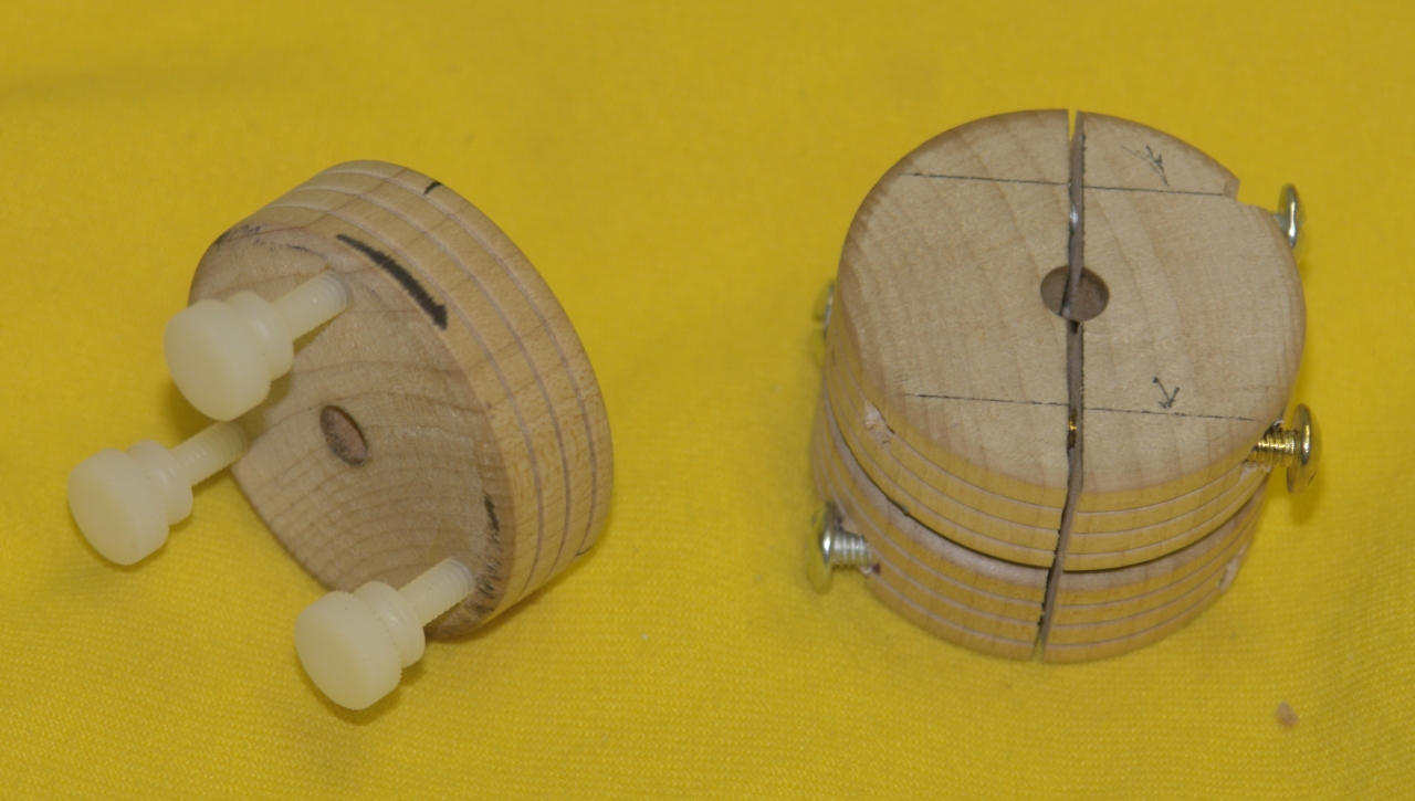
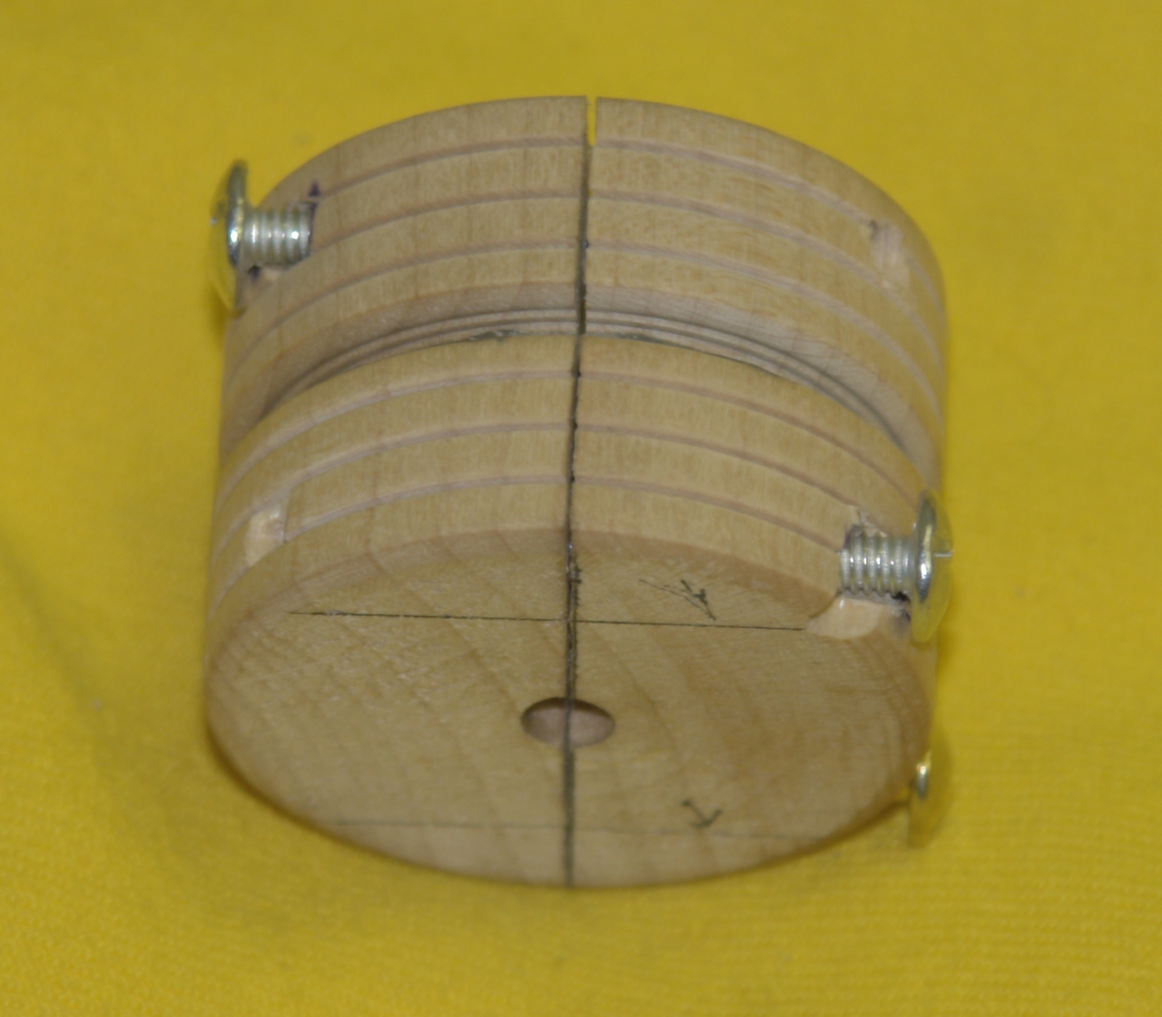
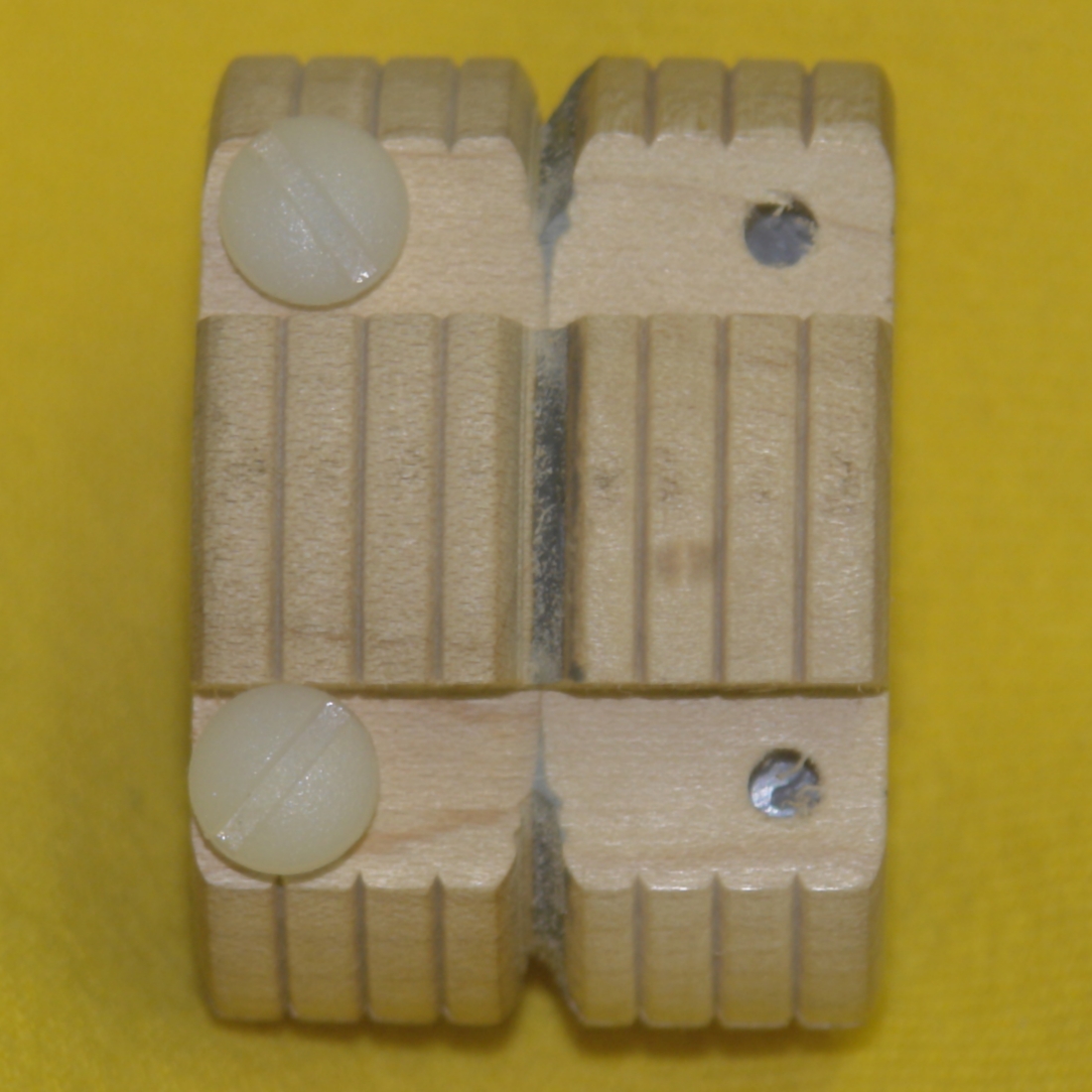
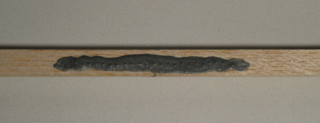
I noticed that the screws were bending when I tightened
them, so I went back to the bandsaw and created flat
places for the heads to rest on. Here are two views of
the modified collet:
(06 July, 2007)
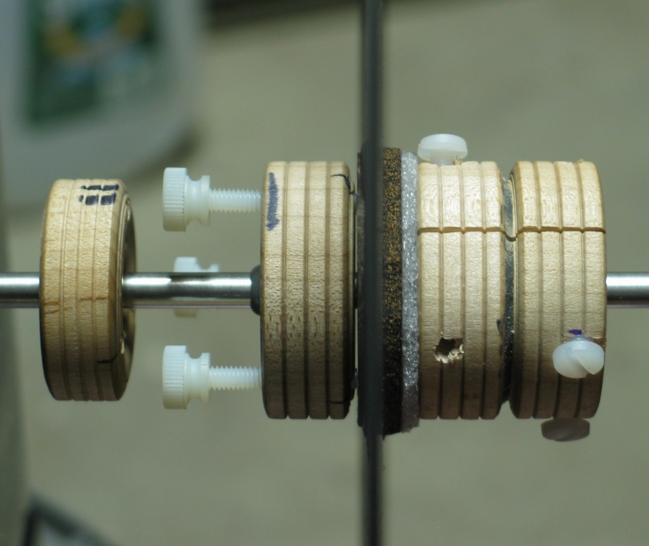
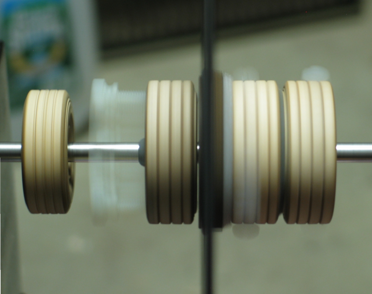
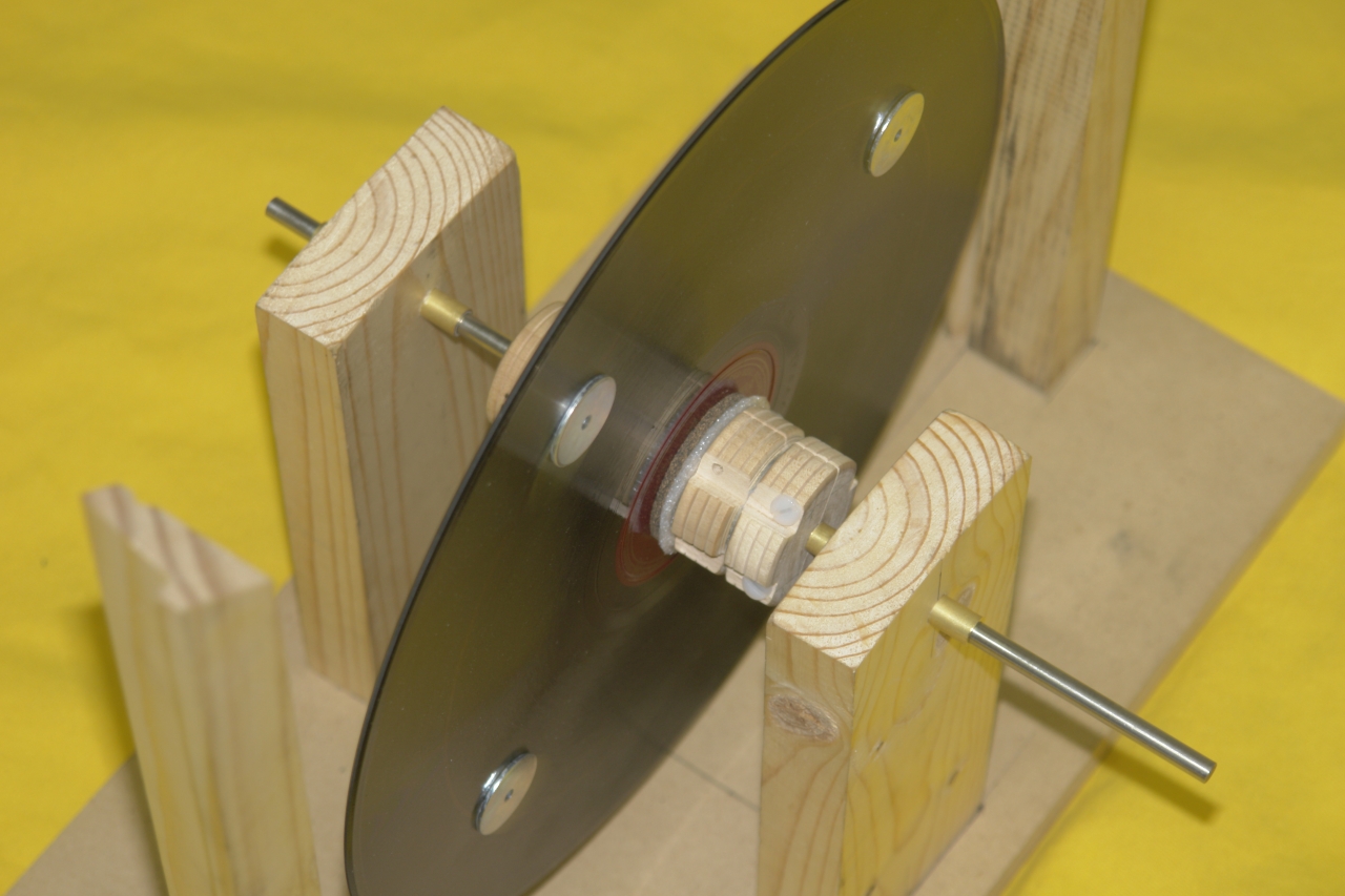
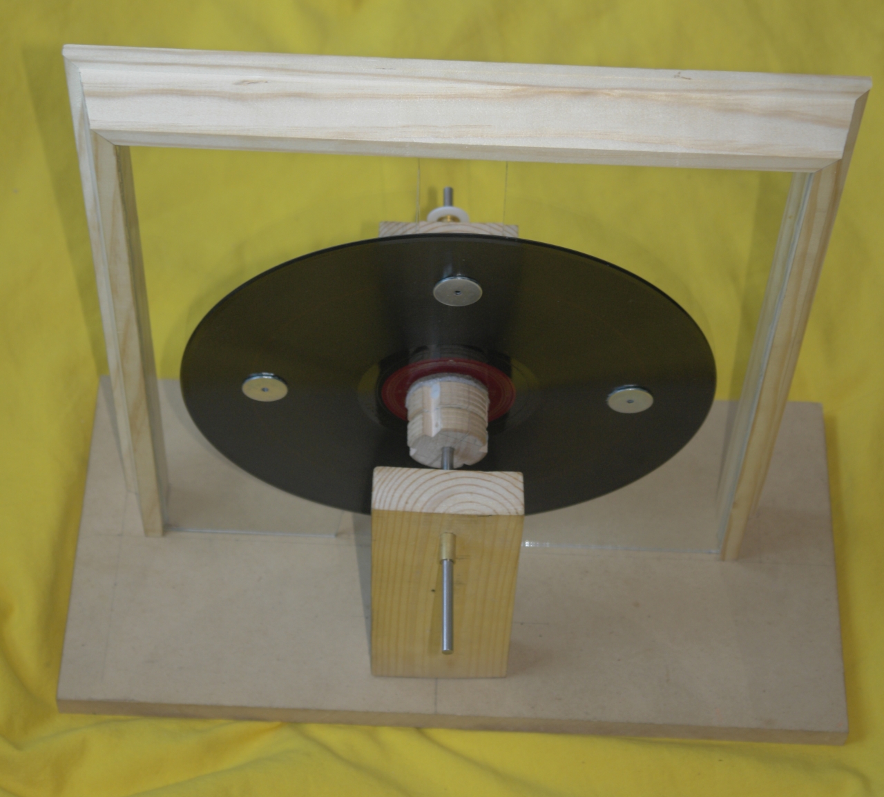
Here is the assembly, static and rotating, though not
yet in its actual bearings. You can see that there is
little or no wobble as the disk rotates. (The blurry
dark-gray vertical line in these two photos is the
phonograph record, which you are seeing edge-on.)
The small wooden wheel at the left is from an earlier
version of the design; I decided to use wheels of the
next larger size, both for better angular control and
because they have center holes of the correct size
to fit the shaft, and I don’t have to drill them
out.
As you can see, this setup appears to work decently
well. I trimmed out the wobble, and took the opportunity
to sand the edge of the disk with the handy Dremel tool,
so that it doesn’t move in and out quite so much
when the disk rotates. (The hole in the middle of the
disk is fairly well centered on the hole in the middle
of the pressure plate, but at least originally it was
not as nicely centered on the disk itself.)
The “front” of the disk, the side the
sectors will be on, is the one that faces to the right
in these photos. The inductors will be on glass plates
to the left of center, which is to say behind the disk.
My next step is to mount the shaft in its bearings on
stands that hold it up from the base. Then I need to
mount the glass plates on the base, trim them so that
they are parallel to the disk, and position the
inductors correctly on them.
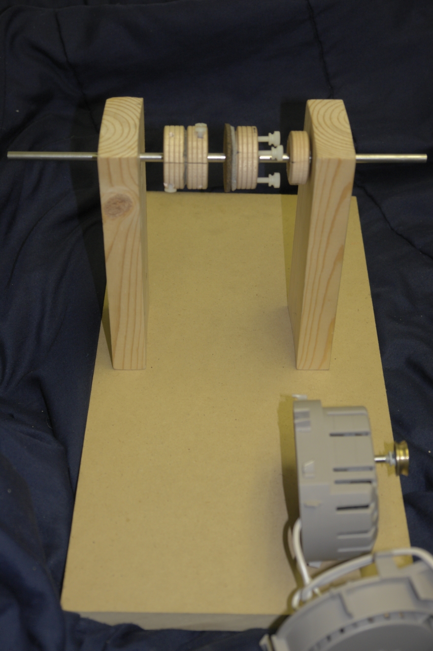
Here is an extremely tentative partial layout, with
the shaft simply inserted in holes in the vertical
posts; the bearings are not yet mounted.
We are viewing this from the other side: the front of
the machine, with sectors and combs and brushes, is to
your left; and the rear, where the drive pulley will
eventually be, is to the right. The disk (not present in
this photo) goes just to the left of center, and the
glass plates with the inductors on them (also absent)
are just about at the middle. The first drive motor I
intend to try is the small fan motor in the foreground.
It is slightly annoying that the longer end of the shaft
sticks out the front, but there is nothing preventing me
from sawing off the excess, and I will probably do so
later on.
One reason why this is so tentative is the fact that I
do not yet know how large some of the parts will be,
and that makes it difficult for me to decide where to
put the parts I already have. At some point, and I will
reach that point fairly soon, I’m going to grit
my teeth and start positioning things. I will probably
wait until I have the glass plates and their mounting
frame pieces cut, though, because those are crucial.
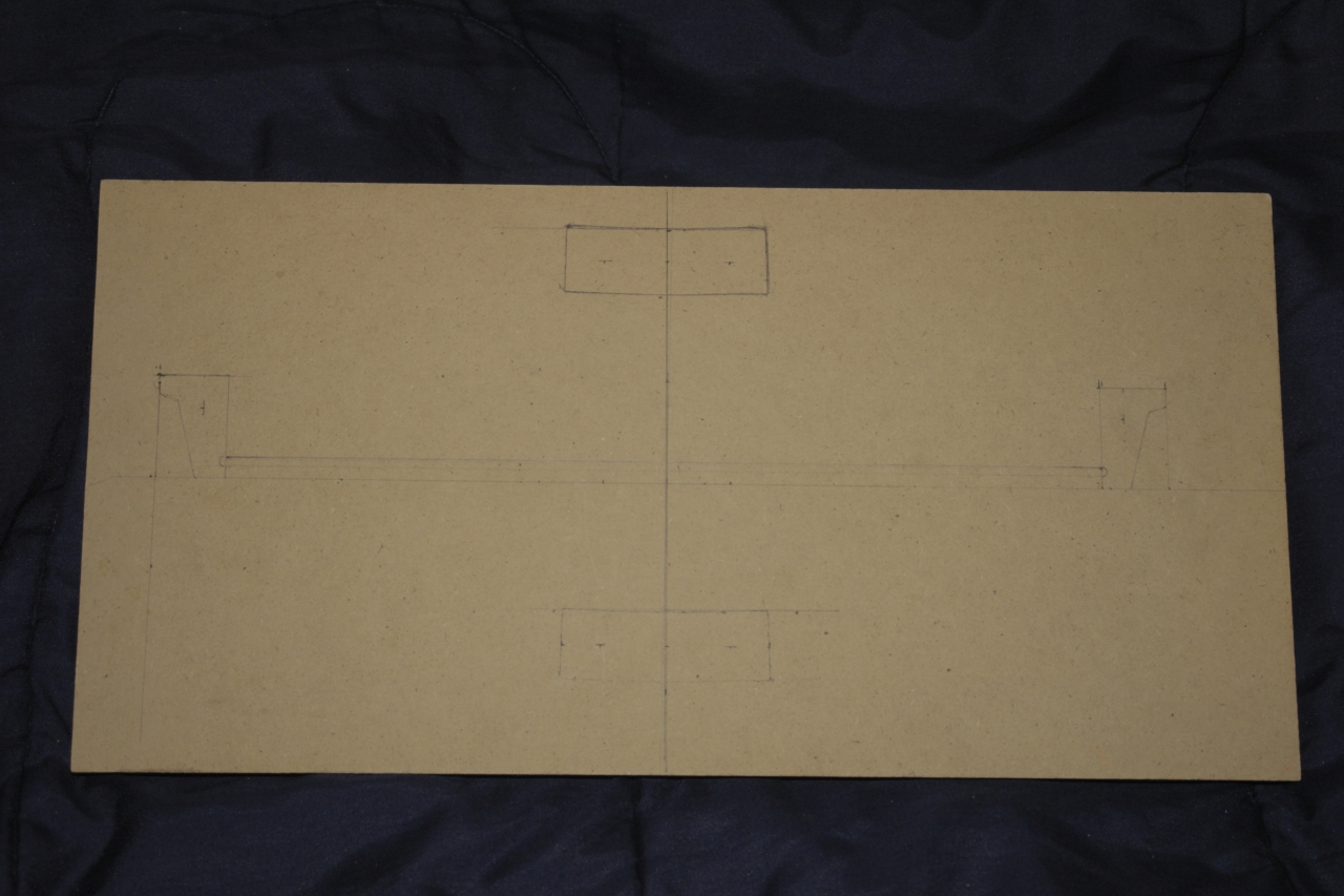
(09 July, 2007)
I have made the pieces of the frame that will hold
the inductor plates, and I have marked the base to
show where the plates and their frame and the posts
for the shaft will go:
As you can see, the posts for the shaft are warped.
Fortunately, they are fairly symmetric, and I am largely
ignoring the curvature.
I have just constructed a sleeve to use as a front
bearing for the shaft. It would have been nice to buy a
thick-walled tube, but I didn’t find one; I did
luck out, though: I found a tube that the shaft just
barely fit inside, a tube the first tube just barely fit
inside, and a third tube that the second one just barely
fit inside. I have epoxied sections of the three tubes
together to make a tube with a reasonably thick and
strong wall. I have a ball bearing that I am thinking
about using as the rear bearing, but it is very small,
and I’m not sure whether it will handle the forces
involved. I may just cut the sleeve into two pieces; it
is certainly long enough to make more than one bearing
out of.
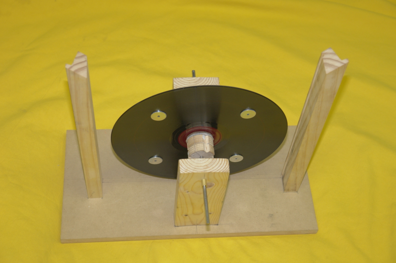
(11 July, 2007)
Here is a rather tentative preassembly, with the shaft
present (but not held in position, and possibly with the
disk facing the wrong way):
Having gotten this far, I can tell you that it is
extremely important to allow yourself some “wiggle
room” in all 3 axes. If you fail to do this, you
will almost certainly find that you can’t get the
shaft to rotate easily, and you can’t line up the
disk with the plates that the inductors are on. As
things currently stand I have not allowed myself quite
enough wiggle room, and I am going to have to increase
the amount.
(12 July, 2007)
I have attached the two glass plates to the frame that
holds them, but not to the base: I want to be able to
adjust the tilt if necessary. Here is an overview from
the front, and two details of the back, with everything
more or less in place:
The washer assembly that is visible at the left edge
of the middle photo is my tentative plan for setting
the distance between the disk and the glass plates.
When the machine is fully assembled the metal washer
will be held in place either by a small collet or
perhaps, for simplicity, by two cable ties wrapped
around the shaft. (Two instead of one because the
heads are wider than the tongues. It would probably
be best, actually, to use three.)
It appears that the tilt issue is not going to be much
of a problem; I expect to deal with it by putting a thin
shim under the front shaft post. My main concern now is
the fact that if I position the disk close to the glass,
the phenolic pressure plate scrapes. There are three
obvious possible solutions:
(The results are visible in the photos where I show the
inductors, below.)
In the course of assembling the frame, I found that
the crosspiece at the top was a bit too long. I went
back to the miter box and sawed the end off. It was
still too long, but only by a very small amount, so
I sawed the end off again. Here are two views of the
resulting chip; notice how nice and smooth the cut
surface is:
The chip is thin enough that it is quite translucent:
The inductors are crucial to the operation of the Voss
machine. They are usually paper, often with a metallic
strip underneath to help compensate for changes in the
conductivity of the paper with humidity, but occasional
machines have inductors made from metal foil. I have
made mine from Origami paper, of a particular type that
has foil on one side, as this obviates the necessity for
separate foil strips. The inductors are connected to the
appropriator brushes, which (as I have already
mentioned) contact the raised bosses on the sectors.
I thought about how to put the inductors on the back
sides of the glass plates, and eventually decided to
use the following procedure, while wearing thin
disposable gloves:
This may work. (I saw a bit of looseness
developing along some of the edges and at one corner, so
I dripped a bit of alcohol on the overspray shellac
around the edge in those areas and worked it around;
they appear to be settling in. Frankly, as long as the
inductors are fairly flat and mostly touching the glass,
it may not be an issue: electrostatic attraction is
likely to hold them in place during operation.)
(Note, added the following evening: looks like
it’s stable, so I’m going to call it
a viable method.)
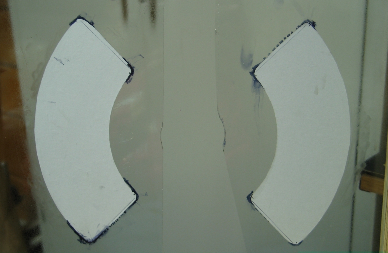
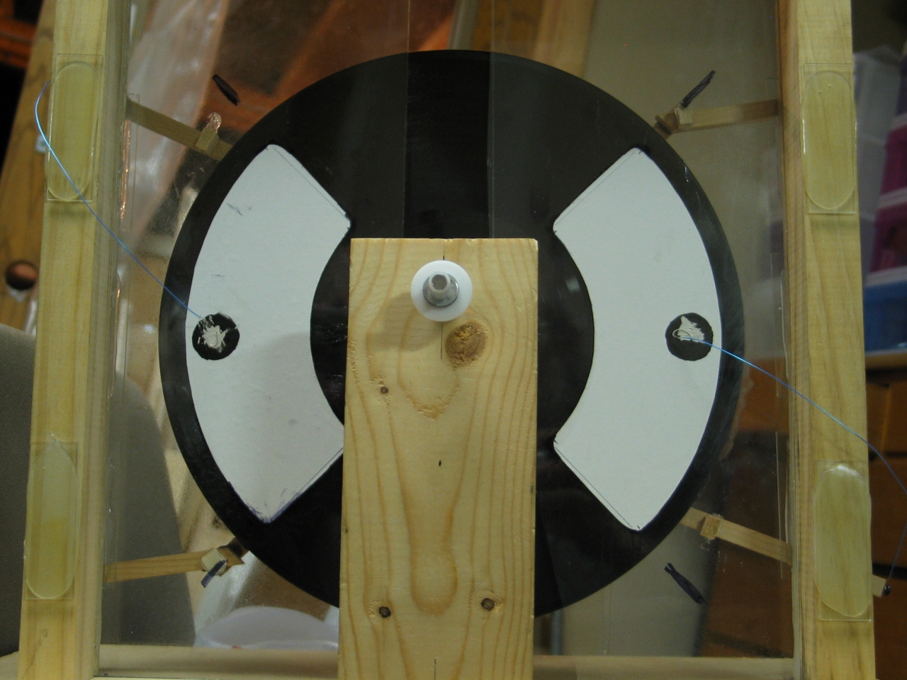
Here are photos of the inductors, in place. The
picture on the left was taken from the front,
and the one on the right was taken from behind.
You can see where I have carved away a small amount
of glass, in the middle, to make a larger space for
the pressure plate on the back of the rotating disk.
(16 July, 2007)
I need to be able to make contact with the foil, but
that side of the paper is stuck to the glass.
Carbon-based ink (Sumi ink or India ink, for example) is
known to be conductive enough to serve as the sector
material, but would it soak through the paper enough to
let me contact the foil? I took a small circle of the
same kind of origami paper the inductors are made from,
and painted Sumi ink on the back. After it dried I
scraped a bit of the anodized surface off the foil side
so I could touch actual metal with the probe of my
meter, and was very happy to discover that the answer is
a clear “Yes.”
Then I thought about the fact that the disk may end up
rotating either way, depending on whether I’m
turning it by hand or with the motor, and that means I
have to be able to swap the positions of the
appropriators and neutralizers. Usually, each
appropriator structure is built at the correct end of
the inductor it’s in front of, and makes contact
there; but (particularly in the case of metal-foil
inductors) there is no earthly reason why it has to be
that way, so I made my Sumi-ink dots at the outer edge
of each inductor, halfway up. We’ll see how well
that works when I get to the point of testing the
machine.
The neutralizer, the collector combs, and the
appropriator brushes all move charge to and from the
disk surface.
The neutralizer is a pair of combs, connected to each
other by a wire or bar, that sweep the disk surface and
remove charge of one sign so that the surface can be
recharged with the opposite sign as it passes in front
of the other inductor. These combs include brushes to
contact the sectors, which hold significant amounts of
charge.
The appropriator brushes, which are connected to the
inductors, must also make physical contact with the
sectors. In order to prevent the appropriators from
being in contact with the disk all the time, the sectors
(or at least small contact points in their middles) are
raised up from the disk. Sometimes metal balls are used
for this purpose, and I may eventually go that route,
but for my first try I am just using metal washers that
are about 1 mm thick. These are wide enough that they
will probably serve as sectors themselves.
This introduces an additional constraint or two; first,
the wobble needs to be smaller than the thickness of the
sectors (or the bosses that protrude from them), as
otherwise the brushes either fail to make contact with
some sectors, or are in contact with other parts of the
disk surface. So far, I do not have any bosses on the
sectors, which are rather thin, so I have to eliminate
as much of the wobble as I possibly can. Second, to
whatever extent the sectors or bosses stand proud of the
surface, parts of the collector and neutralizer combs
must also be positioned sufficiently far above the
surface to avoid collisions.
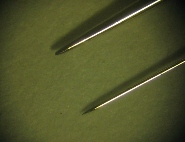
I want to use rather sharp needles in my combs, as that
gives better collection efficiency. Here is a photo
showing an “appliqué sharp” sewing
needle (upper) and an acupuncture needle (lower), viewed
through a low-power microscope:
Usually, only acupuncturists can get acupuncture
needles. I managed to get my hands on one for long
enough to take this photo, but I will be using sewing
needles for the combs on my machine unless I luck out at
a garage sale or something. (I suppose I could sharpen
the sewing needles; but I am going to need about 4
dozen, and I’m not willing to spend the time it
would take unless I am very sure that the results will
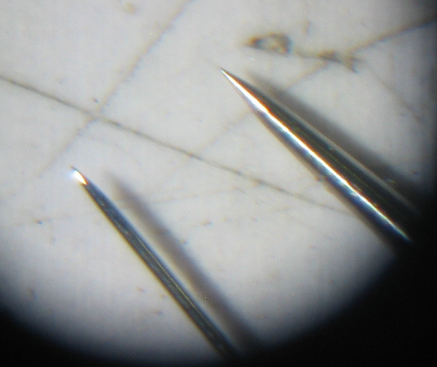
be worth it.) It is definitely possible, btw, to
sharpen one of these things. Here is the same sewing
needle (upper) after I chucked it into the Dremel and
rubbed it on one of my favorite ultrafine abrasives,
compared to the same acupuncture needle (lower) —
(Sorry about the focus.)
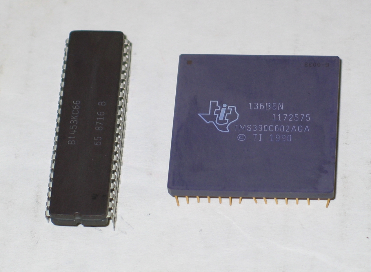
Here’s the abrasive, a brown ceramic integrated
circuit package (left). The purple (right) and white
ones and most gray ones are too coarse for this, though
I do use them for sharpening calligraphic pen nibs,
which I then polish with the brown ones...
To whatever extent I can optimize charge collection it
seems pointless to lose it to corona, and I plan on
surrounding the needles (except, of course, the region
directly in front of them) with a structure intended to
minimize losses. Wood turns out to be a vaguely
semiconducting material, and is very good for equalizing
field contours and thus performing this function. I
expect to build the brushes and combs of this machine
from it, and I will include photographs as I construct
those parts. In the meanwhile, you can find out more
about this use of wood by reading the description of
Winter’s machine at the beginning of Homemade
Lightning, by R. A. Ford.
A typical Voss machine (as on the Kenyon page I link to
above) has 6 sectors, but I am initially using only 4 on
this device, for ease of construction. The sectors are
present partly to get the machine to self-start, and
partly to charge the inductors; the surface of the disk
(at least, the part that is in front of the inductors)
is the primary charge-carrying region. In this regard,
the Voss machine is somewhat like a hybrid between the
Wimshurst (which uses its sectors as charge-carriers)
and the Bonetti (which uses an area of the disk’s
surface as its main charge-carrier, and lacks sectors).
(16 July, 2007)
I don’t really need anything fancy for a first
test, so last night I put a sewing pin under the
microscope, next to the appliqué sharp needle.
To my surprise, I found that the points were quite
similar in size, though the barrel of the pin is
thicker. Clearly, pins will do for a first test, so I
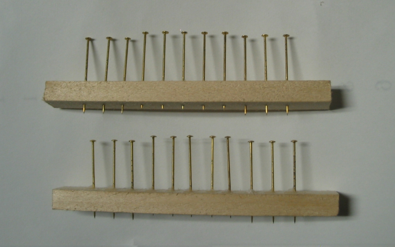
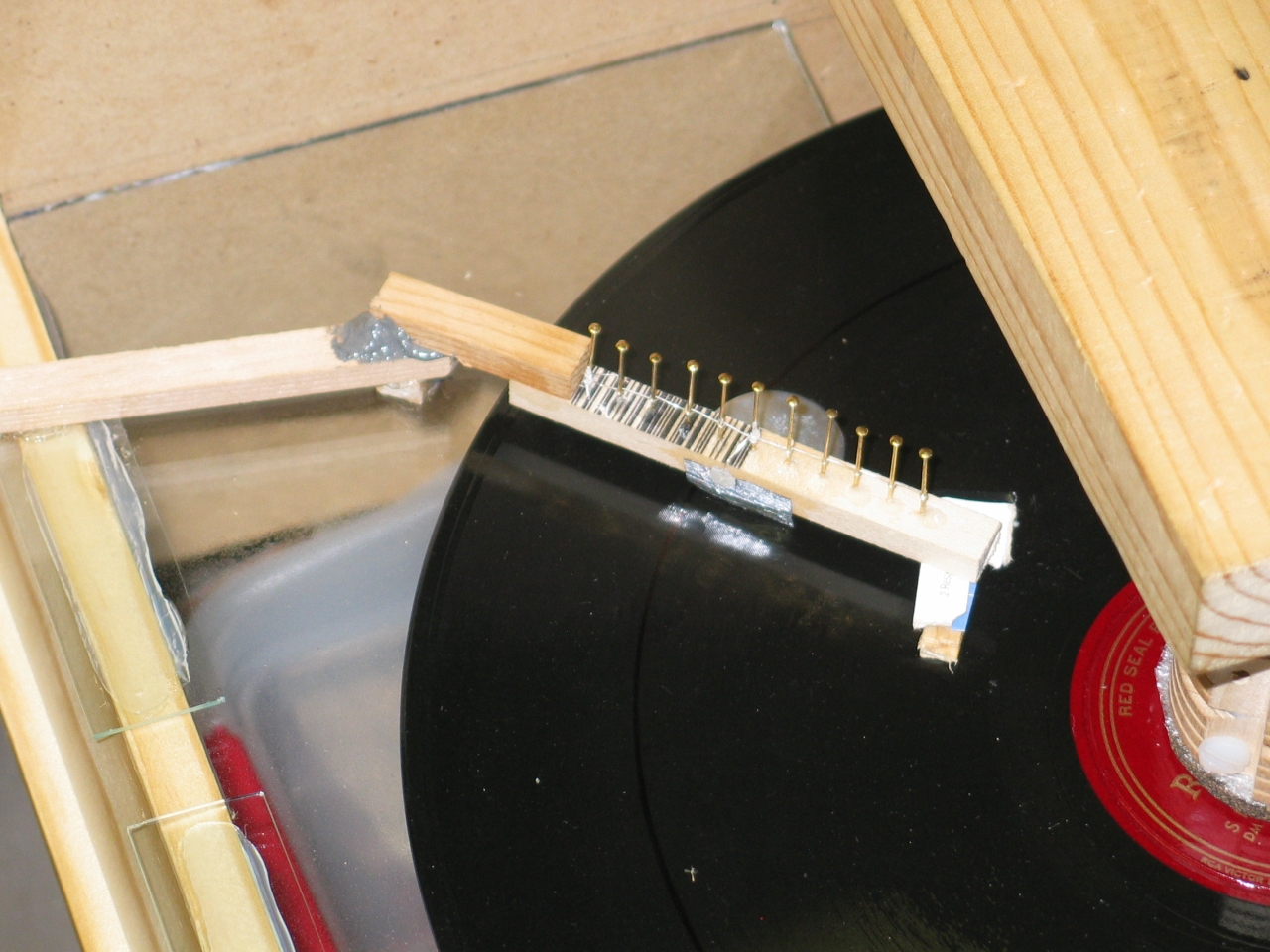
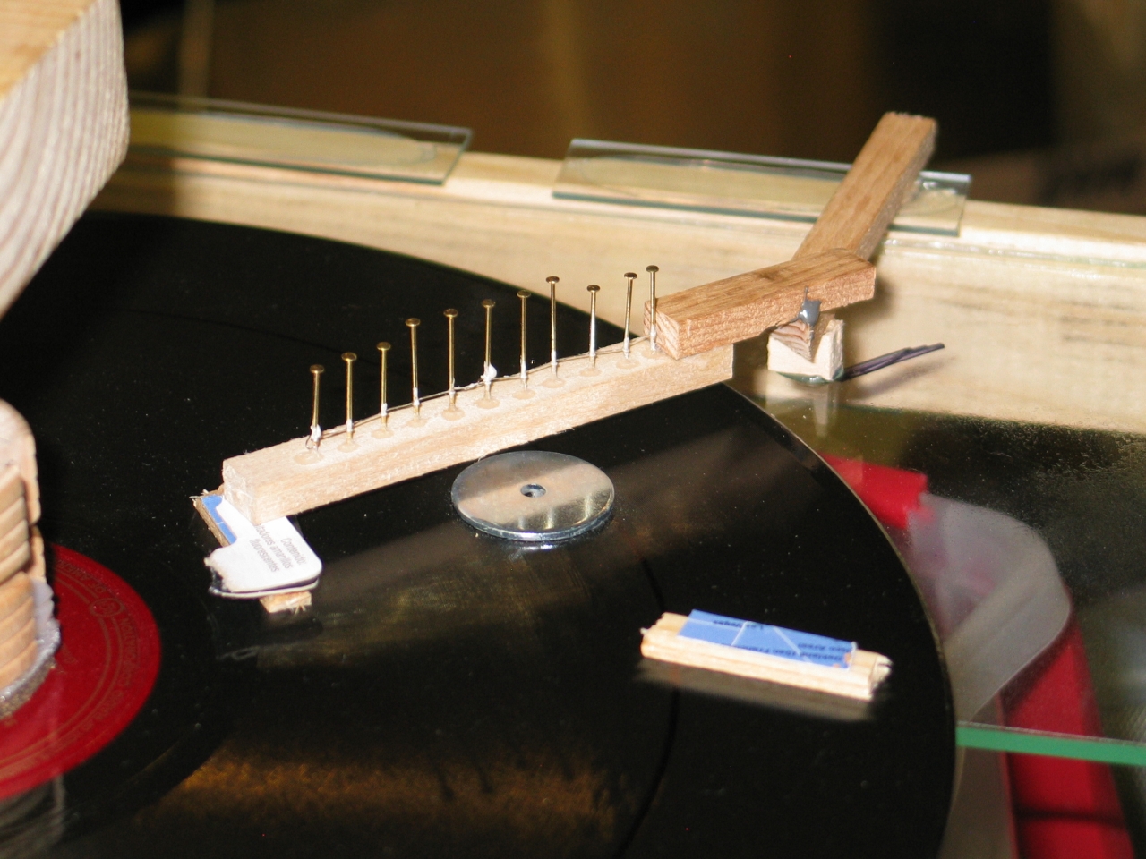
took my Dremel and a #67 drillbit, and made 4 combs.
Here are two of them:
The pins are 1/4" apart, and there is 1/2" of clear
space at each end. There are 11 pins in each comb.
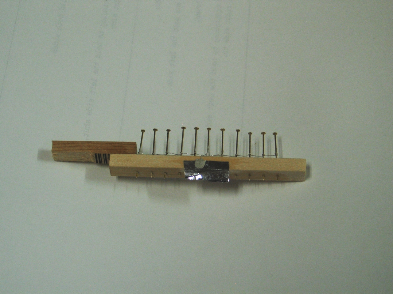
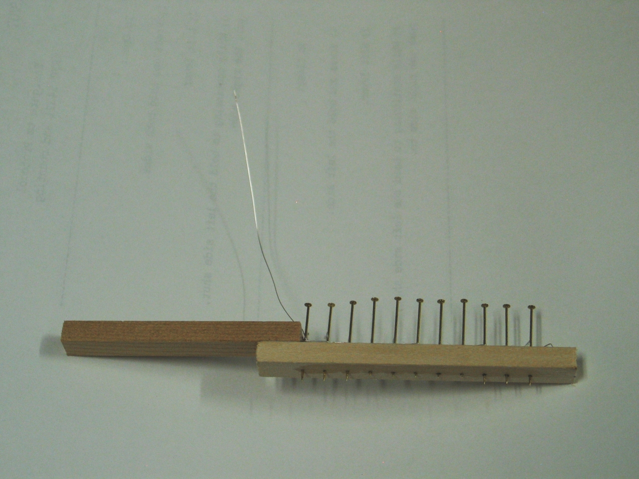
I made these by pushing the pins too far through the
wooden bar and then pressing the bar down onto two
pieces of glass about 3" apart on the bench, with a
washer in the middle of the space between them. (You
will notice that the 5 points in the middle do not stick
out as far as the 3 on each end. This is so they
won’t collide with the sectors if I position the
combs very close to the disk.) Once everything was
positioned nicely, I put a dot of cyanoacrylate glue
around the place where each pin went into the wood. I
will probably just use thin wire to connect to these;
there isn’t really any reason to get fancy about
it at this stage. The “real thing” will be
entirely encased in wood in any case (except for the
points of the needles), and thin wire will work just
fine. The current involved here is measured in
microamperes, after all.
Two of the combs need to have brushes added to them so
they can serve as neutralizers. I am thinking about
using some very thin metallized Mylar™ for this,
as I happen to have a scrap of it here.
If I can figure out how to position these things,
it won’t be long before I make a preliminary
test.
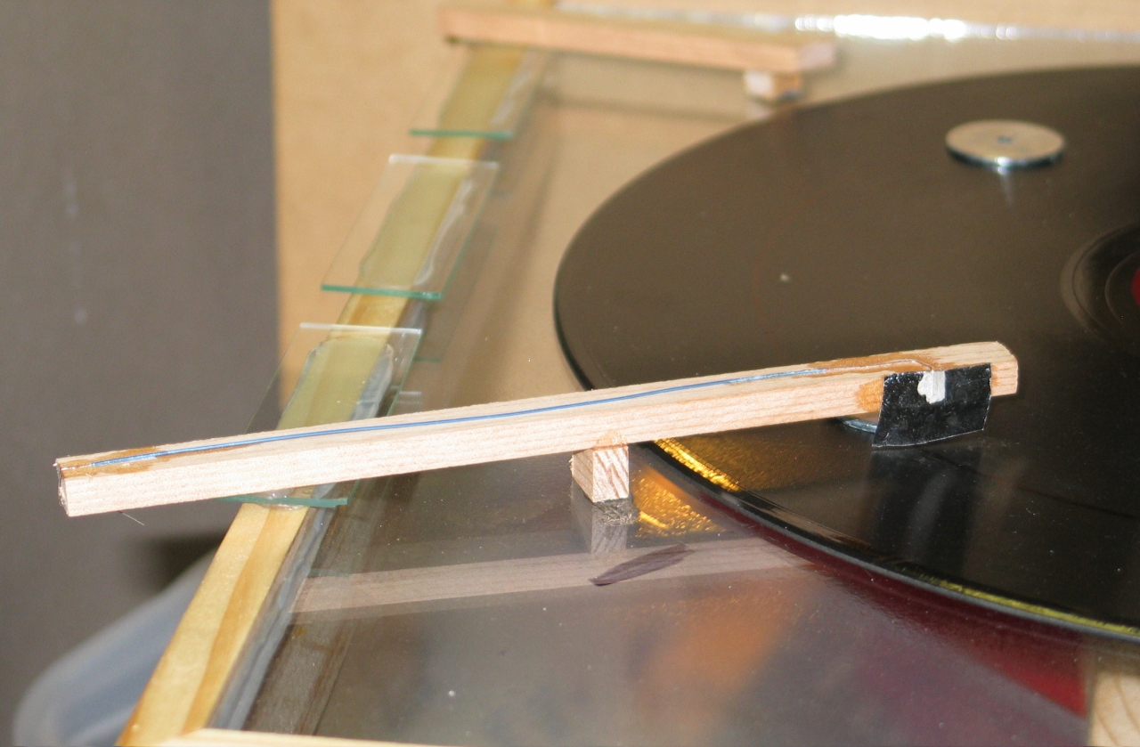
(19 July, 2007)
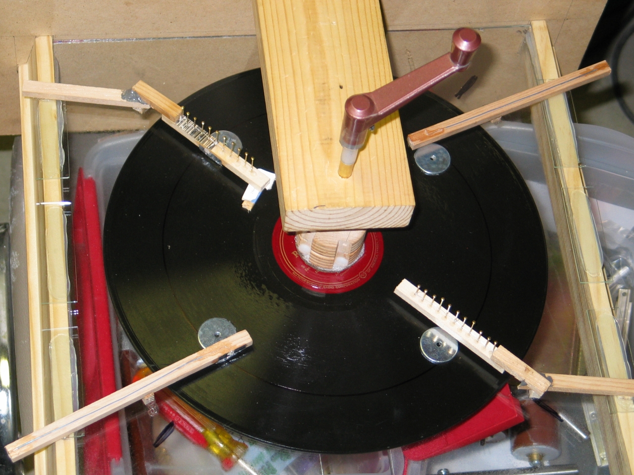
Here are views of some of the bits, as constructed
and in place. The machine is lying on its back,
which accounts for the screwy angle. The handle is
exactly what it looks like (a window crank), but I
have adapted it by gluing a brass tube into it with
J-B Weld epoxy.
(Those last two were taken while the epoxy was
still wet.)
Here are two of the back side, showing the way I am
connecting the inductors to the appropriator brushes:
Note that these are all temporary, for testing.
The wooden bars are stuck to the microscope
slides with RTV, and can easily be removed.
One important thing to remember: this machine is set up
for clockwise rotation of the disk. As the
sectors begin to pass in front of the inductors they
pass under the appropriator brushes, and then as they
begin to move away from the inductors they pass under
the neutralizer brush/combs.
(evening of 19 July, 2007)
I tried running the machine, to no avail. I tried
starting it with a piece of PVC pipe that I had rubbed
with paper, but that didn’t work; I even tried
connecting the appropriators (and thus the inductors)
across the output of the little Wimshurst machine that
I’ve been running my TEA nitrogen laser with.
Still nothing. It behaves as if somewhere, somehow,
charge is leaking fairly rapidly and preventing the
machine from doing what it should. I have already
checked a fragment of another similar disk with the
Wimshurst, and it did not leak, so I doubt that the disk
is the issue, but I will be checking it with the
Wimshurst anyway, to be sure. (I did. It wasn’t.)
(Early morning, 21 July, 2007)
I smell ozone.
Two things (at least) are going on here. First: in the
process of checking the appropriators and inductors, I
discovered that the ink spot on the back of one of the
inductors was not really making decent contact with the
metal foil on the front. I took an X-Acto® knife and
carved a tiny bit of paper away from the foil of the
inductor at the outer edge, near the ink spot. Then I
smeared silver conductive adhesive on the scrape and
over to the ink spot. End of that problem. For
obvious reasons, I then repeated this with the other
inductor.
Second: it turns out that metallized Mylar probably
isn’t the absolute best material to make the
brushes out of. I discovered this by verifying
correct conductivity everywhere else, and then
finally putting one of the meter probes on one
of the sectors, which was in contact with a brush.
Nada. Open circuit.
I ended up putting silver conductive paint on all four
brushes, several times, after which I finally began to
see some charging. I can smell ozone, and if I hold my
finger near the disk while I rotate it, I get tiny
shocks. It’s a Voss machine! Now I have to give it
some output combs and see whether I can get reasonable
performance out of it. (The RTV is setting, and I
should be able to do more testing during the day.)
(some hours later)
Here is a photo of the machine with the collector combs
in place:
(Sorry that’s a bit fuzzy — it was a
longish hand-held exposure.)
With the combs in place, I was (just barely) able to use
the machine to operate a TEA nitrogen laser, which was
the original design intention. I suspect that things
will be easier with “final” brushes and
combs instead of the temporary versions I’m
currently using, and with a motor drive instead of hand
cranking. Things will also be easier when I find a
better material to make the brushes out of. I will
probably be testing some possibilities as my next
step, unless I just decide to build a new machine.
(I have a glass disk that is 4 mm thick and 50 cm
across...)
(04 August, 2007)
Well, I had a disk like that. Turns out that
it was was tempered, so when the glass shop tried to
drill a hole in it, it turned into many tiny pieces.
They are going to make me another one, 20" across,
3/16" thick, and with a 3/4" hole in the middle.
In the meanwhile, I have acquired some acupuncture
needles. These are 0.12mm diameter (as thin as
I’ve seen so far), and impressively sharp.
Here is my specially sharpened “appliqué
sharp” sewing needle, next to one of them:
I am constructing new combs with these needles, to
see whether I can improve the operation of the machine
before I build a larger one. Here are some early stages:
I am planning on covering the tops of the cutoff
needles with another piece of wood, and I hope to
connect to this array with wire that is insulated
for 40 kV.
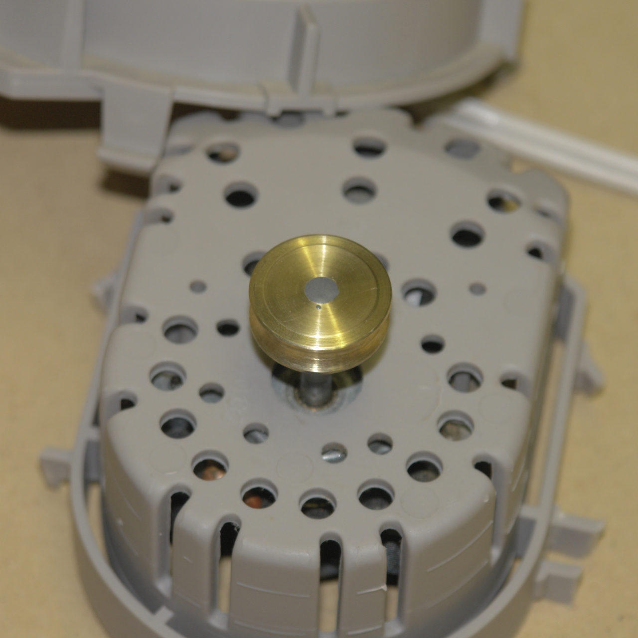
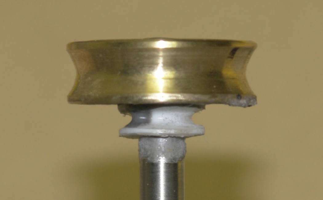
Here are the motor I expect to use, and its pulley:
The motor comes from a small ventilation fan or
humidifier, acquired at a local thrift store. The pulley
is a small one, removed from a little sheave that I got
at the hardware store. I drilled it out so it would fit
onto the motor shaft, and cleaned it up slightly so that
it is fairly well balanced. It is held onto the shaft
with J-B Weld epoxy.
I am still thinking about the shaft pulley on the
machine, and how to attach it. (More about this later,
as it begins to take shape.)
(13 August, 2007)
I have built a new set of brushes and combs for this
machine, using 0.012mm acupuncture needles for the
combs. Brushes and combs are encased in wood. (I will
take photos as time permits.) I tried this setup with a
second phonograph record, and was not satisfied, so I
bought a piece 0.093" Lexan™ (polycarbonate);
marked a 12" circle on it by tracing around a phono
record; cut out the circle with a scroll saw and filed
the edge a bit to smooth it; attached 6 washers for
sectors; and installed it. A Neoprene™ washer
(1/4" hole, 2" diameter) replaces the hard white foam
and cork composition circle that I was using between the
original disks and the collet. The pressure plate for
this disk is the one that I made for the second phono
record; it is cut from a plastic cap that originally
graced a spice jar. (Again, photos later.)
There is no guarantee that this will work well, but I
should note that when I removed the plastic protective
sheet from the front of the disk it took on a nice
static charge, which certainly bodes well. I have not
bothered to remove the sheet from the back of the disk;
I doubt that it makes any real difference. (If I change
my mind later, I will probably be able to remove it
without destroying the setup.) I should note that this
new disk is not flat, and also that it is considerably
more flexible than the phonograph records were. I
don’t think wobble will be a huge issue, but the
center of the disk bulges out (toward the front of the
machine). This may worsen as the disk becomes charged
and is attracted to the inductors... We Shall See.
As I write this, on the evening of August 13th, the RTV
(aquarium caulk, in this case) is still curing. I hope
to be able to test the machine later in the evening, but
it may have to wait until morning. I will report the
results if they are worth reporting.
(14 August, 2007)
While I am having a bit of trouble with the brushes
and the bearings, this unmistakeably works. I ran a
small TEA nitrogen laser with it, as a test. It is
slower than the commercial Wimshurst machine that I
normally use for that purpose, perhaps partly because
it has only one active disk. There may also be issues
with conductivity inside the neutralizers. Either way,
it is obvious that polycarbonate is viable as a disk
material, though it is not as stiff as I’d like.
(08 August, 2007)
In a paper that is available on the Web,
Noël Félici
offers some interesting insights on charge transfer.
Our machines operate in what he calls “Low
Mobility” mode. Under somewhat different
circumstances, it becomes possible to transfer
considerably more charge. Félici was granted
several patents for his work; his machines produced
as much as ~2 W/cm2, with maximum power
outputs ranging as high as kilowatts (!).
I would like to investigate the low end of high
mobility (as it were), and I hope to rebuild this
machine in a way that will permit me to do so.
First, however, I am going to replace the original
disk with another, because something is wrong now
and the machine isn’t working. As long as
I’m doing that I will also be replacing the
brushes and combs with new ones of a different
design, to see whether I get good performance.
Once I’m reasonably satisfied (or the machine
fails again and I conclude that phonograph records
of the type I’m using are poor candidates),
I will begin to think about a glass disk and more
stringent conditions. I will continue to post as
things proceed.
(16 August, 2007)
I bought a sheet of Lexan™ (polycarbonate),
12"x24", 0.093" thick, and made a disk from it.
This clearly works, but I am still having some
trouble with brushes and combs. I conclude that
Litz wire is suboptimal for brushes, as it tends
to be hard to strip (tiny wires with plastic coating,
unless you can get ancient stuff with varnish/lacquer
instead) and not springy enough.
Even so, I have been able to power my little TEA
nitrogen laser with this disk, and I am once again
thinking about motorizing this machine.
The best source of information about the Voss machine
(and other electrostatic machines) on the Web that I am
currently aware of is
a set of pages by Professor Antonio Carlos M. de Queiroz.
There are occasionally issues with the server, so if you
cannot see these pages the first time you try, wait a
while and try again. They are well worth it: there is a
huge amount of information on them and in the links that
Professor de Queiroz provides, and he has built a wide
variety of extremely good electrostatic machines himself.
My email address is a@b.com, where a is my first name
(just jon, only 3 letters, no “h”), and b is joss.
My phone number is +1 240 604 4495.
Last modified: Thu Jun 23 16:04:29 CDT 2016
Sidebar: Construction of the Collet
Sidebar: Why We Love Japanese Saws
The Inductors and their Mounting
Brushes and Combs
Motor Drive System
Continuing Development
Future Directions
the Joss Research Institute
19 Main Street
Laurel MD 20707-4303 USA
Contact Information: