|
by Jacques Charrier
Send email to
Jacques Charrier Preparation Nantes CAPES
|
|
|
|
|
by Jacques Charrier
Send email to
Jacques Charrier Preparation Nantes CAPES
|
|
|
|
|
The animated figure above is a simplified representation of the operation of a Wimshurst machine. The primary principle underlying the operation of this type of generator is that of electrostatic induction or “influence”; the translator has provided a brief explanation of induction at the end of this page, for those who are not already familiar with it.
Two insulating discs (often made of Plexiglas™) turn in opposite directions. Conducting sectors are attached to the outer faces of the discs. For simplicity, only two sectors are represented on each disc in the figure. The sectors drawn with dotted lines are on the rear disc; the sectors in solid lines are on the front disc. Red represents positive charge, cyan represents negative charge, and gray represents a discharged or neutral sector.
Four brushes (these form “X”-shaped item in the middle of the diagram) are connected to each other (and, in this case, to earth/ground). Notice that one pair faces the front disc and the other pair, at about a right angle (though they are usually built so the angle is adjustable), faces the rear disc.
The points of a collector comb facing a positively-charged sector take on a negative charge by induction; micro-discharges from the points then neutralize the charge of the sector. (This is effectively as if the positive charge were being collected by the points.) Likewise, the points of a collector comb facing a negatively-charged sector take on a positive charge by induction, and effectively collect the negative charge from the sector.
The two Leyden jars, the inner conductors of which are connected to the collector combs, store the collected charges. Note that their outer conductors are interconnected and grounded (earthed).
Let’s follow the rotation of a sector on the rear disc (in the usual direction, which for the rear disc is counterclockwise), starting as the sector leaves the upper edge of the collector comb array on the right-hand side. I have indicated the relative positions in increments of 45 degrees, with 0° referring to the comb array on the right (at 3 o’clock) because that is where the description begins; 90° straight up, at 12 o’clock; and 180° referring to the comb array on the left, at 9 o’clock. The rear-disc sectors are drawn with dashed lines, as are the rear-disk neutralizer brushes.
Note: on a real machine, the charge actually acquired by the sector in contact with a brush is always higher than that of the [main] influencing sector because there is additional influence from the adjacent sectors, which are not represented on this simplified machine.
Now let us try rotating the machine in the opposite direction.
To start the machine so that it negatively charges the condenser on the right-hand side (on the advice of F Bossert):
Conversely, to once again cause the machine to charge negatively on the left:
The operation of the machine appears ideal, but a
question still arises: In steady operation, the twin
sector diametrically opposite the one we are watching
(but on the same disk) always carries a charge of the
opposite sign from that of the one we’re
observing. The reverse, however, could equally well
occur: at the outset, the diametrically opposed sector
could have the same charge as the studied one. In that
case, the machine would not take charge. This does not
occur, so the charges must, in general, be opposed. Some
authors justify the appearance of these opposed charges
by suggesting that the rear brushes (for example)
constitute only one insulated driver. On our actual
machine, however, all of the brushes are connected to
each other through the metal frame of the machine. For
more certainty on the potentials, we connected this
frame and the external conductors of the Leyden jars to
earth ground. Our machine functions very well this way.
The initial figure was created with CABRI Géomètre software. This figure, which can also be animated, requires the use of many conditional points. Without the assistance of my colleague Yves Cortial, I would never have managed to build it. The successive images of animation were captured with Paint Shop Pro, and the final animated GIF was assembled with GIF Construction Set.
To download or launch the CABRI file:
![]() wimjc_yc.figcback
or
wimjc_yc_w.figWindows
wimjc_yc.figcback
or
wimjc_yc_w.figWindows
The most complete site about electrostatic machines is that of Professor Antonio Carlos M. de Queiroz, in Brazil.
[Unfortunately, the next three links appear to be dead.]
The machine of Wimshurst of the Virtual Museum of Daniel Giroux
The homepage of Daniel Giroux.
We await a photograph of the Wimshurst machine of Jean Marie Laborde, the person in charge of project IMAG CABRI-GEOMETRICIAN
This page presents a simulation with a virtual machine. It will help you to understand the way the machine operates, but nothing replaces actual experience with a real Wimshurst machine. If you do not own one of them and do not have the opportunity to buy one, you can build it. François BOSSERT, of the Lycée Louis Couffignal, Strasbourg, has built several; he has provided technical information and plans in an article that was published in the Bulletin of the Union of Professors of Physics and Chemistry, Volume 696, July-August-September 1987, p.881, and is also available on the Web:
The Machine of Wimshurst: Principles and Construction (very simple and very economic) by François Bossert [Translator’s note: this mailto may be out of date. If so, use the one given in the text in the above paragraph.]
[The next link appears to be dead, but the following two are okay.]
College Louis Couffignal, Strasbourg
Another article by Jacques Charrier —
Innovation: The machine of VAN DE GRAAFF
[This section was added by the translator.]
If you start with an object that is charged —
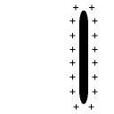
— and you bring close to it a second object, one that can be polarized (for example, something that is electrically conductive), you find that some of the charges in the new object are displaced by the electrical field of the first object (like charges repel one another), so that the side of the new object that faces the original object bears an opposite charge, and the side facing away from the original object bears the same charge:
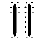
(There is a corresponding movement of charge in the original object, which I will ignore here for convenience.)
If you then remove the charges from the far side of the new object, for example by connecting that side to ground (earth) —
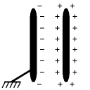
— and you then remove both the connection to ground and the original object, you find that the new object retains a charge, the sign of which is opposite to the charge on the original object:
(I have drawn the two objects the same size and shape here, but that was only for convenience. Likewise, I have drawn the charges the same, also for convenience. The actual strength of the induced charge depends on a number of variables.)
The Wimshurst and other induction machines use various
methods to multiply and collect the induced charge.
Last modified: Tue May 9 13:08:15 EDT 2017