If you want to skip the technical details, click here to jump to the photo section.
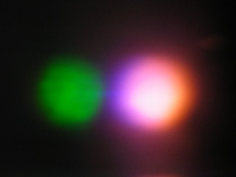
While digital cameras are not overly sensitive to UV, they can certainly pick up some of it, and the results make it difficult to photograph fluorescent specimens with them. When I tried to take a photograph of the green fluorescence of a Calcium Tungstate crystal glaze that I had activated with Erbium Oxide, instead of getting a green spot where the UV from my ultraviolet LED was hitting the tile, I got a bright pink spot.
I was not surprised to find that the blue pixels in my camera were picking up a little of the near-UV, but it came as something of a shock to discover that the red pixels were sensitive around 355 or 360 nm: when I took the same photo through a prism, following a suggestion made by Nancy Lebovitz, I got a green spot, and also blue and red spots that overlapped —
(Notice that the red is actually on the short-wavelength side of the blue. My guess is that either the red filters in the sensor are fluorescent, or that the blue and green filters cut off these particular UV wavelengths but the red filter, for whatever reason, passes them, and the sensor then picks them up.)
Moreover, even filtered Mercury sources, which are extremely common in both shortwave and longwave lamps, emit copiously at the violet edge of the visible spectrum, and cast a “purple haze” (apologies to the late J. Hendrix) across the image. It is necessary to eliminate as much of this as possible, either from the the output of the lamp, or from the input to the camera. (The responsible Hg lines are at 404.66 and 407.78 nm, and possibly the very strong line at 435.8 nm. Hg has other lines in the visible, but they are at longer wavelengths, and are removed by the filter on the UV lamp.)
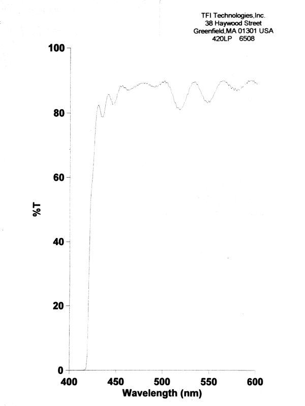
I tried various colored glass filters, all of which failed more or less miserably, and I eventually decided to use a sharp-cutoff longpass filter. I was able to find one with its cutoff centered at 420 nm and with 3% slope, which we purchased from Thin Film Imaging Technologies. I chose the TFITech filter because of its particularly steep slope: most other filters I checked had 6% slope, which would have eliminated more of the indigo and violet than I was comfortable with.
The filter comes mounted in a black-anodized aluminum ring (unless you specify otherwise), and I simply attached it to the front of a regular commercial UV filter (which I use to protect the lens of the camera) with three small dabs of silicone rubber aquarium adhesive. There was some chance that the 48-mm clear aperture wouldn’t be quite wide enough, but I haven’t noticed any vignetting problems.
Here is the measured performance curve of the filter:
(Click any of the small photos to get one that is 800x600 pixels. In most cases, if you want something even larger you can change the “.8c.” in the filename of the large image to “.22c.” for the full-size originals, 2272x1704; but some of the photos are crops, which I’ve tried to note, and are not available at “.22c.” size. Please note that the full-size images are about 1.5-2 MB each, and will take a while to download.)
Here are some photos, mostly with filtered Mercury lamps as the UV sources, primarily an ancient “Mineralight” SL-2537 for short-wave and a somewhat more recent UV Products BL 100 AP for long-wave. (I’ve noted one or two exceptions.)
I must apologize for occasional bright-blue specks: because
modern papers and fabrics are very often brightened with
strongly fluorescent dyes, lint from them shows up regrettably
well under black light. (They’re much less noticeable under
short-wave UV.)
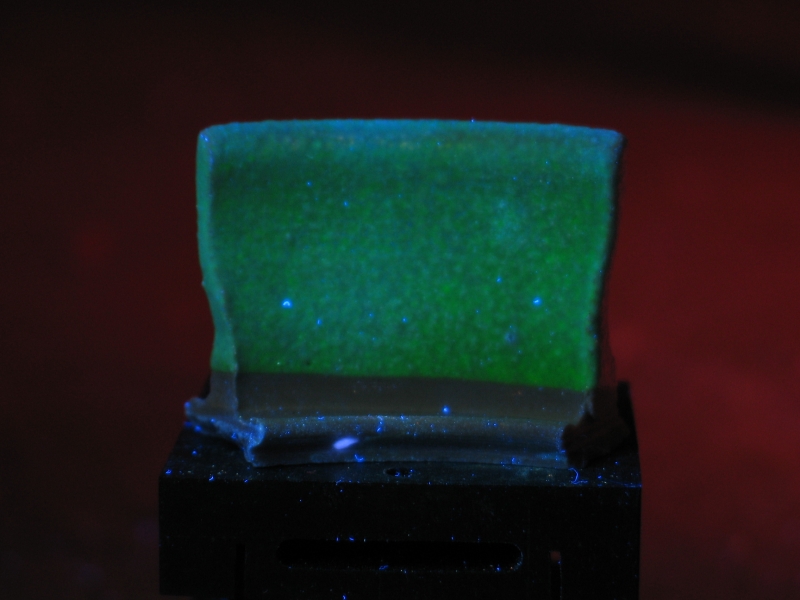
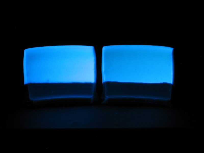
My original purpose was to photograph fluorescent glazes and porcelains, so I will present this section first. The first two pairs of photographs demonstrate the function of the filter.
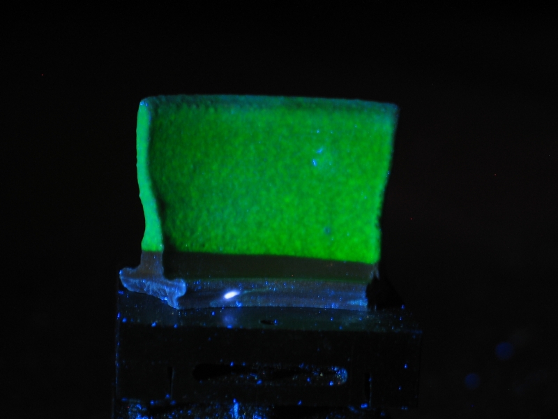
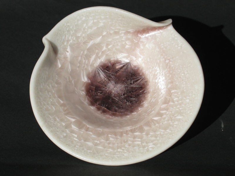
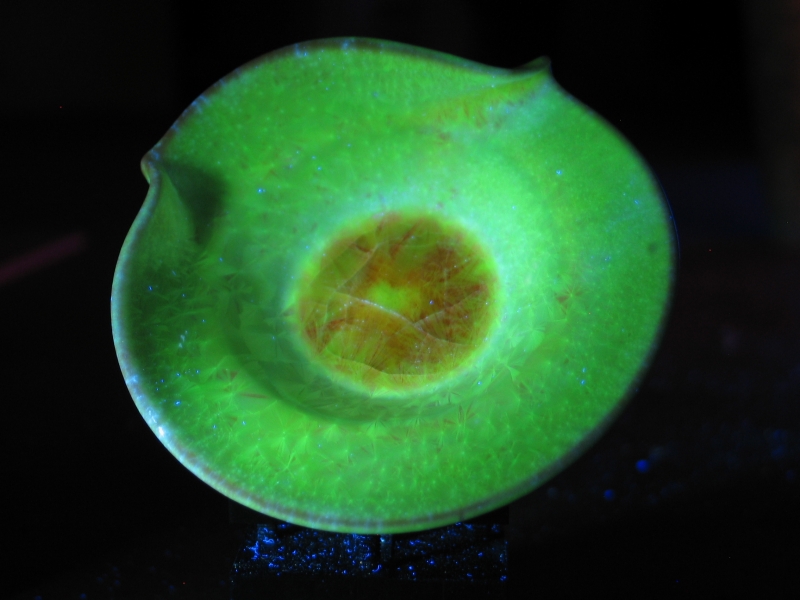
This is a Scheelite glaze that is activated with Er2O3. (Scheelite is Calcium Tungstate, CaWO4; it has a bright blue fluorescence under short-wave UV but is inert under long-wave UV. I formulated this glaze to precipitate small crystals of CaWO4, which is not difficult to do.) I had hoped that the glaze would display the green fluorescence of Erbium, and in fact it does so pretty well.
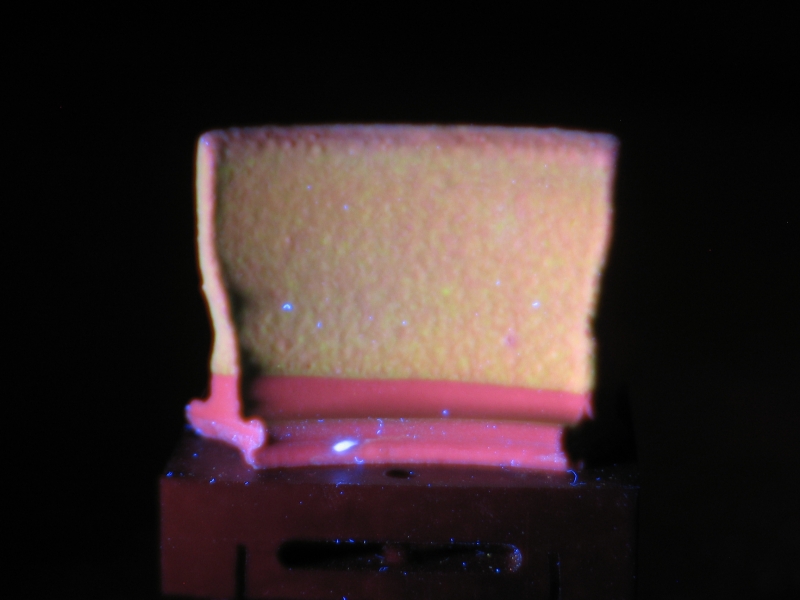
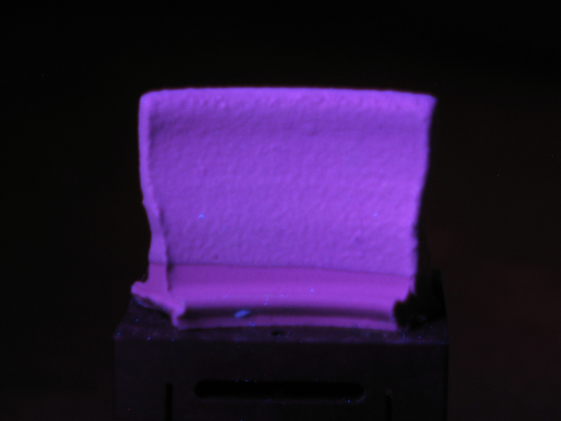
On the right is a photograph of the same tile, taken without the special filter, to give you a sense of how difficult it is to photograph these things if you don’t have the right equipment.
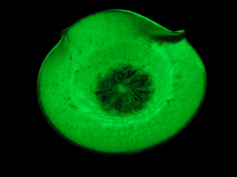
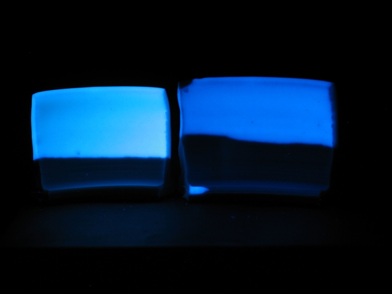
Here are two more photos, showing the same test tile illuminated by a UVL-56 handheld lamp, also from UV Products, which almost certainly emits a spectrum that is slightly different from that of the BL 100. It is also a lower-power device, so these are not as bright, and they required a significantly longer exposure. Again, the photo on the left was taken with the filter in place; the one on the right was taken without it.
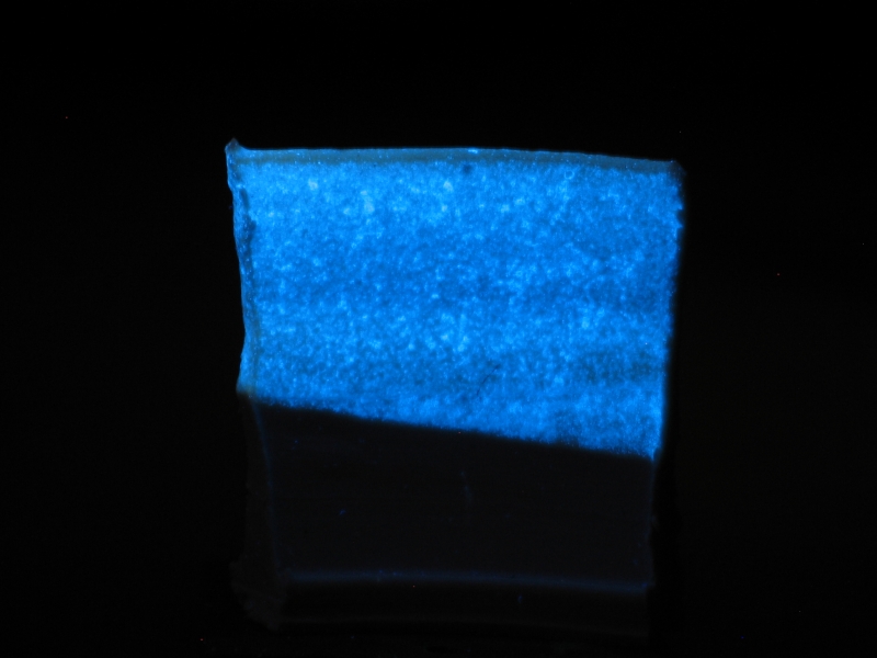
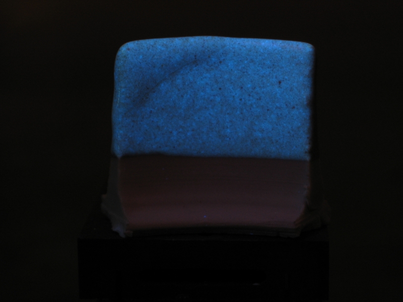
Under short-wave illumination only a little of the green shows up, and the color is primarily due to the fluorescence of the Scheelite crystals in the glaze. To show you what that looks like, here is a plain Scheelite glaze, without any additions, under short-wave UV:
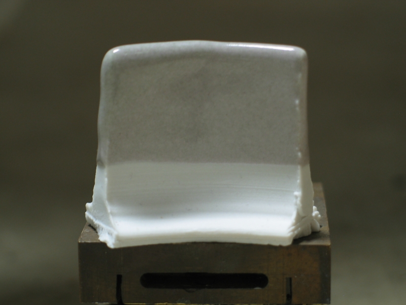
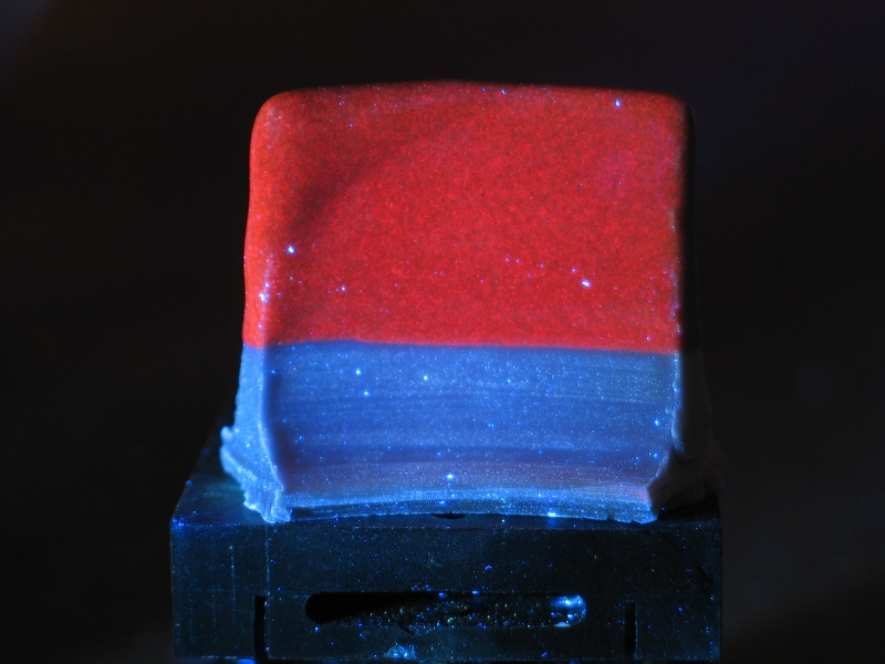
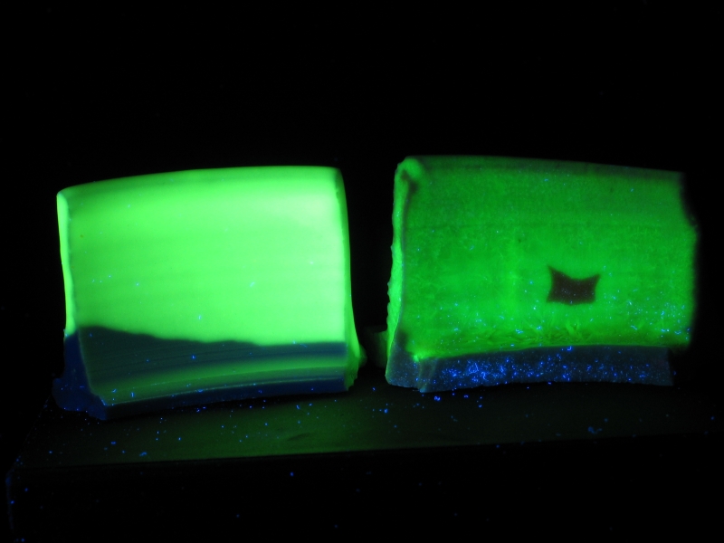
Here is a different CaWO4 glaze, this one with 10% of Ruby Dust added to it. As you can see, the fluorescence is considerably different with different excitation wavelengths. (I am not entirely sure why the glaze is gray in roomlight, but it appears to be a feature of this particular batch of Ruby: it’s the same color when I add it to my regular clear glaze.) As usual, from left to right we have the test tile under roomlight, black light, and short-wave UV.
Here are the photos from my article in Clay Times, in case you want a bit more detail about them. I’ve also included some photos that were either too late to get in, or didn’t fit.
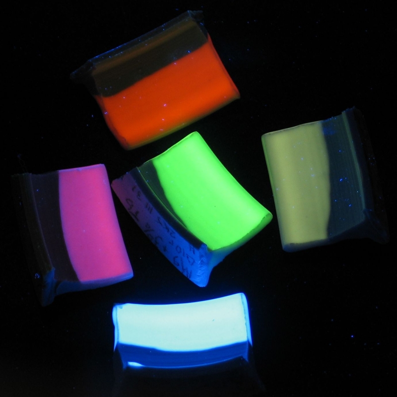
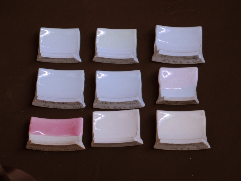
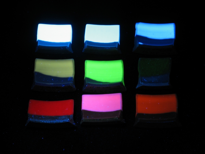
This first photo shows five test tiles that I’ve glazed with my regular Δ 9-11 “M9” clear (the recipe for which is in the article). Each test contains 3% of a “rare earth” oxide. The illumination is black light. Clockwise from top: Samarium, Dysprosium, Cerium, Europium; the green in the center is from Terbium. The Sm and Eu tiles were fired in oxidation; the others, in reduction. (This photo includes the orange, green, and blue tiles that were shown next to each other in a different photo in the article, so I’m omitting that one.)
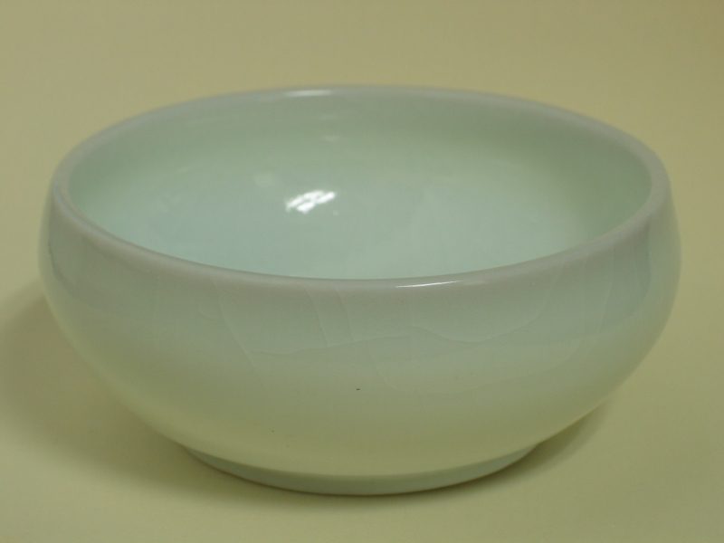
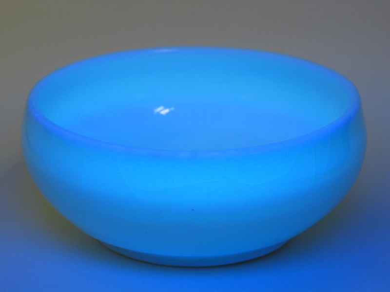
Here is a fluorescent porcelain bowl, about 3 inches across. This is my own translucent porcelain, to which I have added Europium, fired in reduction. (Collection of Nick Younes.) The caption in the magazine is slightly incorrect: the porcelain itself is fluorescent; the glaze is a plain clear, which has picked up a little bit of the Eu from the body. Also, the photo on the right was taken in roomlight plus black light, not just black light.
Here’s an overview in ordinary light, and a view of the fluorescence under black light. Note that the tiles in the top two rows were fired in reduction, and the ones in the bottom row were fired in oxidation.
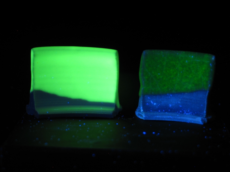
Next photo: Samarium (fired in oxidation) on the left, Dysprosium (fired in reduction) on the right. Second photo: Terbium (fired in reduction) on the left, “Pink Snow” (recipe in the article) on the right. While the Erbium fluorescence in “Pink Snow” is not as bright as the typical Terbium fluorescence, it is a very nice clear green.
(Demontration of Quenching.) First photo, daylight; second photo, black light. The tile on the left has 1% Eu2O3 added to it; the tile on the right has 3%, and is, somewhat surprisingly, not as bright. It also shows slightly more greenish color in daylight. (Please note: “.19c.” is the largest available size of the daylight photo.)

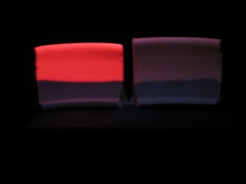
Europium and Cerium: color difference. (1% Eu on the left, 3% Ce on the right.)
Terbium and Willemite: color difference. (3% Tb in a clear glaze on the left, 2% Mn [as carbonate] in a crystal glaze on the right.) My apologies for the lint on the crystal tile.
Ruby Dust in a clear glaze on the left, 3% Eu2O3 on the right. Both tiles were fired in oxidation.
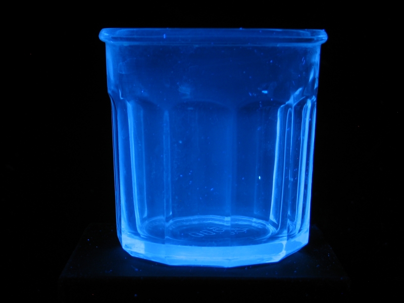
File this one under “Rare-Earth Fluorescences in Everyday Life” — this is a 500-ml jelly jar, under black light. In ordinary light it’s just a clear jar, but there’s some Cerium in it (probably intended as a decolorizer), so it fluoresces:
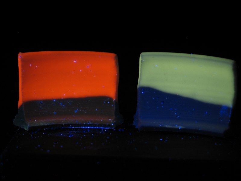
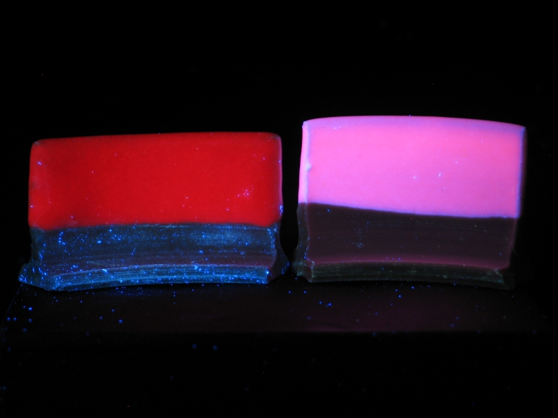
On the left in both photos is Europium, on the right Samarium. The photo on the left shows them under black light, and the photo on the right shows them under short-wave UV.
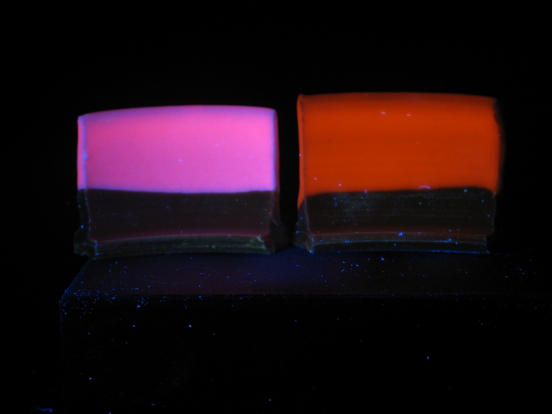
Note that some of the Eu seems to have dissociated, even
in an oxidized firing, so that under black light the tile
on the left is more or less magenta or “hot pink”, a
mixture of red and blue emissions. Eu(II), which is
responsible for the blue part of the color, doesn’t respond
much to short-wave excitation, so only the orangy-red of
Eu(III) shows up in the photo on the right. (Sm(III) doesn’t
appear to be particularly responsive to short-wave UV either,
and that tile is quite dim.)
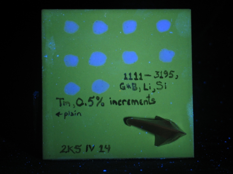
Here is a china paint test, in which I added Thulium Oxide
in approximately half-percent increments to a base that
consists of equal parts Ferro Frit 3195, Gillespie Borate,
Lithium Carbonate, and Silica. There is a stripe of the
plain uncolored base down the left edge of the tile. It is
clear that a percent or so of Tm is about all that is
required for reasonable fluorescence, which is a good thing:
Thulium Oxide retails for about $10 a gram in small
quantities.
The peculiar shape in the bottom right corner is a
self-supportingΔ 016, slightly overfired, being viewed
from above — I glued the cone to the tile with a dab of
china paint and fired the tile flat on its back, so that
I’d have a record of the firing conditions.
Note the fluorescence of the pre-existing glaze on the
commercial tile I used as a substrate. If it were important
to eliminate it, I’d probably make up a nonfluorescent
slip and fire it onto the tile before applying the china
paint; but for my purpose here, an informal test of Tm, it
was not an issue.
It does, however, illustrate the fact that fluorescence
can be used in some cases as a diagnostic or analytical
tool. Tiles made by different factories have slightly
different fluorescences; if a tile is already mounted
and the back cannot be examined, or if only a chip is
available, the fluorescence could conceivably help
identify the source.
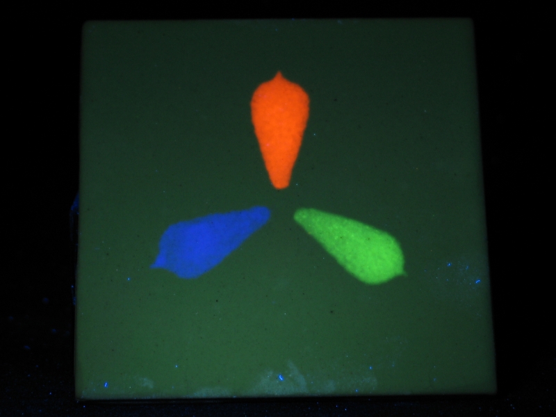
Here is another china paint test, this one a demonstration
of “secret writing”. (Clockwise from the top: Sm
plus Eu; Tb; Tm. I used about 1% of each colorant, so there
is roughly 2% colorant in the orange vertical shape and about
1% in each of the others. The paint is the same “1111”
base as in the test tile shown above. This tile, like the other,
was fired (several times) to Δ 016.) It isn’t quite right
yet — the fluorescent regions are faintly visible in
roomlight — but it will serve as a demonstration of the
general principle.
(Note, added later)
I have also managed to use “Glow Powders”
in china paint base, which results in phosphorescent or
“Glow-in-the-Dark” paint. This is easier to
deal with than the cone 08 glazes that were described in
Ceramics Monthly
a while ago, but those were intended as actual glazes,
not as enamels or paints. Depending on the color, you
may be able to use any of several types of paint base;
I suspect that the less reactive the base is, the better
the resulting brightness will be — you do not want
to dissolve the phosphorescent material.
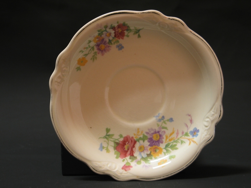
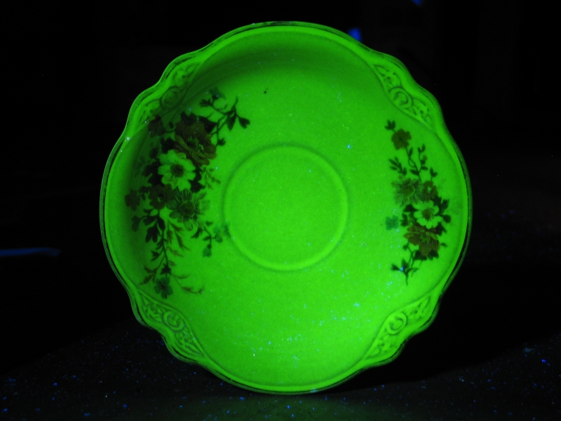
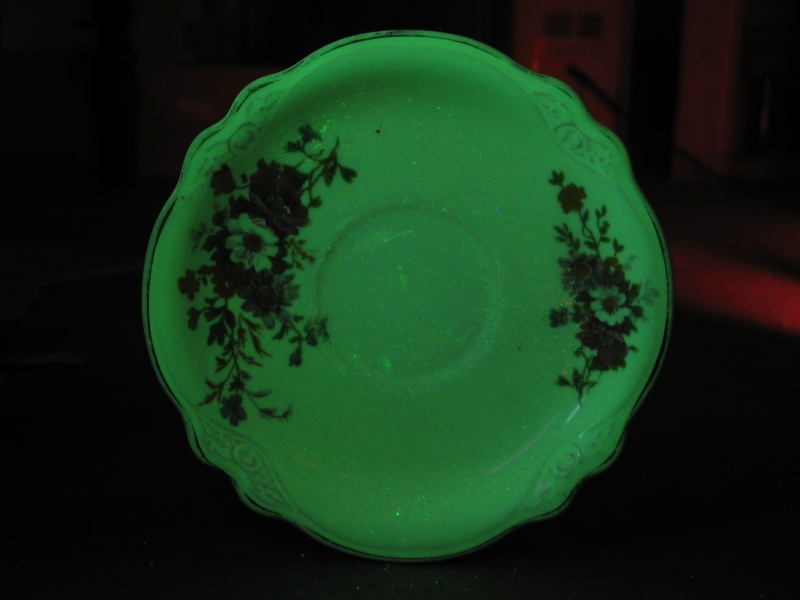
Here’s an odd one. As you can see in the first image,
this is a rather ordinary Homer Laughlin saucer, in their
“Virginia Rose” pattern. I do not yet know why
it is fluorescent; the color resembles that of the Willemite
fluorescence, but it is less pronounced under short-wave UV
than I’d have expected, and I don’t actually
observe any crystals — the glaze, though crazed, is
entirely vitreous. It also resembles the fluorescence of
glasses that contain Uranium Oxide, but the roomlight color
is not as distinct a yellow as I’d expect. (When I get
a chance I’ll take a counter to it and see whether it
emits any alpha. If it is Uranium, there isn’t very
much of it present here, and the activity will be minimal;
still, it may be detectable.)
[NOTE, added 2008 June 25: I just put this saucer
in front of an alpha/beta counter, and although it does
emit, it is only about 10X the background level that I
see here; this strongly suggests Uranium, which is not
very active.]
Again, this points toward the use of fluorescence as an
analytical technique: without the use of UV it is not at
all obvious that there is anything unusual about the glaze
on this saucer, and there is no reason to think about
taking a counter to it.
As usual, roomlight, long-wave, short-wave. I had to use a
4-second exposure for the short-wave image, also fairly
typical: that lamp is of relatively low power.
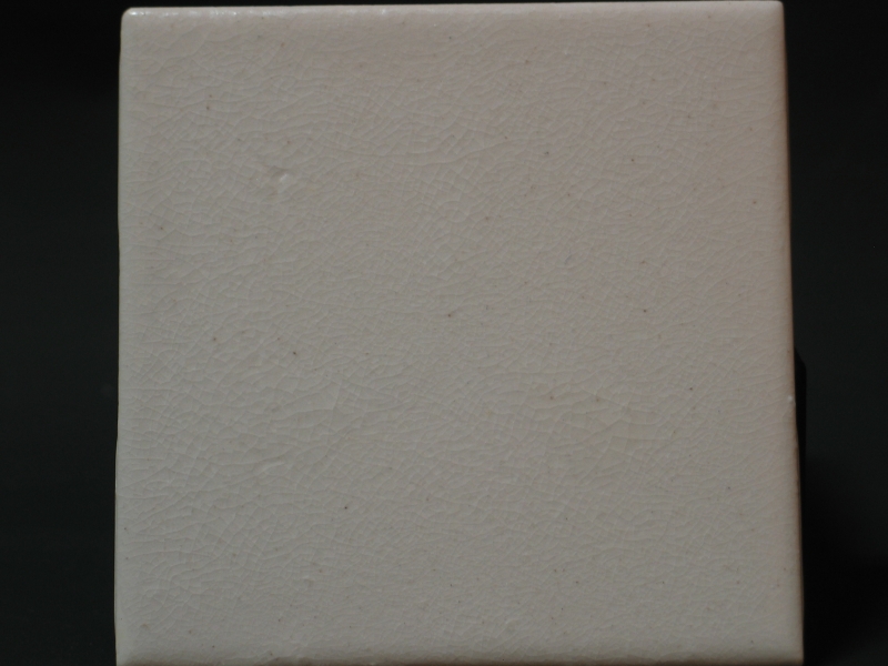
Finally, here’s an ordinary Δ 9-10 crackle clear,
first under roomlight and then under short-wave UV. Many (if
not most) ceramics have at least some fluorescence, and the
color is often different under different wavelengths. This
particular glaze is more interesting under short-wave than
under black light.
From here, we move on to photos that are more or less unrelated
to the article.
This is a fluorite, from Illinois. Photos, from left to right:
roomlight, long-wave, short-wave.
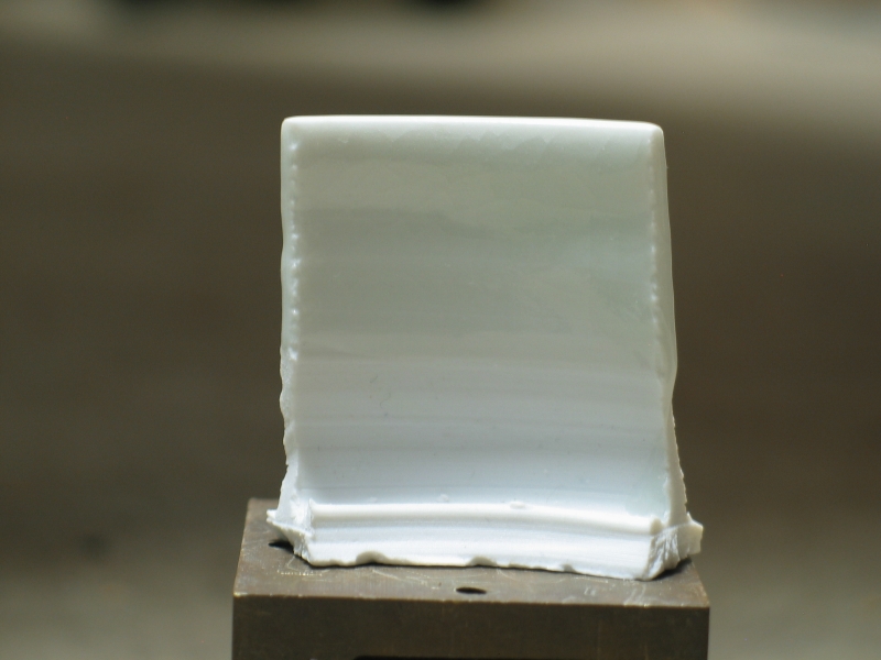
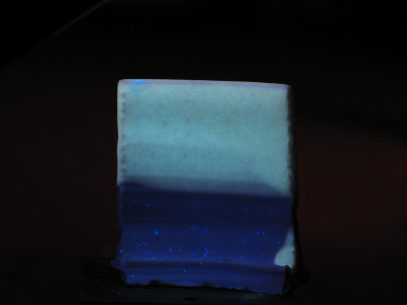
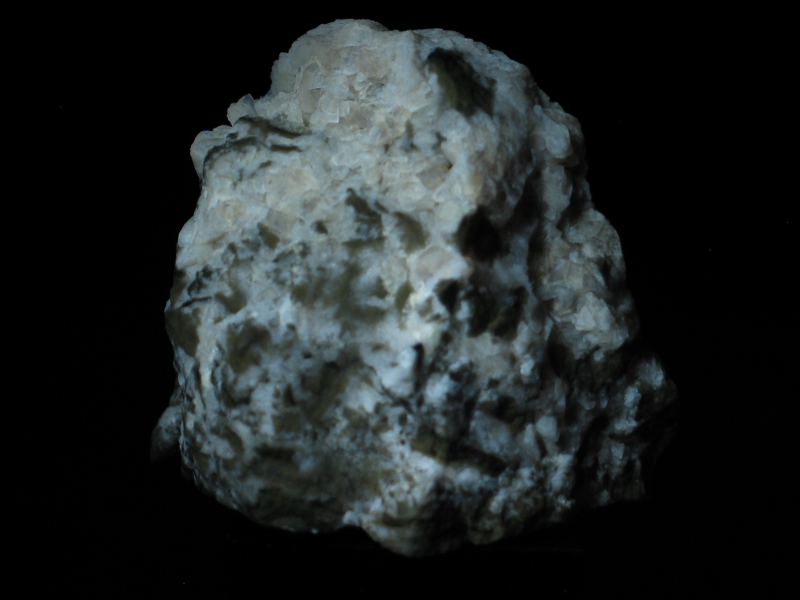
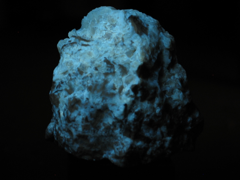
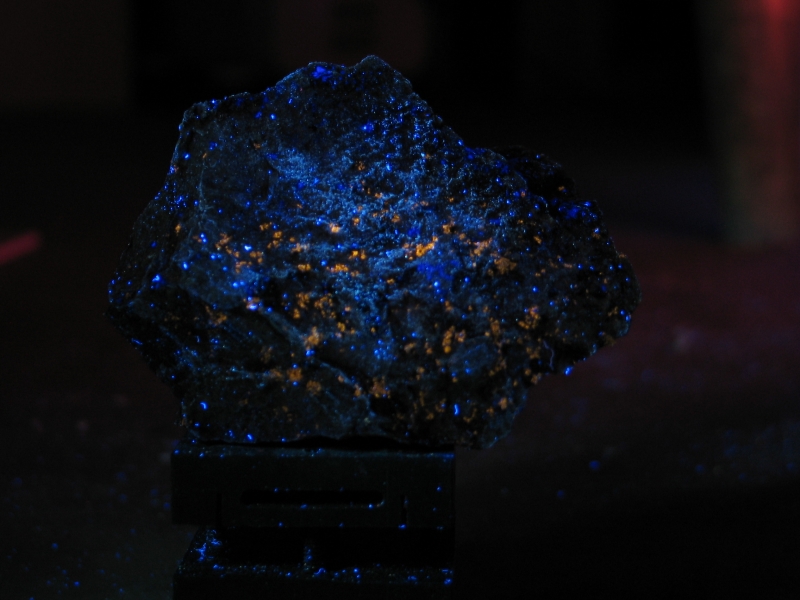
Next, a difficult mineral: some regions of this specimen
fluoresce in the deep blue, and it would probably be better
if I could remove all of the visible emission from the lamp
instead of filtering the camera, because the filter on the
camera pushes the color slightly to longer wavelengths.
Zircon and Feldspar, from Wisconsin; roomlight on the left,
long-wave UV on the right.
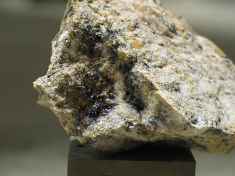
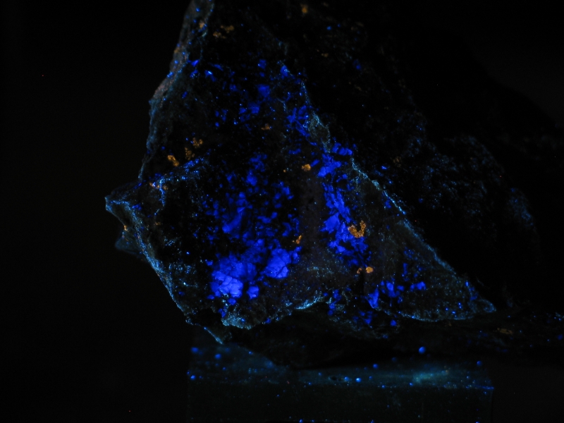
Here’s a different face of the same specimen, first under long-wave
illumination, then short-wave. Please ignore the background, which
is visible in both, but is particularly evident in the shortwave
image.
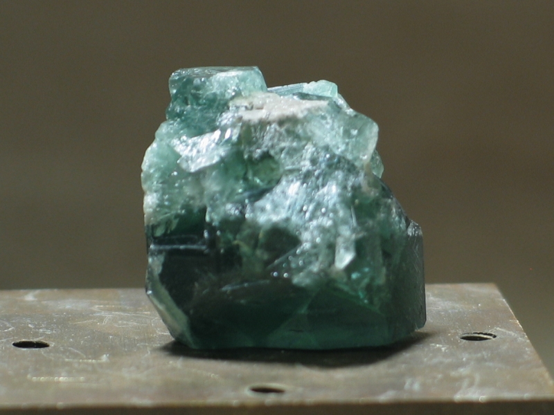
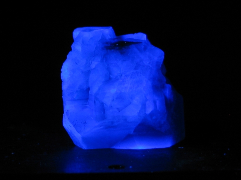
Here’s a really nice specimen of fluorite from Rogerley,
England. These are crops, and “.11c.” is the largest
available size. Again, roomlight, long-wave, short-wave.
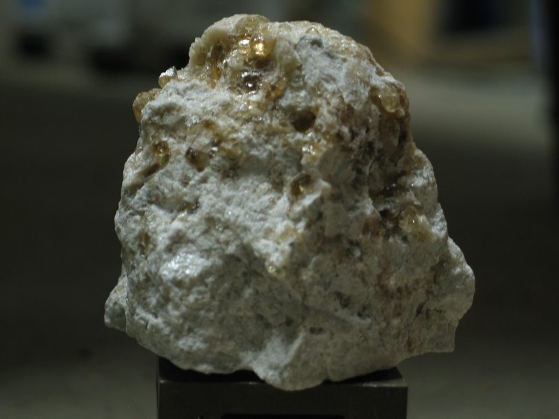
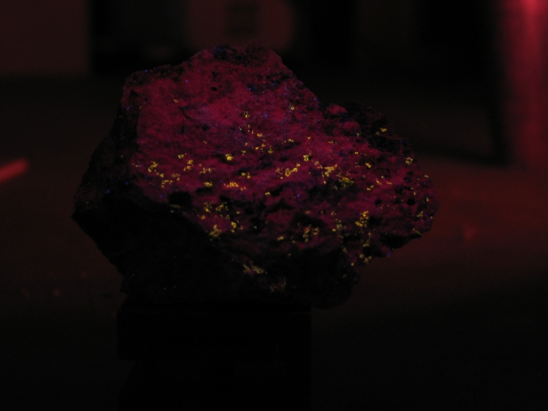
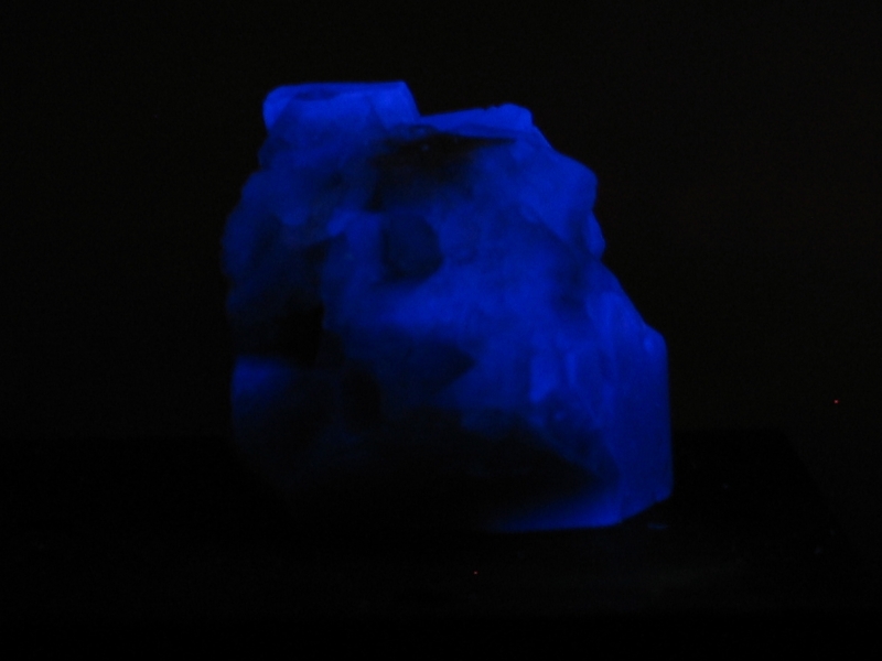
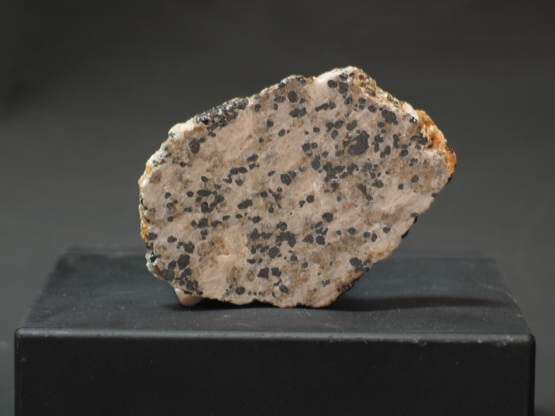
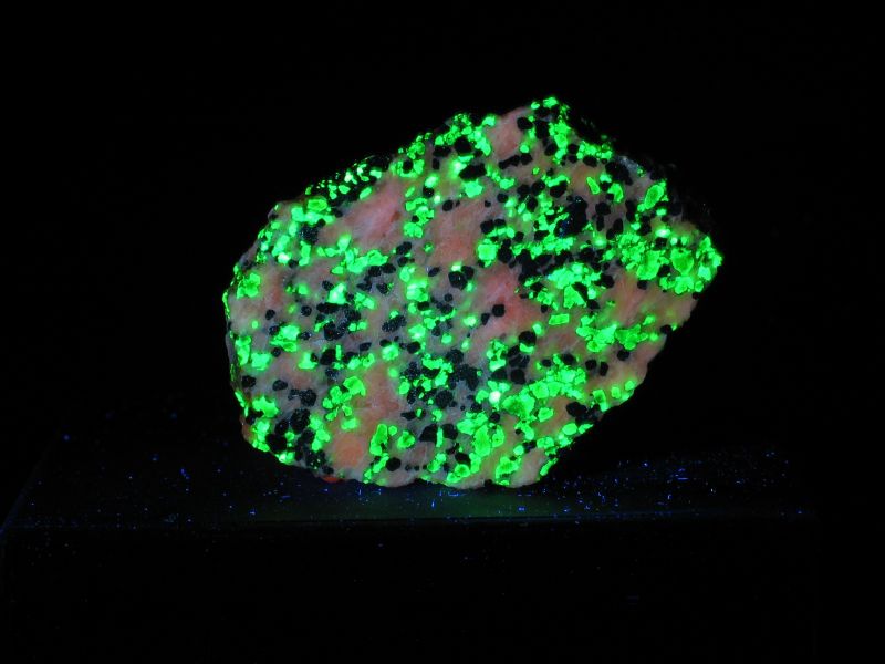
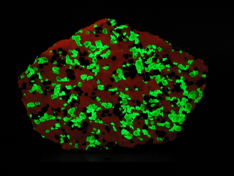
This is a specimen from Franklin, NJ. It appears to contain
Willemite and Calcite; there may be small amounts of other
fluorescent minerals as well. Photos, from left to right:
roomlight, long-wave, short-wave. (The short-wave image was
taken earlier than the other two, and shows the piece in a
different orientation.)
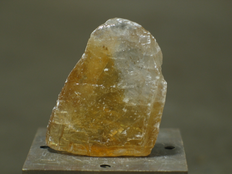
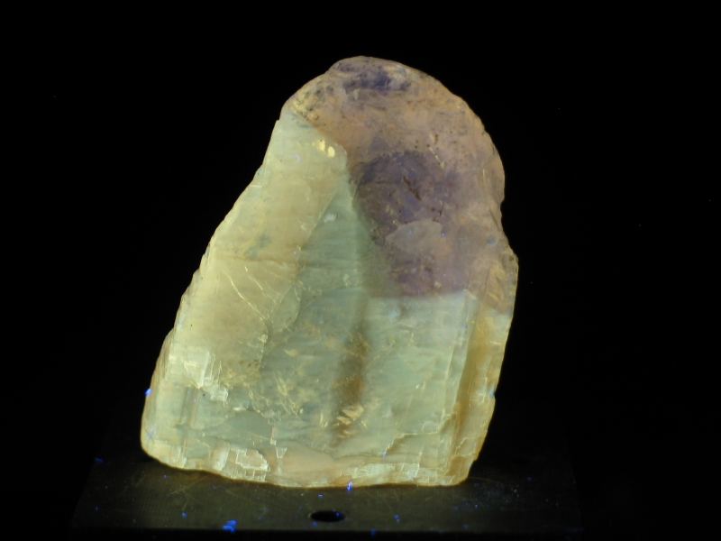
I believe that this is Calcite. Photos, from left to right:
roomlight, long-wave. (I saw very little fluorescence with the
short-wave lamp, and it looked essentially the same as the
long-wave fluorescence.)
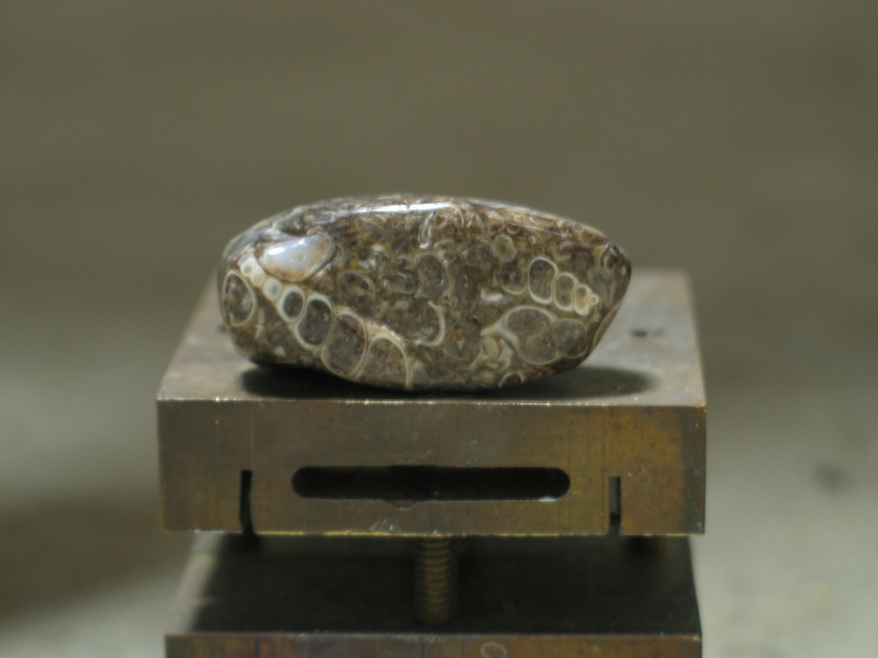
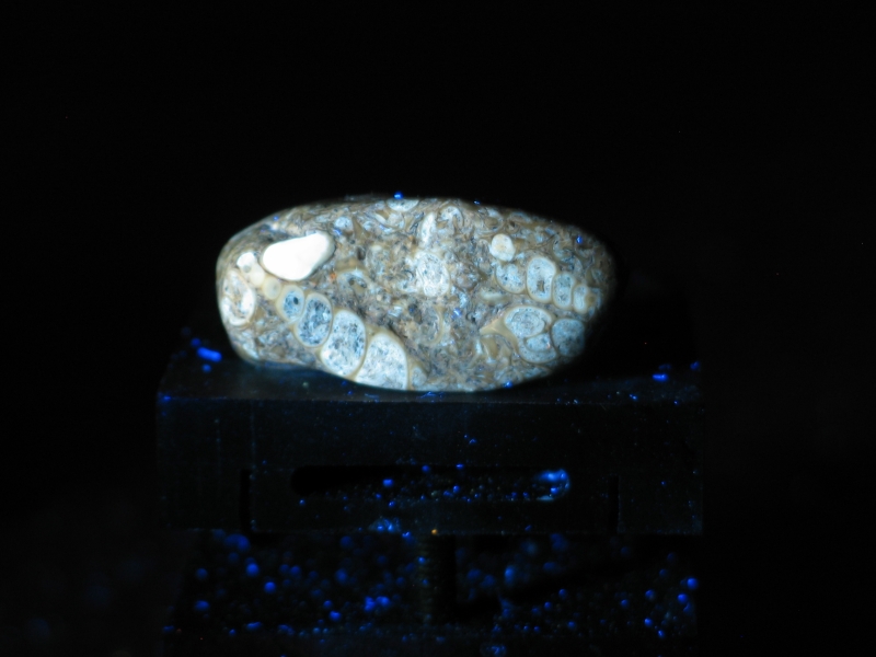
Here is a conglomerate (I think that’s the correct term)
with little fossils in it. My apologies for the dust, which
is mostly visible in the black light photo.
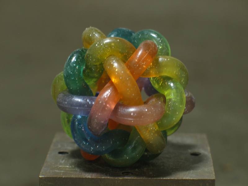
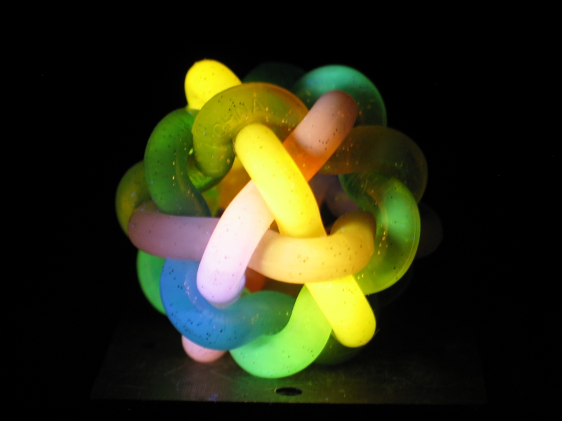
This is a “Mini Orbit Ball”, purchased at
GrandRabbit’s Toy Shoppe,
which is in Boulder, Colorado. As usual, roomlight on the left
and long-wave on the right. (I didn’t see much under short-wave.)
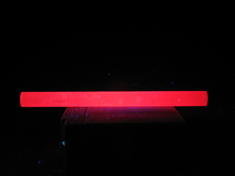
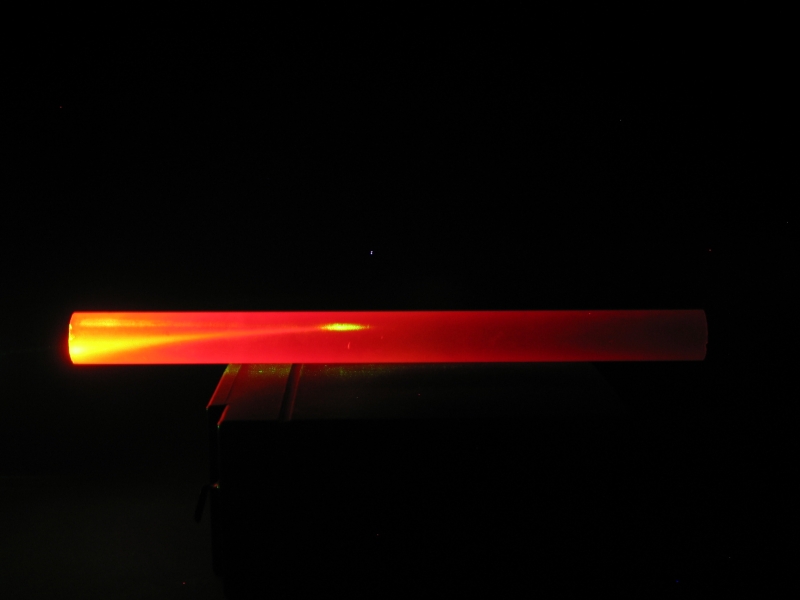
This is about a quarter of a pound of ruby, originally intended
as a laser rod. (Somebody did a bad thing to it, and it was let
go as surplus.) The first photo shows it under black light; for
the second, I shined a green laser pointer into it. This shows
you that red plus green gives the same visual appearance as
yellow, depending of course on how you mix them and how much
of each color is present.
Even with the one caveat about violet and deep blue fluorescences
this is vastly better than I have ever been able to do before,
with film or digital camera, and I am extremely pleased. The use of
the TFITech 420LP filter is clearly a viable method for photographing
fluorescent specimens under either short- or long-wave excitation,
provided that the source is adequately filtered to reduce its
visible output to a minimum. This filter costs $165 at 50 mm diameter,
and although that appears to be somewhat expensive, the performance
cannot be denied. Moreover, it will be difficult to duplicate with
any other filter that I’ve been able to find.
I did look into
the Baader UV/IR blocking filter,
which is also available in 50 mm diameter; but I note (see the upper
curve on the Baader page) that it passes some UV near 355 nm, exactly
where I expect to have trouble with the red pixels in my camera. This
filter is less expensive than the TFITech filter, but the fact that
it requires another filter to compensate for the UV passband increases
both the complexity and the expense. Nonetheless, it may be a viable
alternative if you can find the other filter at a reasonable price,
or if your camera is not sensitive to 355-nm UV.
If your funding is unlimited, you may want to look into the
possibility of using a large shortpass filter with cutoff at
380 or 385 nm on your lamp. This would probably allow you to
use a longpass filter with cutoff at 395 or 400 nm on the camera,
and thus permit you to record fluorescences essentially all
the way to the edge of the visible range. Unfortunately, such
a shortpass filter would be a special-order item, would probably
need to be quite large (depending on the size of your lamp), and
is certain to command a very high price.
My email address is a@b.com, where a is jon and b=joss.
Phone: +1 240 604 4495.
Last modified: Thu Jun 13 23:54:46 EDT 2013
Mineral Specimens
“Other”
Conclusion
The Joss Research Institute
19 Main St.
Laurel MD 20707-4303 USA
Contact Information: