(24 May, 2004 ff, with some additions in 2010 and 2011...)
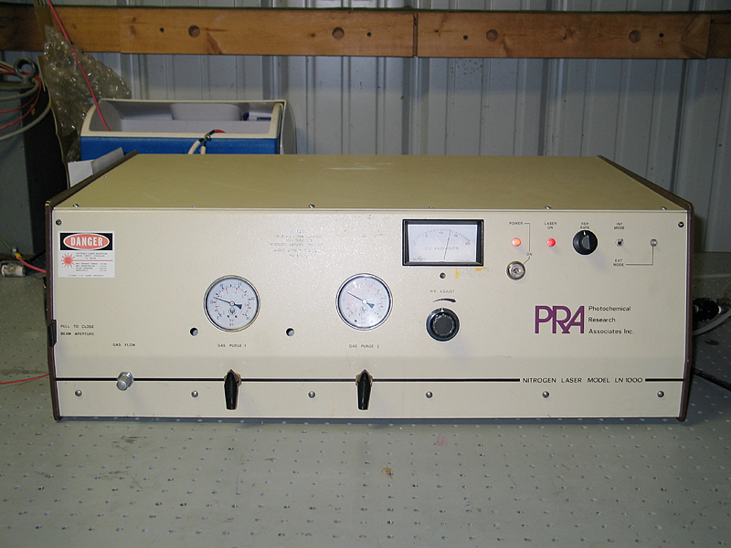
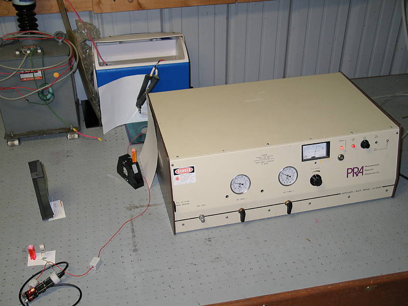
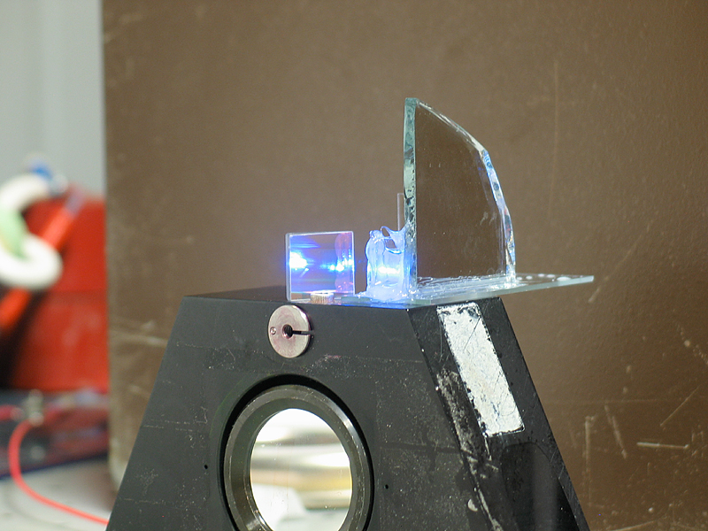
The PRA LN-1000 nitrogen laser operates at room pressure, and puts out pulses that are approximately 800 psec long. (At least, that was what the mfr stated. Most room-pressure nitrogen lasers seem to have pulsewidth between about 600 psec and 1 nsec, and I do not yet have an easy way to check, so we’ll take it as given for now.) The LN-1000 is rated to deliver about 1.5 mJ per pulse, which corresponds to about 2 MW peak power. Here are two views of it:
We won this laser on eBay, some time ago. When it arrived I found the key broken off in the lock (fortunately all the way in, so I could turn the switch with a screwdriver); some of the screws were missing from the case, and it was obvious that not all was well within.
I dusted out the HV section and tried running the laser. It mostly self-triggered, emitting various snorts and barks, and it only occasionally lased; but it was clearly a real machine and not just a pile of scrap. I disassembled the primary spark gap, cleaned it, and adjusted one of the electrodes. While doing this, I noticed that the back end of the housing was pitted and eroded from sparking, as was the aluminum plate it mated to. I wire-brushed these to clean them, but it was clear that I needed some highly conductive material between them to prevent a recurrence. There are some conductive pastes and greases, typically heavily loaded with silver, but I don’t think I have any. Fortunately, Gordon Garb was visiting, and he had some PMC (“Precious Metal Clay”) with him, in several forms. I used a small amount of the “glop” version, which comes in a tiny syringe, as conductive paste. PMC is well over 90% metal, in this case silver, and it worked quite nicely.
The trigger system quit while I was testing, and I eventually discovered that one of the chips (it uses two MC1455 timers and one other old-style CMOS device) had shorted out. I’ve got a temporary replacement in place, and the laser is now operational. I have been running it at about 15 kV, with insufficient pressure (see note) at the inlets.
[[NOTE, added 22 December, 2010: I had originally thought that I was running about 175 psi into the box, but careful examination of my regulator reveals that I was reading the wrong scale: the regulator puts out a maximum of 30 psi. I have now ordered a regulator that can deliver up to 150 psi, which is more than enough — the laser probably wants only 80-100. (It uses nitrogen to pressurize both spark gaps.)]]
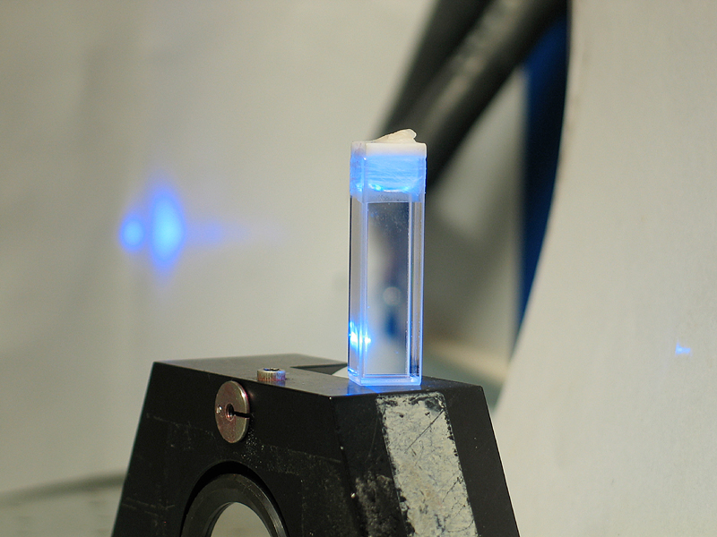
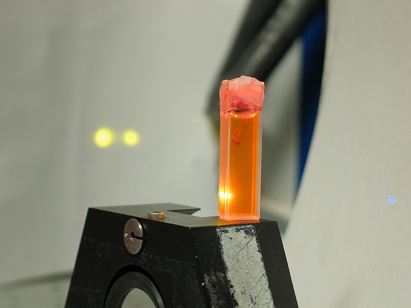
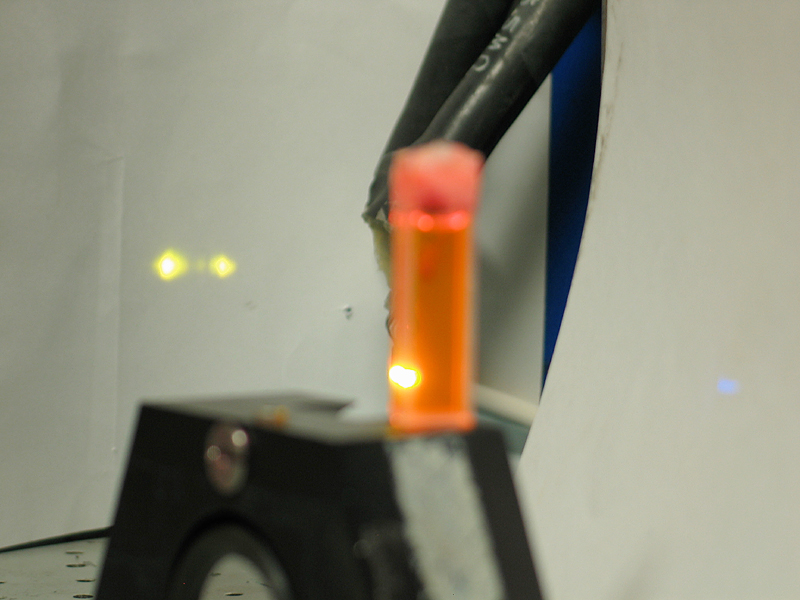
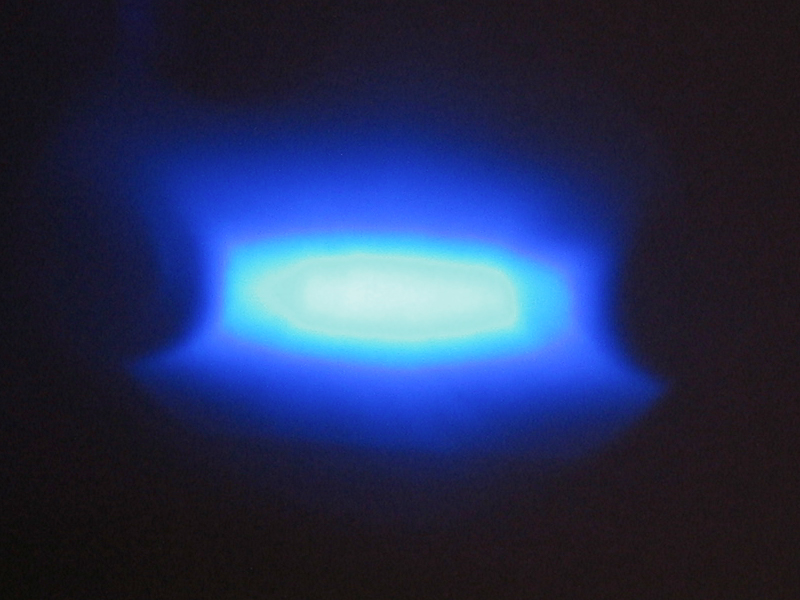
First, using. Here’s what happens when I focus it into a cuvette of 7-Diethylamino-4-Methyl-Coumarin (left) or Rhodamine 6G (middle, focused on the cuvette, and right, focused on the target in the background):
I am now setting up a prism and two mirrors so I can tune the dye output. I’ll add photos when that setup is complete.
(Added on 25 May, 2004)
Ahem. That didn’t work.
If I understand this correctly, here’s why:
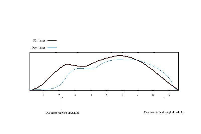
In diagram #1, we have something that I will politely describe as “an artist’s representation” of an ordinary low-pressure nitrogen laser pulse (heavy dark line), and the output of a dye laser driven by that pulse (blue line). The timescale is in nanoseconds — a low-pressure nitrogen laser pulse is typically 5 to 10 nsec long — and the output power units are totally arbitrary.
[Note, added on 24/25 January, 2006:
Both of those diagrams probably have the dye laser output lasting too long. Here is an actual pair of oscilloscope traces (drawn over by hand because I was unable to select them in the Gimp), showing the output of a low-pressure nitrogen laser (magenta), and the output of an untuned 4-Methyl-Umbelliferone dye laser being driven by it (green). The oscilloscope was triggered by the output of the photodiode in both cases, which means that the dye laser pulse is shown a bit early here, and should actually be displaced a little to the right of its current location.
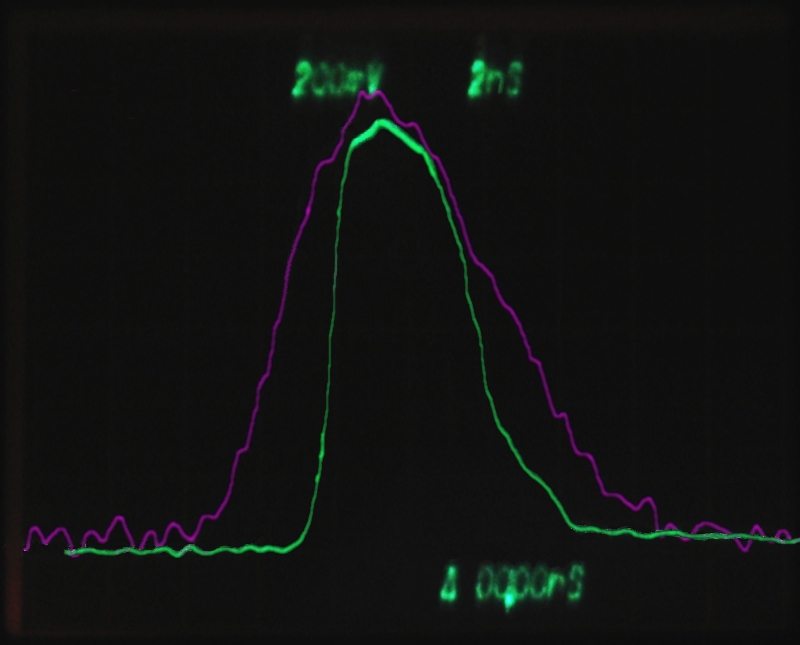
The dye here is using one of the cuvette walls as its output coupler; I was able to position a high-reflectance mirror on one side of the cuvette, but did not have time to make a full-blown tuning setup. The dye pulse has a much sharper risetime than I guessed when I drew the diagram on the left, above, and it ends sooner. So much for guesswork.]
The physical dimensions of the dye laser are such that the light inside it gets to make as many as 15 to 20 transits while the laser is above threshold. (Remember, light travels roughly 1 foot per nanosecond in air, so if the dye laser is 4 inches from end to end, light can make one full transit in 2/3 of a nanosecond or so.) This provides quite a bit of feedback, which is what allows you to tune the output wavelength — without feedback, the dye lases at whatever wavelengths it lases at, and you can’t do much about that except to tweak the concentration and maybe the solvent. With nitrogen laser pumping, you don’t even get to do a whole lot with the concentration, because if you don’t get the dye solution to absorb most of the pump pulse in a shallow region, you typically fail to reach threshold.
I should probably point out that a dye laser emits thousands of watts of spontaneous output. This utterly swamps anything less than thousands of watts of feedback. (If you’ve ever tried to tune a pulsed dye laser by injecting the output of a HeNe, you will have observed that there was no effect at all. Even if you put the dye cell inside the HeNe’s optical cavity, where there are watts of circulating power, it still won’t work.)
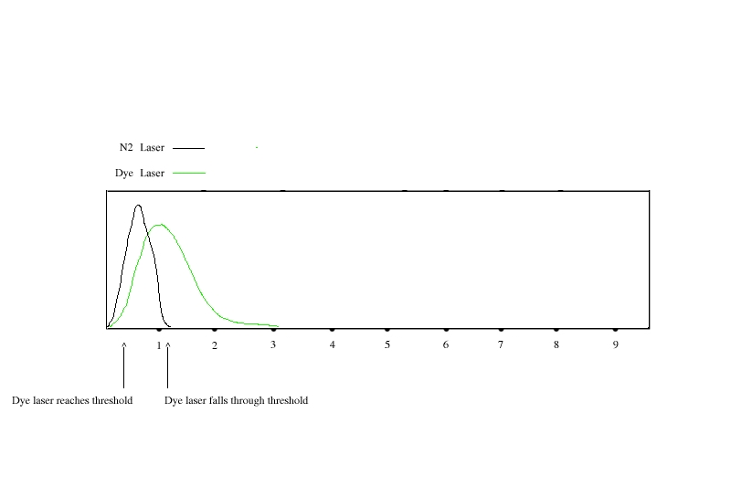
In diagram #2 we have a room-pressure nitrogen laser pulse in black, and a corresponding dye laser pulse in green. Mind you, I haven’t actually collected a dye laser pulse from one of these with a ’scope, so I’m partly making this up (“artist’s representation” again), but it makes sense to me — even though the dye lifetime is 6 to 10 nsec (for things like Fluorescein and Rhodamine 6G), we’re continually extracting energy from the dye laser, so it won’t run for very long after the nitrogen laser turns off. The pulse from a room-pressure nitrogen laser is appreciably less than 1 nsec long, however, which means that the entire dye laser pulse is about as long as 2 or 3 transits of the cavity if the dimensions are the same as they are in the example at left. This fails to provide adequate feedback, and the dye laser’s output is not tuned.
There are two obvious ways out of this.
I should also note that it was wretchedly difficult
to align the parts of the dye laser; but that’s not a
show-stopper, just a pain in the neck. I’ve succeeded
in the past, so I know it can be done. (Note, added
later: in fact, the narrow laser proved to be fairly
easy to align. Part of this is the fact that one of
the mirrors gets aligned during construction, and
ceases to be an issue once it’s right.)
Milan Karakas asked whether I could take a photo of the guts of the laser head. Unfortunately, it is sealed inside a metal box. (See the “Innards” section, below, for a look.) What I can do is take a photo of the reflection from the front of the cuvette, which provides an image of the plasma inside the laser and the profiles of the electrodes. Unfortunately, these things are a lot easier to see in person than in a photograph. This is about as good a picture as I’ve been able to obtain, so far:
This is a multiple exposure — the camera held its shutter open for a full second, and I had the laser doing perhaps 5 pps. A single pulse doesn’t provide enough brightness. What you’re seeing here, btw, is the fluorescence of the paper target, not the actual UV reflected from the cuvette. While I can’t really show it here, the brightest region in the plasma seems to move around a bit from shot to shot.
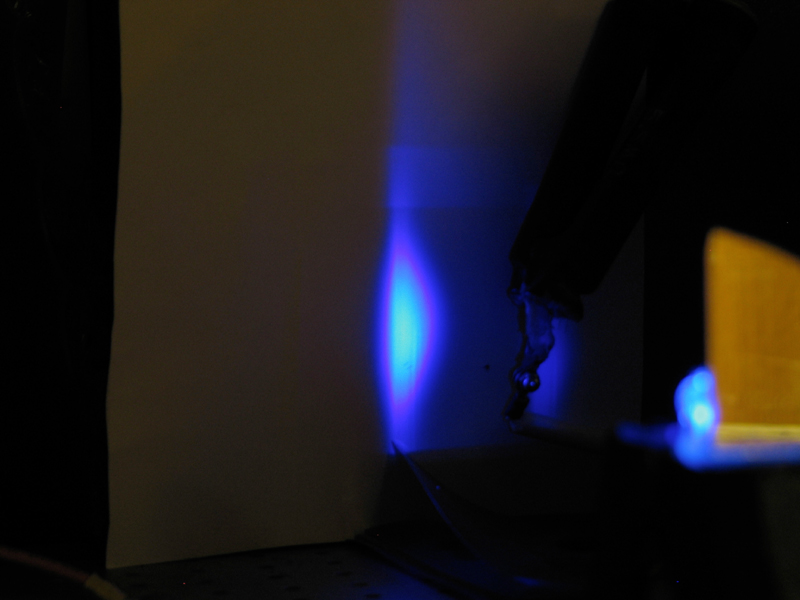
Here’s an untuned dye setup, and two pictures of the output — one taken in roomlight, and one in the dark:
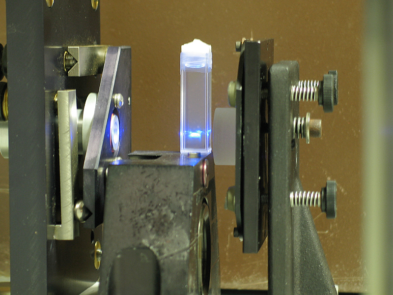
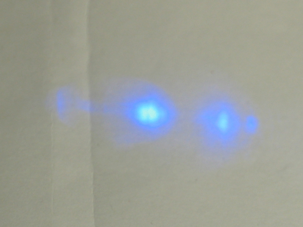
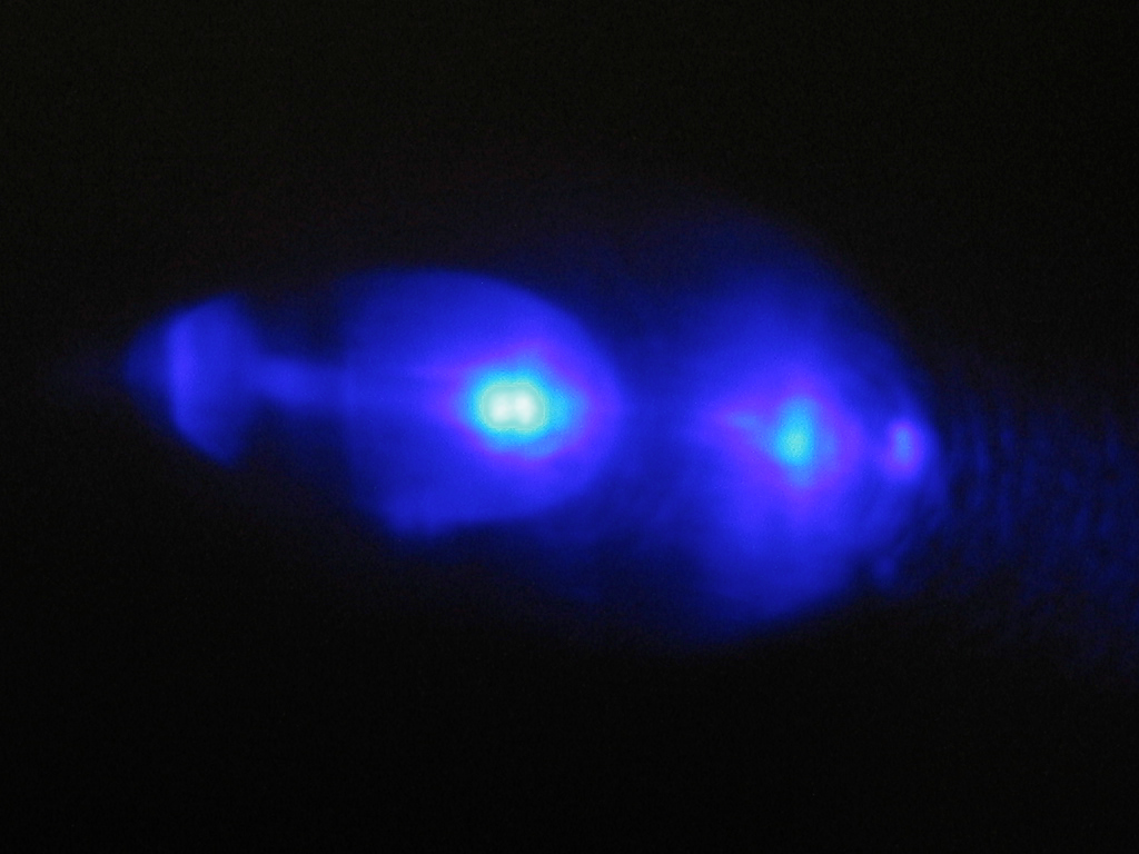
As you might guess, the mirrors are not fully aligned. Even so, the dye is lasing fairly brightly.
I’m thinking about the design of a small cuvette with integral "max ref" mirror (actually a piece of overcoated aluminum front-surface mirror, probably with about 95% reflectance) — I figure that if I can get the transit time inside the dye laser down to 150 psec or so, I have a fair chance of tuning it. Whether I can actually bring that off remains to be seen.
(29 May, 2004)
Well, that worked. Here are some photos. First, the dye cell, with a grating standing to its left. It’s rude and crude, but it works. (I’ve revised it since this photo was taken; the page with the photographic tuning curve for 4-MU shows the new setup.) Second, the output with no grating — we’re using the first-surface mirror and the dye (2 or 3 cc of 95% ethanol, in which I have dissolved a small amount of 4-Methyl-Umbelliferone and a drop or two of strong ammonia-water); the window opposite the mirror is deliberately misaligned, so it can’t provide much feedback.
Now a few tuning photos. First, here’s what happened when I put Rhodamine 6G into the cuvette:
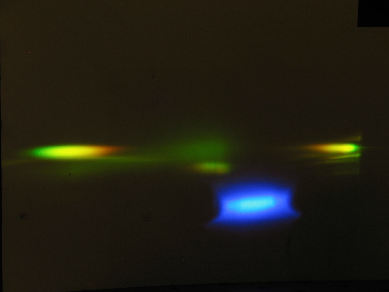
What I think happened here is that the gain in the Rhodamine is so high that it was able to lase in superfluorescent mode, in a range of wavelengths at once. The grating splits the output. (These photos were taken yesterday; I now have things arranged so that the grating is probably in its first order, and when I get a chance I’ll try Rhodamine again.)
Next, I’ve put a sort of photographic tuning curve for 4-Methyl-Umbelliferone on another page.
(02 June, 2004)
Last night, I aligned the grating. I hope I’ll be able to add some diagrams of what I think is going on with grating alignment, because it is a cute puzzle. I only just figured out how to think about this today, though, and haven’t had time to generate decent pictures yet. In any case, at this point I only have to do minor tweaking on the other axis when I change the tuning. This is a distinct improvement.
I suspect that the round-trip transit time in the dye laser is on the order of 150-200 psec (it depends somewhat on the position of the grating, but the thing is about 3 cm across), and I’m guessing that the dye continues to lase for some hundreds of psec after the end of the pump pulse. I don’t yet have a way to check that, but eventually I hope to. It will take a very fast photodiode and a very fast oscilloscope, though...
(02 June, 2004)
We have some Scientech power meter heads that we acquired on eBay, and today I put one in front of the LN-1000. It registered a small voltage, too small to look at easily, so I put my little instrumentation amp on it. (This is a 100X amplifier that I built some time ago; it lets me read a type S thermocouple with an ordinary digital multimeter, and I use it when I’m firing my gas test kiln.) With the amp in place I found that I could get a decent reading on the oscilloscope. After a few dry runs, and after I tweaked the laser for best output at 4 pps, I brought the head to the same output level with a power supply, simultaneously measuring the voltage and current with a pair of meters. It took 0.419 V and 10.23 mA, which says I’m getting about 1.07 mJ per pulse. (The laser was probably rated to produce 1.45 mJ when it was new.) Considering the fact that this laser was nonfunctional when we got it, and had real problems, I think we’re doing reasonably well.
At some point I may clean the second spark gap and the laser
channel, but for now I think I’ll let things stand as they
are. The output is well over 1 MW peak power, and it is just
fine for driving the dye laser I’ve constructed.
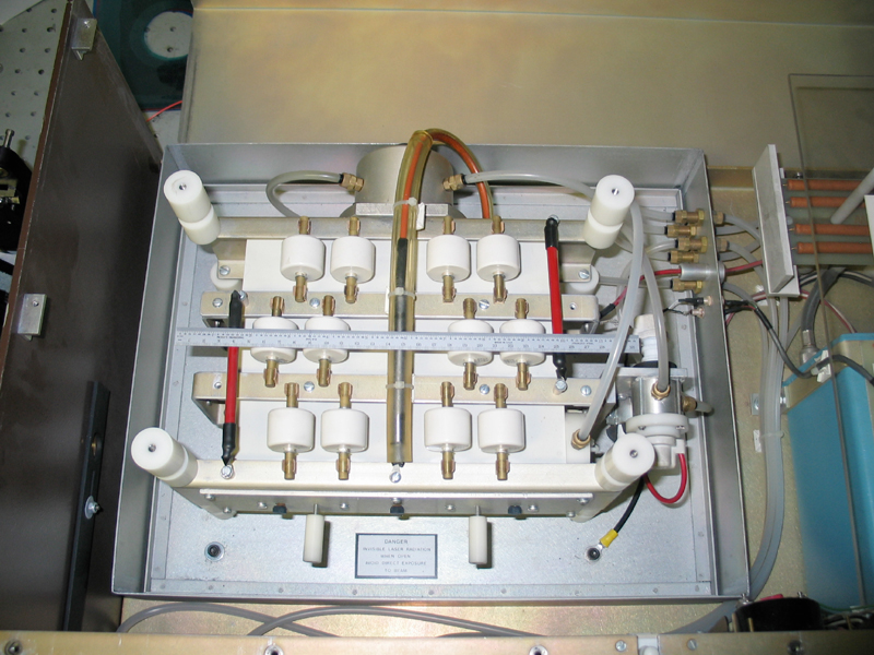
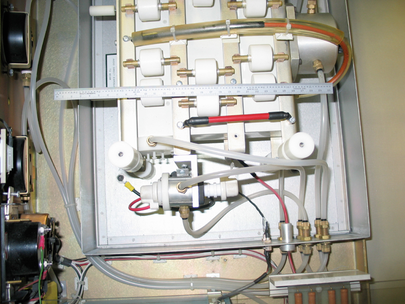
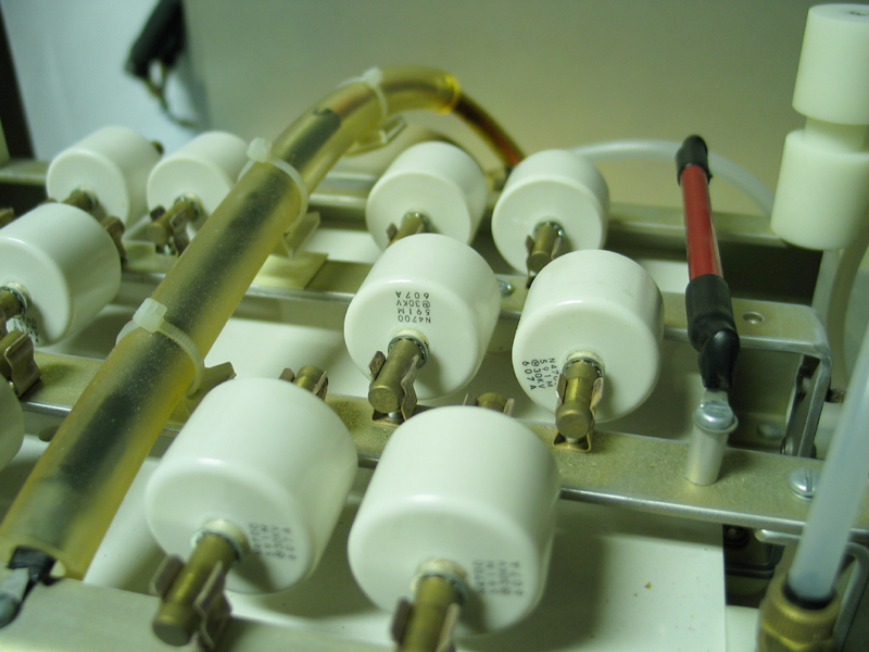
Milan Karakas asked for some photos of the interior
workings of the LN1000, which seemed like a very fine
idea. I’ve had trouble taking shots of the laser
channel, because I’m reluctant to open it up, but I
got one mediocre one of the end. (Milan has since
suggested using a lightpipe, and when I have time I’ll
try that.) Here are the images —
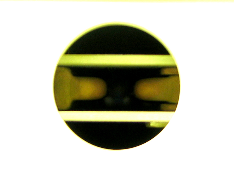
I had to massage one of these (it was grossly
overexposed), and as I mention, I did serious tweaking
on the shot into the end of the laser, showing the
electrodes and what I think is the preionizer. I must
also apologize for the greenish color of two of these
— I had the camera’s white-balance set wrong.
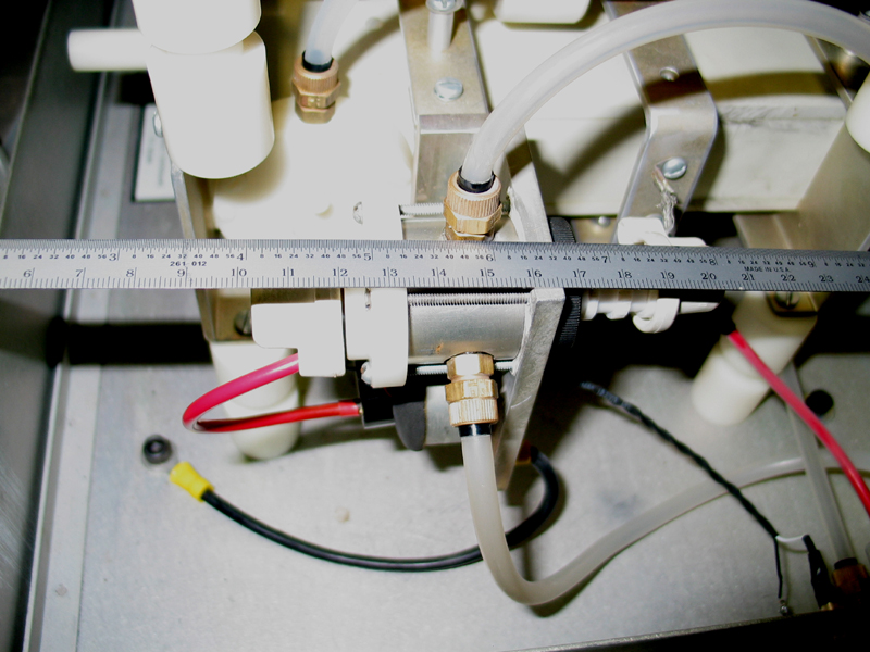
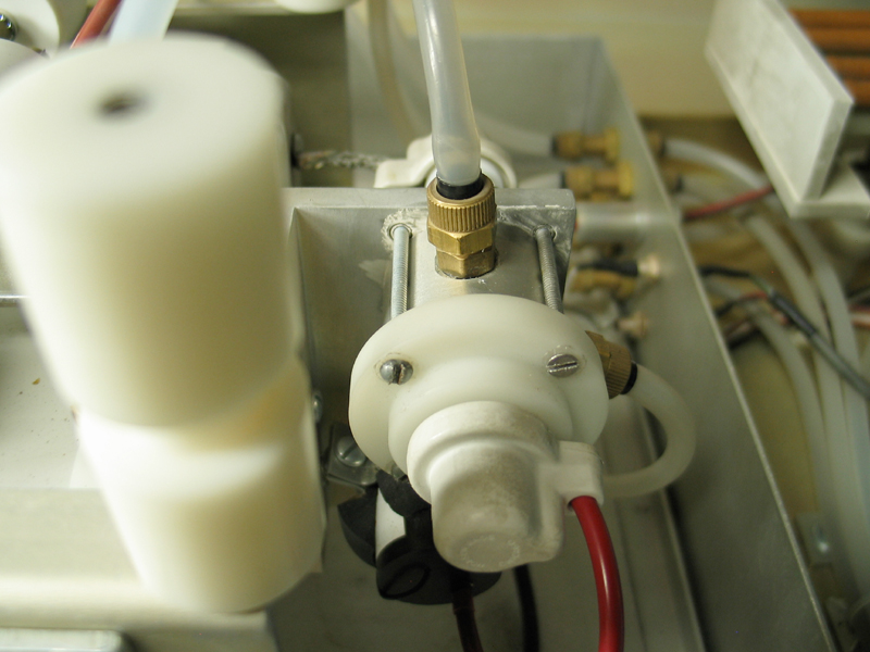
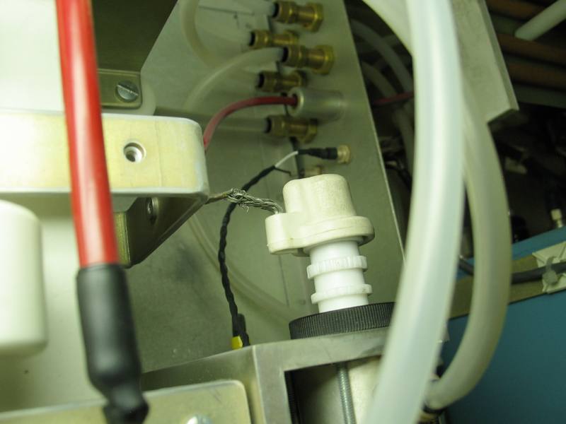
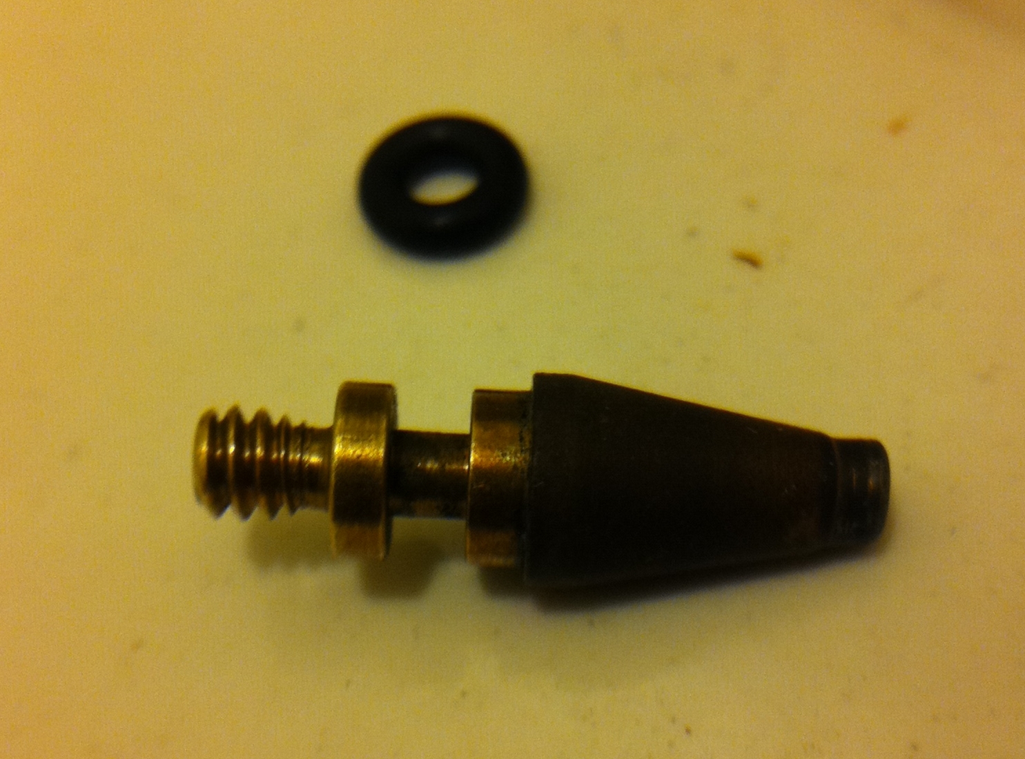
[[NOTE, added 22 December, 2010: In the process of
bringing this laser back online for some new work, I had
occasion to disassemble the primary spark gap, which is
shown in the second row of three images. I have added,
below that row, a photo that shows the tip of the center
electrode, with the new o-ring I was about to install on
it. Sorry about the focus; I took the photo with a small
hand-lens in front of the camera on my telephone.]]
If you look at the end of the primary gap where it meets
the aluminum plate, btw, you can see a little of the PMC
I smeared on the joint to prevent further sparking and
erosion.
The secondary spark gap is hiding behind the guts of the
laser, at center rear. (Top of the first photo,
righthand side of the second. There is a red HV cable
curling around it.) I haven’t opened up that gap,
and I’ve discovered that the laser will operate
through a fairly wide range of settings on it, so
I’m basically leaving it alone for now.
The laser head in this machine appears to be nearly
identical to the one in the PTI GL-3300 laser;
here’s a link to
their online manual for it. I think the spark gaps
may be a bit different, the rest of the design seems to
have some differences, and the enclosure is radically
different, but the design of the laser head is clearly
identical or very nearly so.
(22 December, 2010, late evening)
I am in the midst of a project that wants brief pulses
of excitation at 337 nm or so, and this laser seemed to
be nearly ideal for the purpose, so I set about bringing
it back online. I soon discovered that it would not hold
any pressure, and when I investigated further I found
that the main o-ring in the primary spark gap had aged
out, and that the secondary o-ring was not even present.
I am now entirely at a loss to understand how I ever got
the thing to work in the first place.
I have already mentioned the fact that it wants more
pressure than I can currently deliver, but I managed to
get some operation at 30 psi and somewhat reduced voltage
earlier this evening, after I replaced both o-rings in
the primary spark gap. I anticipate getting considerably
more energy per pulse (and more even operation!) when
the new regulator arrives.
(23 December, 2010, evening)
The new regulator has arrived, and I have installed it.
The little regulator on one of the inlet lines does
exactly what I thought: it sets the pressure on the
second spark gap. The PTI manual suggests 45 psi, so
that is what I have it set to.
Unfortunately, with 80 psi on the inlet and gap 1, I do
not get triggering. I’m essentially certain that
this is because the adjustable electrode has worn down
too far, and I can’t get it close enough to the
main housing. However, if I decrease the inlet pressure
to 60 psi, I get occasional triggers at about 19 kV,
which is probably acceptable for now. I will be talking
with the folks at PTI about getting a new tip for the
adjustable electrode. (I bought 2 o-rings of the
relevant size, so I will be able to install a new tip
relatively easily)=(...but see below.)
Late addition, 2013.1028: I checked with PTI a
while back. Turns out that their part is a single piece;
it does not have a replaceable tip. It is also a bit
pricy, around $265, which is more than I can afford, so
I made a little extender by turning down a thin hex nut
on a lathe. I generally run the laser at only a very
slow repetition rate (see below for a caution about
this), and I am hoping that the tip will last for quite
a while. As of today I have cleaned SG-2, and I’ve
done a bit more adjustment of SG-1. The laser is running
better now, but it is clear that the braid from the back
of SG-1 to the frame is badly frayed, and needs to be
replaced. Working on it — I’ve purchased a
length of silver-plated braid from
Electronics Goldmine,
and we’ll see if I can make a usable connector
out of it.
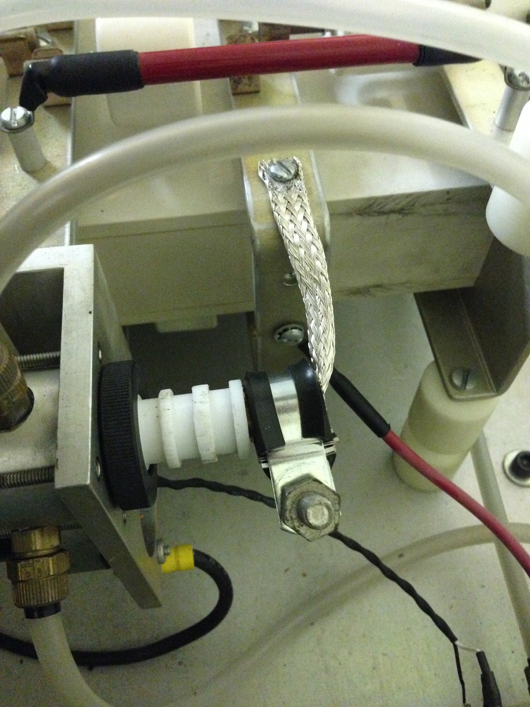
Further addition, 2013.1030: This worked out, and I
replaced the braid yesterday. Here’s a photo:
Notice that the new braid connects to a different place
on the frame. Notice also that I am not using the
original cap on the spark gap; this braid is large
enough that it easily expands to fit around the
terminal, and I’ve just clamped it on. I already
have one layer of thin cardboard between the braid and
the rubber padding on the clamp, but I’m not sure
if the clamp is firm enough; eventually I will take it
off and check. It is easy to add more shim inside the
clamp if that appears to be needed.
(2013.1030)
Holger (who can be reached via email to lsei1 at yahoo)
sends the following adjustment procedure, which I have
slightly edited and formatted for consistency and ease
of reading:
CAUTION: PTI recommends not running at 1-2 Hz for
very long. It stresses the transfer boards, and can
cause burnthrough that will lead to low power and
misfiring ...and is not repairable; the boards would
need to be replaced.
Turn up the voltage slowly, and watch the needle. It
should start to twitch at 10 kV. if the gap in SG-1 is
too narrow you will need to stop the system, open it up,
and back out the electrode a bit. If SG-1 starts firing
higher than 10 kV it’s bad; move the electrode in.
[To move the electrode: remove the cap that connects the
braid to the electrode. Loosen the black locking ring
that you can see in my photo of the new braid, above.
Grasp the teflon insulator carefully with a pair of
ridged pliers (teflon is very slippery), and rotate it a
fraction of a turn. Tighten the locking ring, put the
cap back on, check the result, and tweak if/as
necessary.]
Note: SG-2 is easy to adjust. If it starts at
some other voltage, turn the black plastic covered knob
on the back 1 full turn per 1.5 kV; then give it 3-5
minutes to work in before adjusting it again. The laser
should then be stable for about 20-30 minutes before
misfirings begin; they can often be remedied by purges
and needle-valve flow adjust. Sometimes a slight
temporary bump up in voltage can help, but you should
bring it back down when the laser is behaving again.
Note: When you clean the white plastic inside
either spark gap housing, do not touch the fuzzy
graphite deposit around the entrance hole. It’s a
fine dusting of graphite powder that is the preionizer.
Removing or damaging it prevents the spark gap from
firing correctly.
(2013.1030)
Despite the fact, mentioned above, that the gas hoses on
the LN1000 seem to be reversed, so that SG-1 is at
higher pressure and SG-2 is at lower pressure, I was
able to adjust the gaps to meet the description above,
and the laser runs better now than it has at any time
since we acquired it. When I get a chance I’ll
swap the hoses and redo the adjustment. Meanwhile,
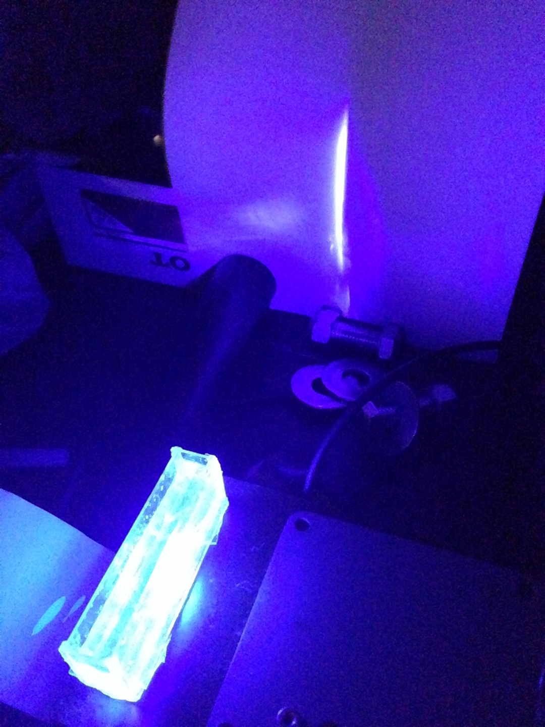
here’s some “DTC” in water and
isopropanol, in a cuvette with misaligned side windows,
pumped by the unfocused output of the LN1000:
(The misalignment is deliberate — this cuvette is
intended for use with a low-pressure nitrogen laser and
external optics.)
More as it transpires...
My page about the Sci Am laser includes several relevant references.
To the top of the LASERs section
[Note: The links are to files in my archives. If you want to
see the Joss Research Website, you can find it
here.]
My new research homepage, as of early 2013
My email address is a@b.com, where the a gets replaced
by my first name (jon, only 3 letters, no “h”), and
“joss” replaces the b.
My phone number is +1 240 604 4495.
Last modified: Tue May 9 12:24:23 EDT 2017
The Innards
Rework and a Puzzlement
Adjustment Information from Holger Jaenisch:
Background and References:
This work was supported, until early 2013, by
The Joss Research Institute
Formely located at 19 Main St.
Laurel MD 20707-4303 USA
Contact Information: