(2006 April 18 ff)
Please note that I have made no effort to optimize the concentrations of the dyes; they are just as they came out of the markers, with the exception of the Red, which I diluted slightly and added ammonia to (see the text for more information, and see the main page of this Report for my extraction method.)
For an enlargement of any of the photos, click the small one. Most of them are merely resized from the originals, and if you have some reason to want to see the original pixels you can change “.10c.” in the filename to “.22c.”. (If an image is cropped, I usually give specific instructions for it.)
Before you can tune a nitrogen-pumped dye laser, you have to align it. This turns out to be a nontrivial exercise.
The first step is to acquire or build a cuvette. The cuvette has to have a rather flat front window that passes ultraviolet light at 337.1 nm, and it needs to have side windows that are of at least reasonable optical quality. It helps if the side windows are slightly misaligned with each other, to help suppress the parasitic lasing that occurs if the dye can use the windows as mirrors.
I will try to provide photos and/or drawings of a homebrew cuvette that works reasonably well, but in the meanwhile I’m going to use a commercial fused silica one. That will let us observe the parasitic lasing, and we will have to evade it as well as we can.
Once you have a cuvette, you need a dye solution to fill it with. The dye needs to absorb almost all pump light in about the first 0.5 mm of depth — as I showed on the first page of this set, if the pump light penetrates too far into the dye it becomes very difficult to achieve lasing at all unless your nitrogen laser is extremely powerful. [More than 150 kW, certainly.] Fortunately, if you don’t try to dilute them very much, most of the dyes you can extract from fluorescent markers are reasonably concentrated, and some of them will meet this requirement. (The dye also has to fluoresce efficiently; some marker dyes are better than others.)
Next, you need to be able to focus the output of your pump laser into the front window of the cuvette. I got a 6" spherical mirror with reasonable focal length from The Surplus Shed, but you can probably work something out even if you are unable to buy a suitable mirror or fused silica lens. (I may get into this later, especially if anyone actually asks for more information about it.)
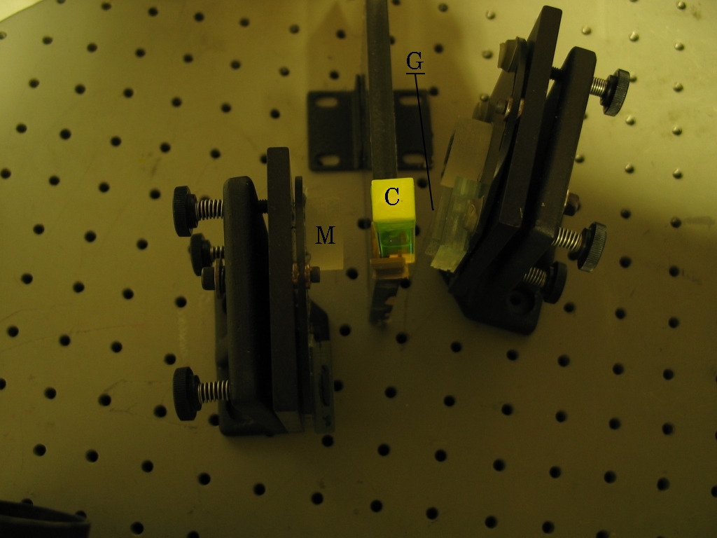
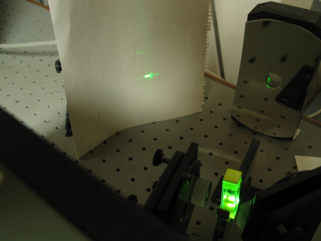
Here is an overview of my [decidedly informal] setup, with a Mirror, a Cuvette, and a Grating, which I have noted on the enlargement:
I usually put the mirror closer to the cuvette, but a wee bit of distance will give you a better-defined beam. Also, the grating is at an unrealistic angle in this picture.
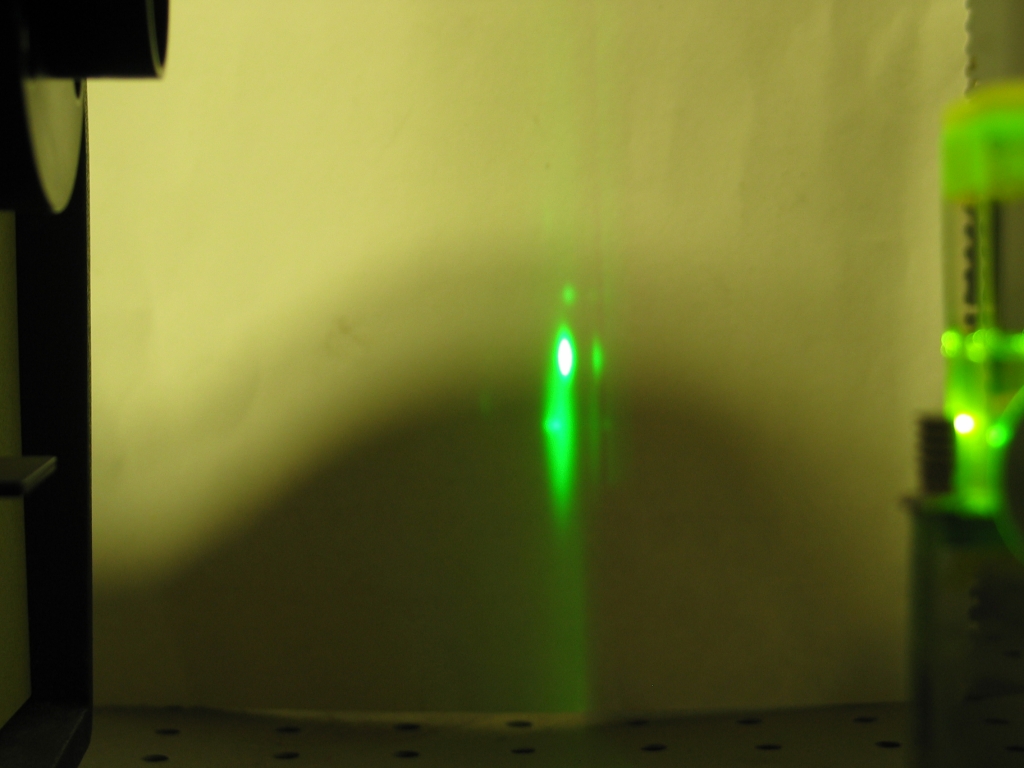
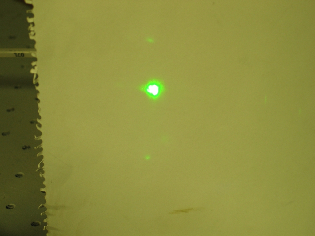
If you just set up the cuvette with dye, the nitrogen laser, and the focusing lens (but no mirror and no grating), you are likely to see a pattern that looks something like this:
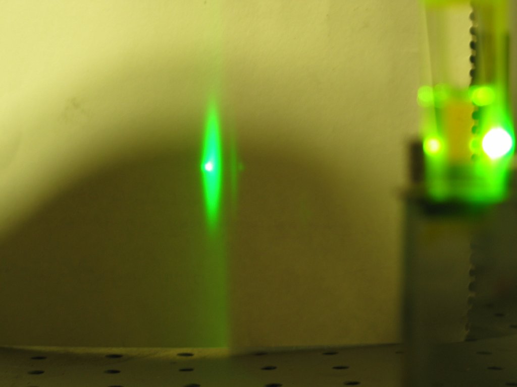
The large fuzzy green area may be partly caused by scattering from junk in the dye, but certainly the bright dot in the middle is superfluorescent lasing (or ASE, as I discuss on the previous page).
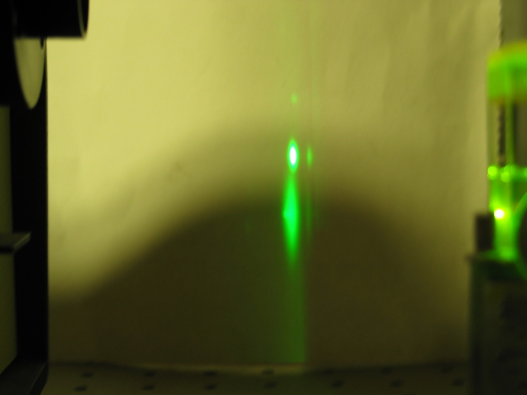
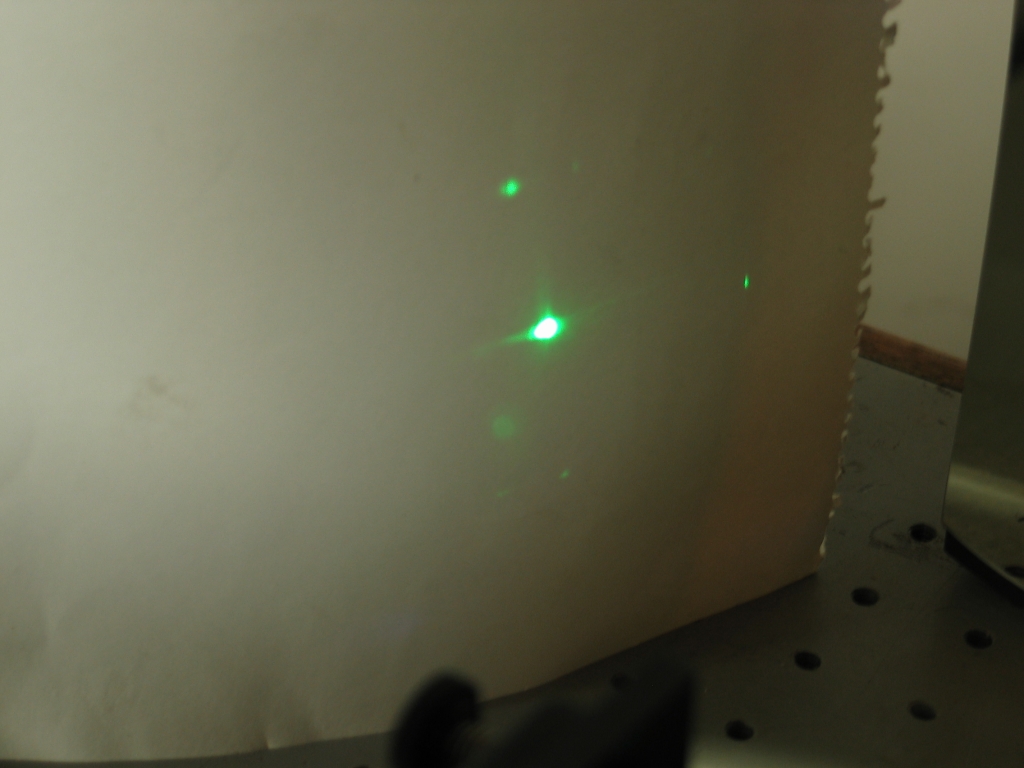
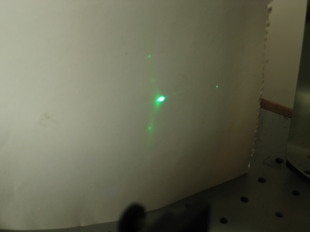
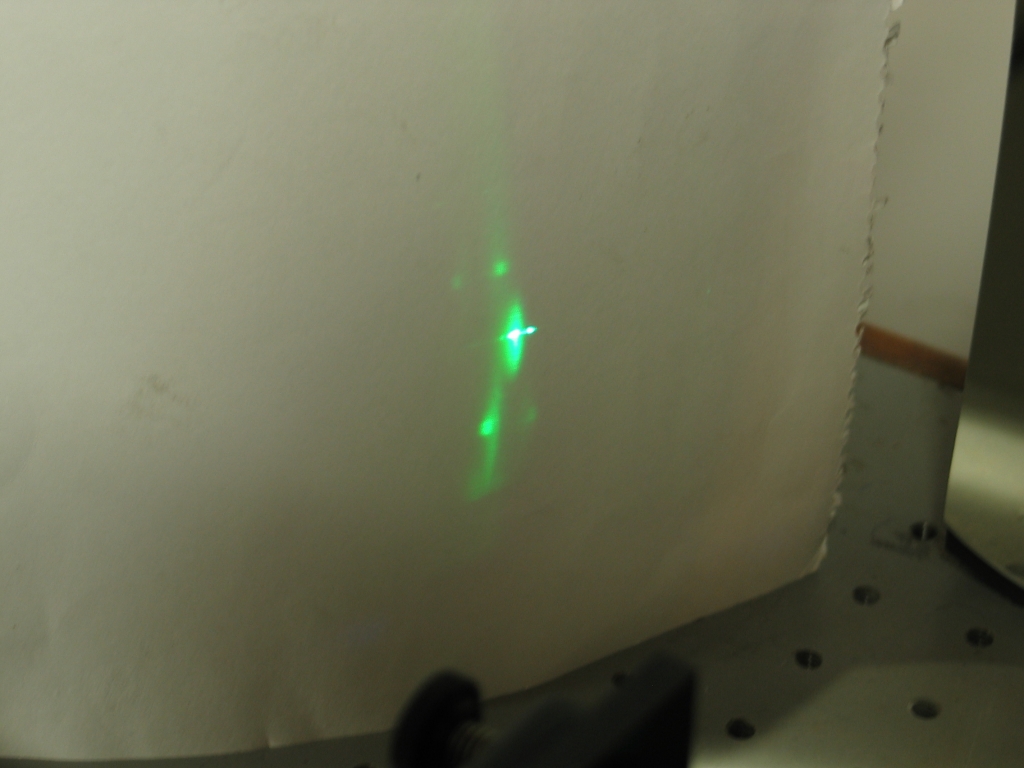
The precise look of your pattern will depend on a number of things, including the shape of the focused pump beam on the front of the cuvette, the concentration of the dye, and so on. Here are three patterns I got with dye from a hot-pink marker:
The first few pulses from the nitrogen laser gave me a reasonable pattern, but it quickly changed to what you see in the first picture. That told me the dye was not very good. I then added a drop of ammonia (if you try that, make sure you use ammonia that is clear and uncolored!), which seemed to help a bit (it will only work with a few dyes, but is worth a try if something is marginal), and I was able to get some lasing; but I had to focus the pump beam to a very sharp narrow line across the front of the cuvette. The picture on the right shows a much better pattern, but I still don’t like the look of it. I would expect a single dot, not a double one.
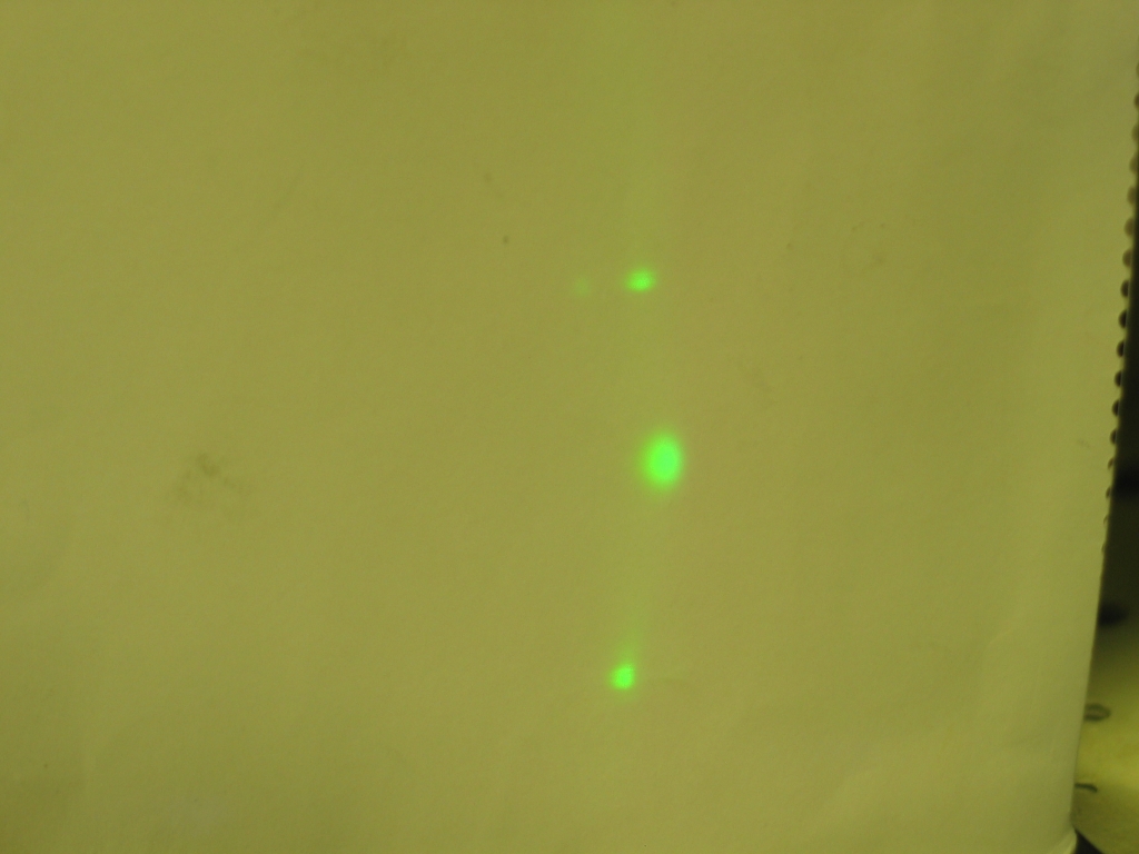
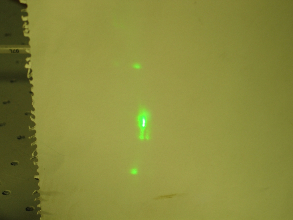
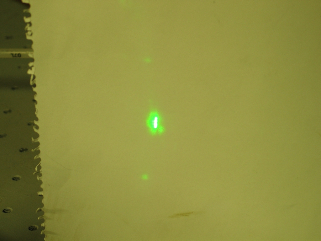
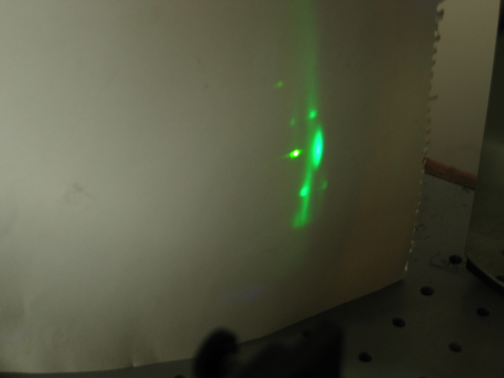
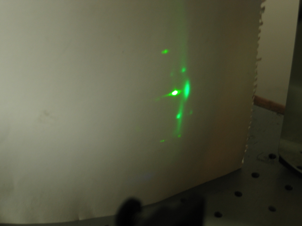
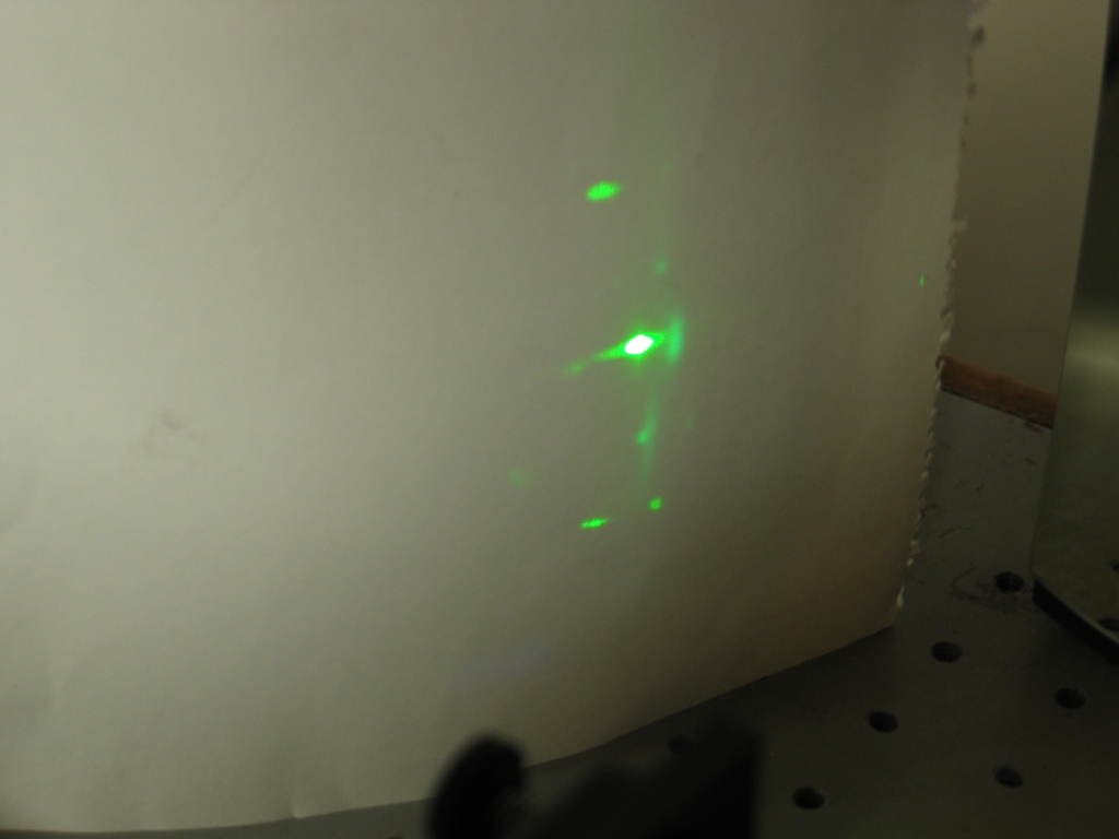
Be that as it may, once you have observed the pattern your cuvette puts out when it doesn’t have any external mirrors aimed at it, you get to add and align a mirror. Here is a set of photos, taken with yellow-green dye, showing parts of an alignment process:
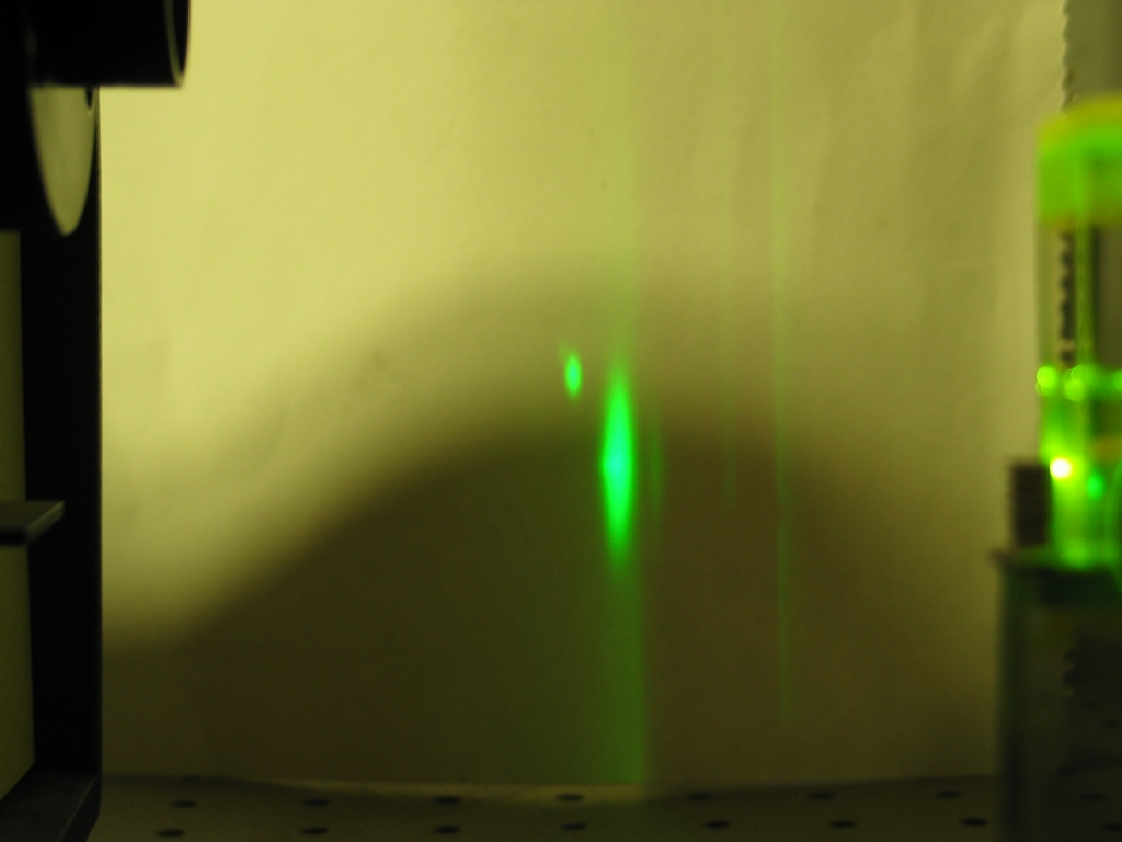
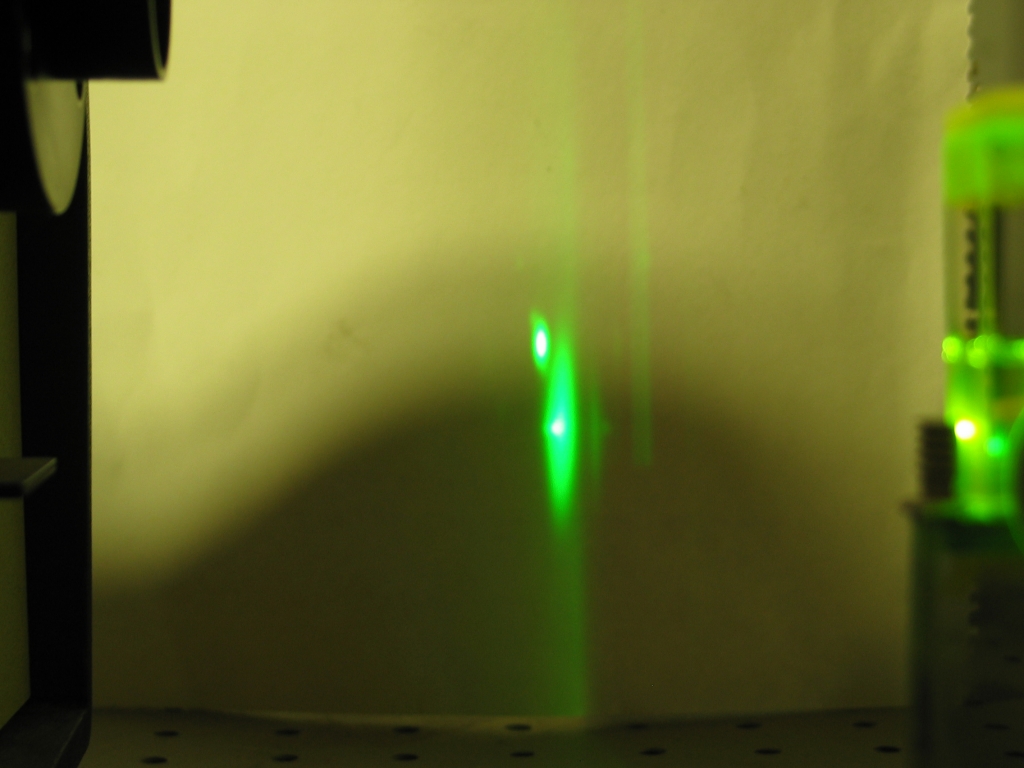


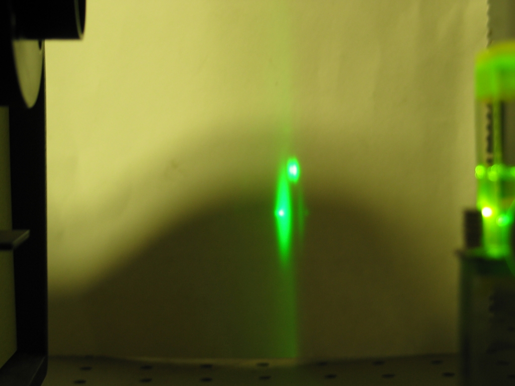
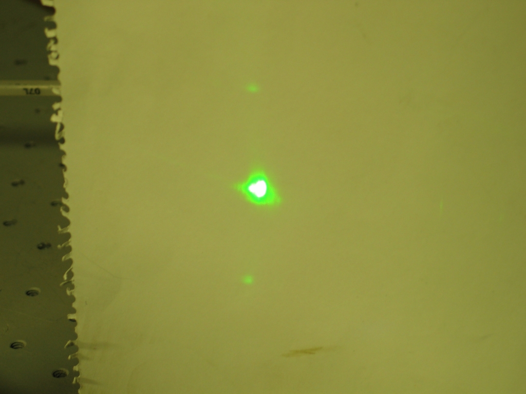
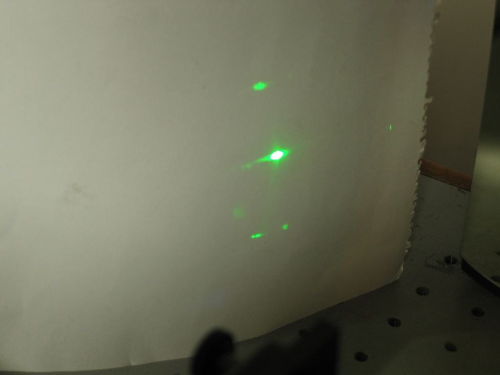
In that series I “walk” the reflection from the external mirror across the target; the middle image looks about okay to me, and is a reasonable place to start as far as horizontal alignment goes. Let’s take a brief look at vertical alignment:
Notice that in the second picture, I have pointed the mirror up a little. I actually think that the first one is a better alignment, but it depends on various aspects of your setup, so be ready to try a variety of options. At this stage, unless you are really expert or have information I lack, you are only performing preliminary alignment in any case. You will get to do some tweaking later.
Once you have a mirror in place and at least vaguely aligned, it’s time to add a grating (or a prism and a second mirror). I happen to have a grating on hand, so that’s what I’m going to use.
I typically do not get tuned output when I first put the grating into place. This is no surprise, actually, as there is no particular reason to expect it to be aligned with the mirror, nor to be at a viable angle. I usually have to walk it around quite a bit before I see any trace of tuning, and sometimes I have to angle it up and down as well. That process can take a while, and can occasionally be quite frustrating. It helps to stay calm, and to be willing to tweak almost every possible variable. [It also helps to think very clearly, so that you will be able to tell which variables are the best ones to tweak.]
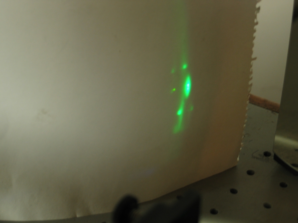
Here are some photos of a grating alignment process. We’ll begin with no trace of tuning, and skip some of the walking across images because they all looked essentially identical. I had to get almost to the left edge of the target before I caught anything; in the second photos, you can see some splotchy stuff that is clearly different from the smooth-edged blob of the first photo. From there, I walk the grating up (or down, depending) until it is nicely aligned with the mirror. Achieving that alignment usually minimizes the parasitic beams, though there are circumstances that can interfere (for example if the mirror is not aligned well with the pump beam, or if the pump beam is too closely aligned to the tilt angle of the cuvette, assuming that the cuvette has parallel windows, as this one does).
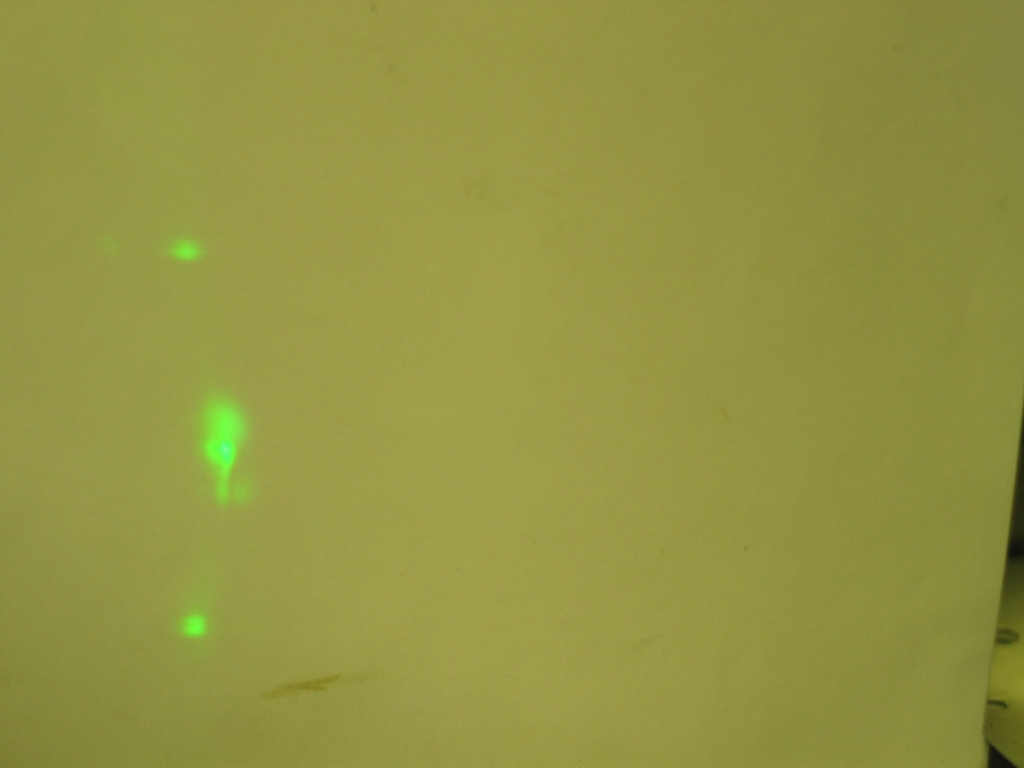
As you can see, in the last photo I have angled the grating too far up to match the current setting of the mirror. (The next-to-last one is about right.)
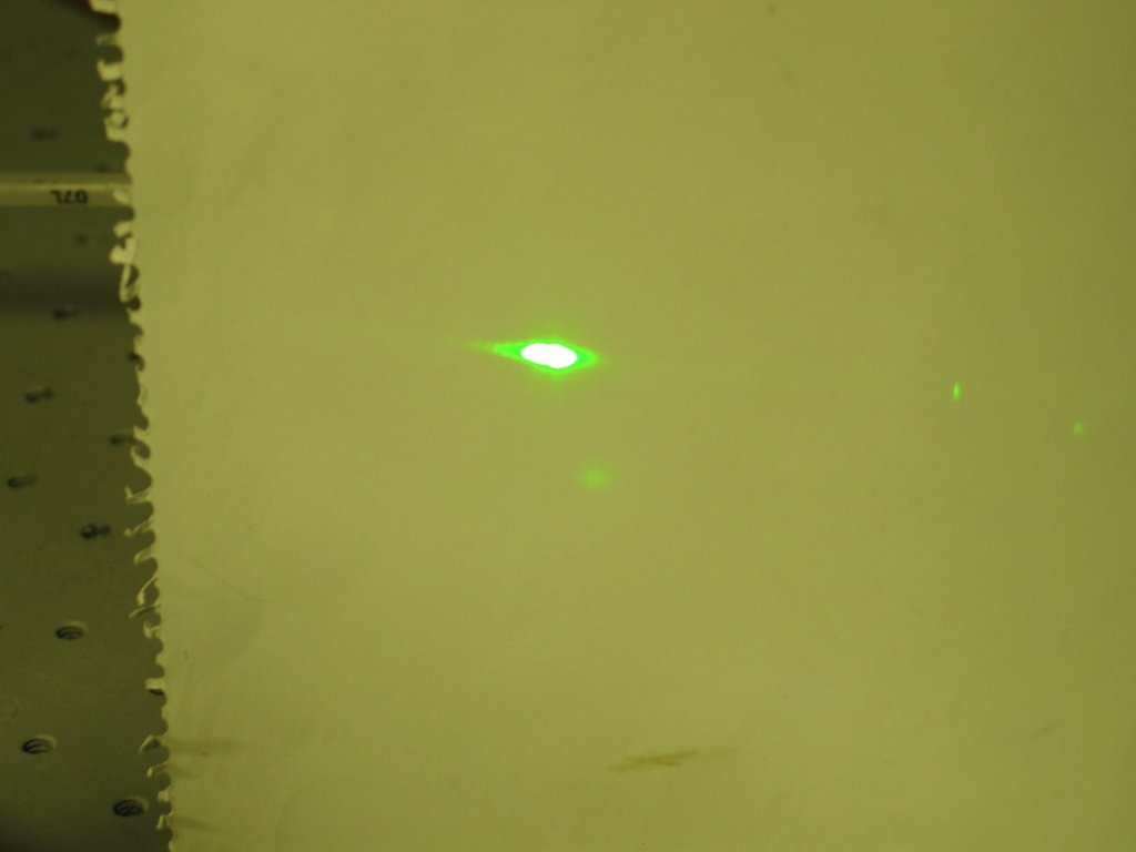
Once I get good agreement between the mirror and the grating, I can try to refine the arrangement between them and the cuvette. I can also try to refine the shape and angle of the pump beam on the front face of the cuvette. With a very good dye, I can easily get away with a pump beam that looks more or less like this:
(Nitrogen lasers being what they are, the beam may or may not look like anything reasonable. For whatever reason, the laser I have been using for this work puts out a double beam, one side of which is larger and brighter than the other, and both sides of which are curved. I live with it, but it certainly doesn’t make aligning the dye laser any easier.)
Now that we have things aligned, let’s do some...
(Sorry, couldn’t resist.)
This is easily the best color of Sharpie™ highlighter for dye laser work. I had to position the cylindrical lens very carefully with this dye; if I focused the nitrogen laser output to too narrow a line on the front of the cuvette, even the reflection from a single mirror provided enough gain to prevent tuning. (See Report #10A.) In order to get the photos presented here, in fact, I had to remove the cylindrical lens from the setup.
Here is a [somewhat inadequate] “photographic tuning curve”, starting with a photo of the setup, incorrectly aligned but tuned into the yellow-green. The rest of the photos show only the output pattern reflected from the grating, with the alignment considerably improved.
Unfortunately, even though the dye tunes well into the yellow-orange the camera did not see the color appropriately, and the first two photos are definitely “off”. I may be able to correct this, and if I can do so I will post better photos. (I suspect that it was partly a white-balance issue.)
Notice that near the peak of the tuning curve, most of the dye’s output is going into the tuned beam, and very little is in the parasitic or satellite beams. (This is also partly a function of how well the mirror and grating are aligned with each other, partly a function of the shape of the nitrogen laser beam on the front of the cuvette, and partly a function of how well the mirror and grating are aligned with that shape.) Near the ends of the tuning range, in this case especially the long-wavelength end, a much larger proportion of the output is in either ASE or superfluorescent lasing, or in the beams that are using the walls of the cuvette as mirrors.
It is important to distinguish between these two effects; it takes a lot more power to achieve superfluorescence or strong ASE than it does to get lasing off the cuvette walls, even though they only reflect about 6% of the light that hits them. One good way to do this is to construct your own cuvette, and make sure that the walls are sufficiently out of alignment with each other that the dye can’t use them to form a cavity.
When I have the opportunity, I will take and post photos
showing various misalignments of this sort of laser, as
they can be instructive. It takes quite a bit of
practice to get a good enough “feel” to be
able to achieve really clean alignment, even with a simple
system like this one.
The orange dye seems to have lower gain than the yellow-green dye, and I was able to tune it with the cylindrical lens in place.
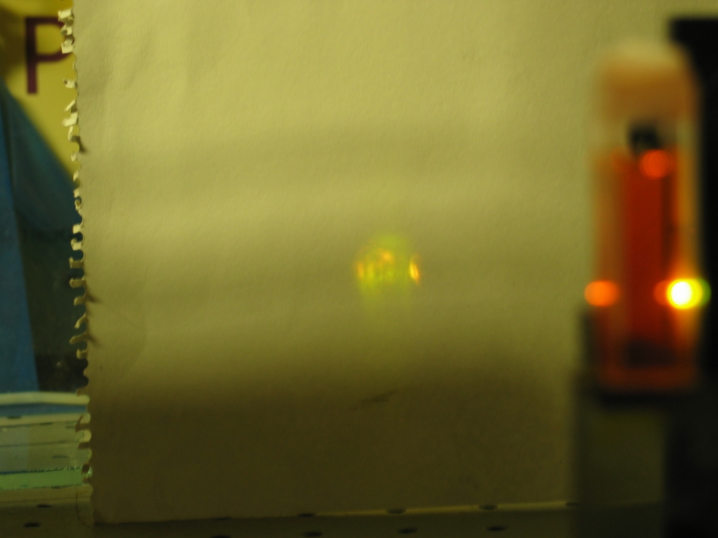
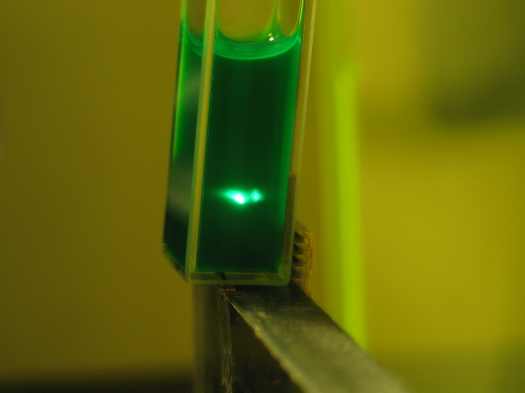
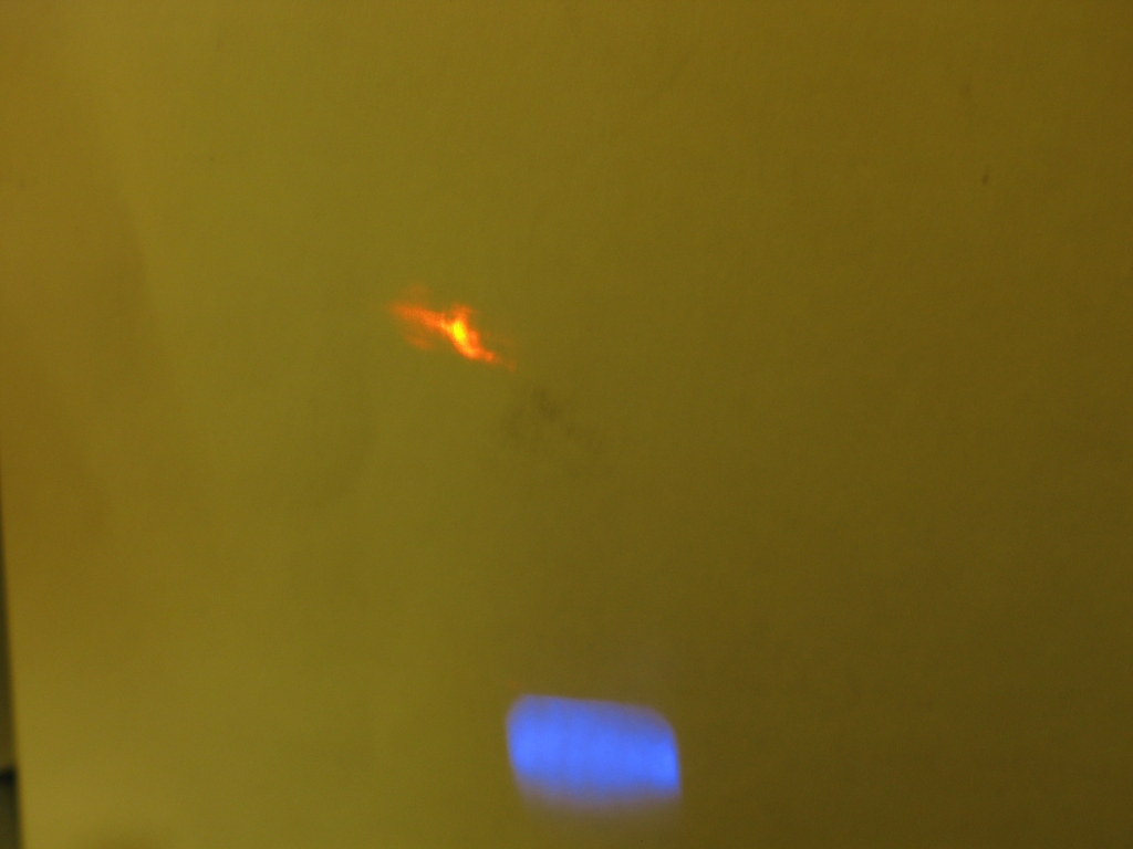
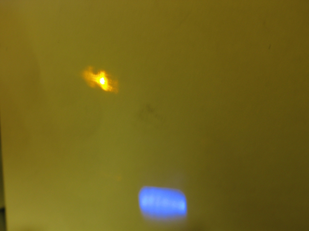
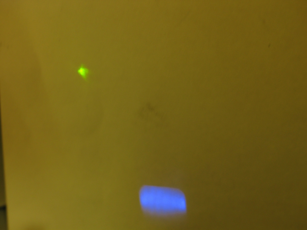
Here is a “photographic tuning curve” for the orange dye, which you can see in the cuvette. Notice that it lases surprisingly far into the green, and not very far at all toward the red. I am not sure why this should be; it certainly wasn’t what I expected.
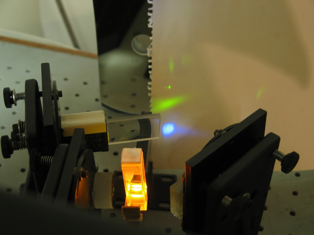
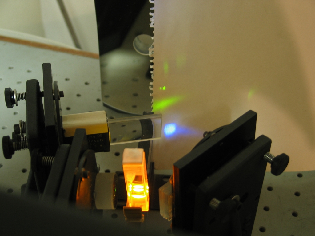
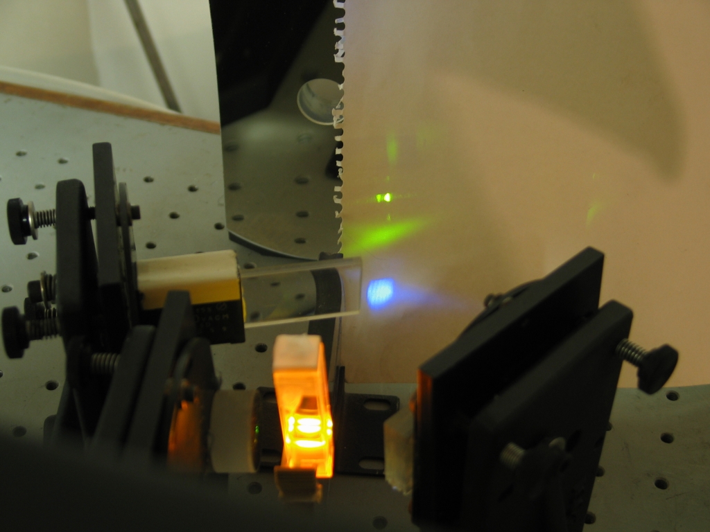
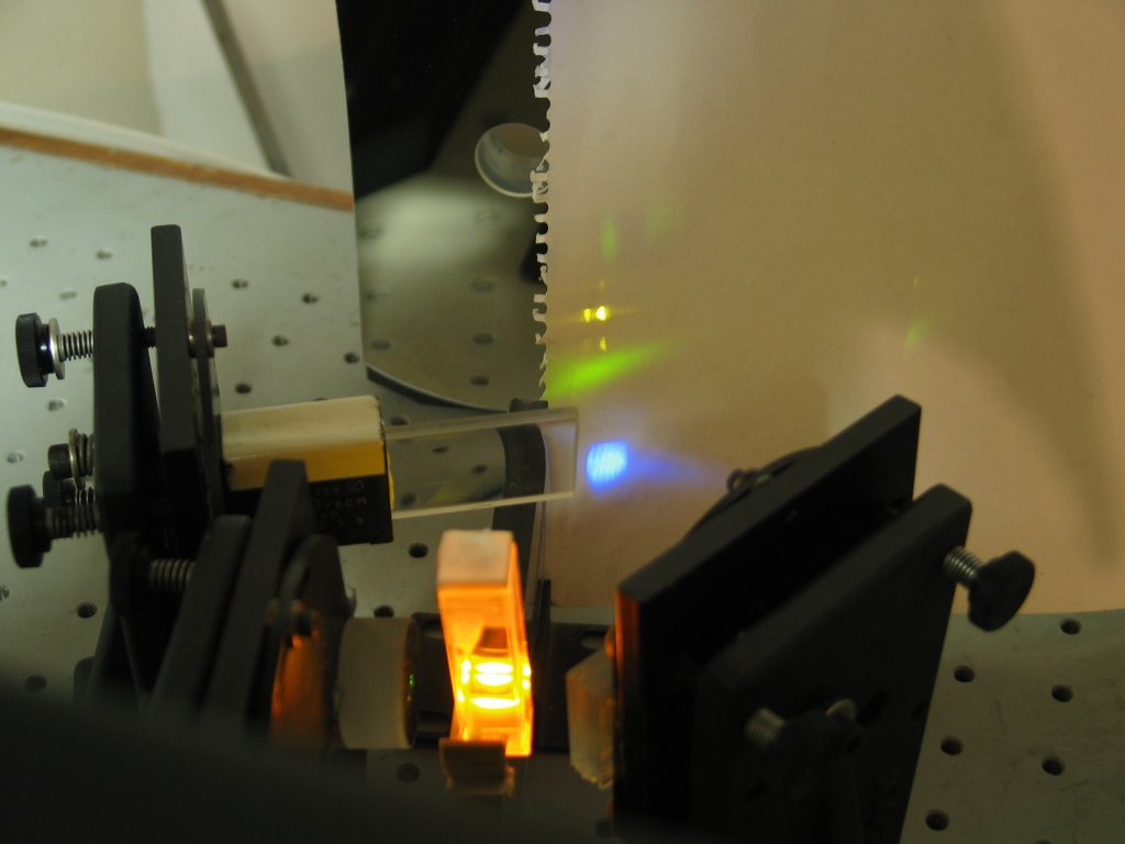
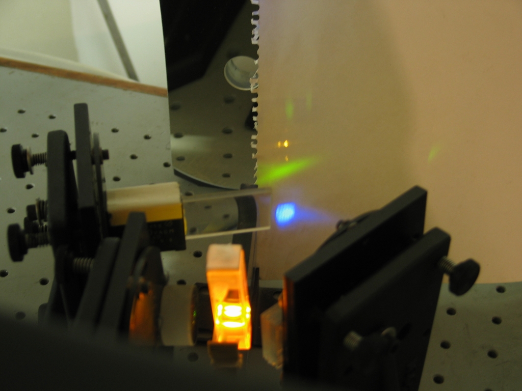
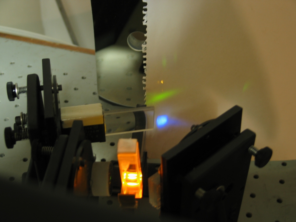
The diffuse green glow below the tuned spot is probably
superfluorescent lasing/ASE; the bright blue glow below
that is the paper fluorescing where a reflection of the
nitrogen laser beam is hitting it. The paper target is
leaning against the main focusing mirror; the
fused-silica cylindrical lens is between that mirror and
the cuvette. The flat mirror that forms one end of the
dye laser cavity is just barely to the left of the
cuvette, and the grating that tunes the dye laser is to
the right of the cuvette at an angle; it is just barely
visible at the left edge of the mirror mount that holds
it.
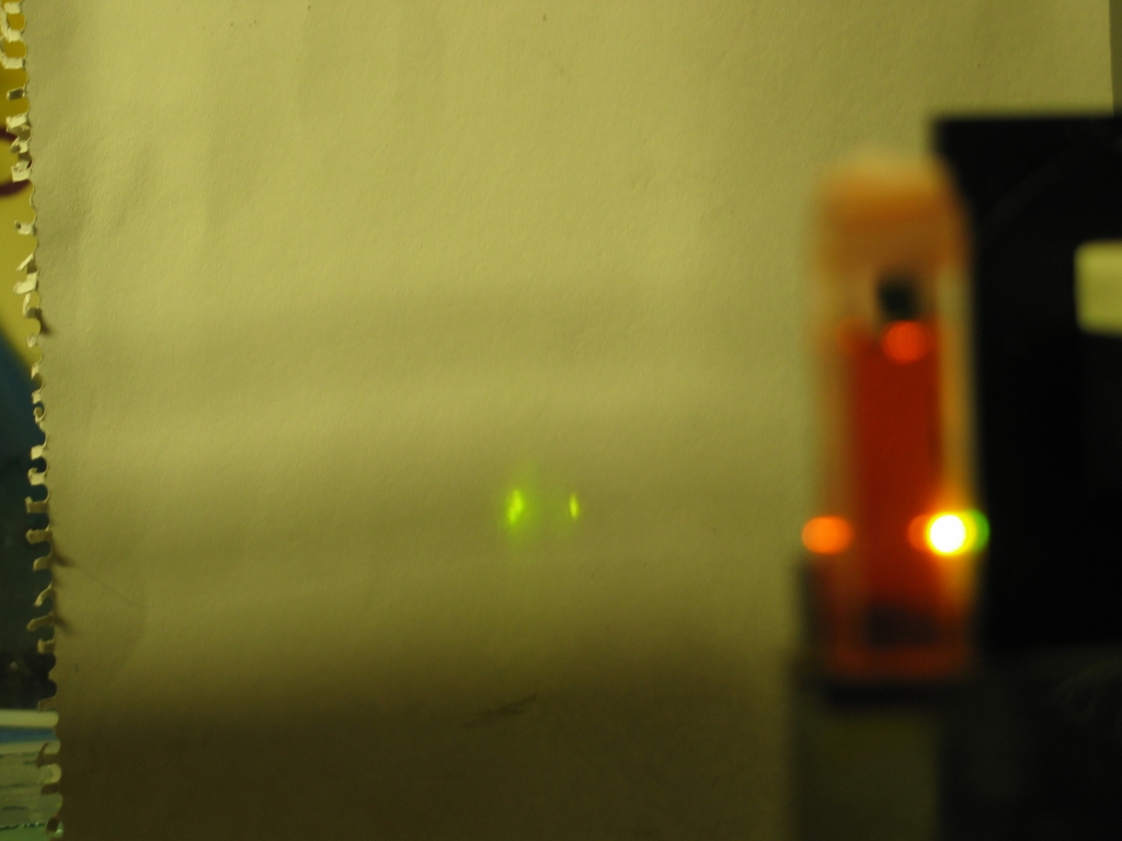
As of 20 April, I am extracting dye from another set of these markers, and if I can achieve lasing with the three remaining colors, I will present photos here. My early guess is that the red one may work, but I am not too hopeful about the green and blue ones.
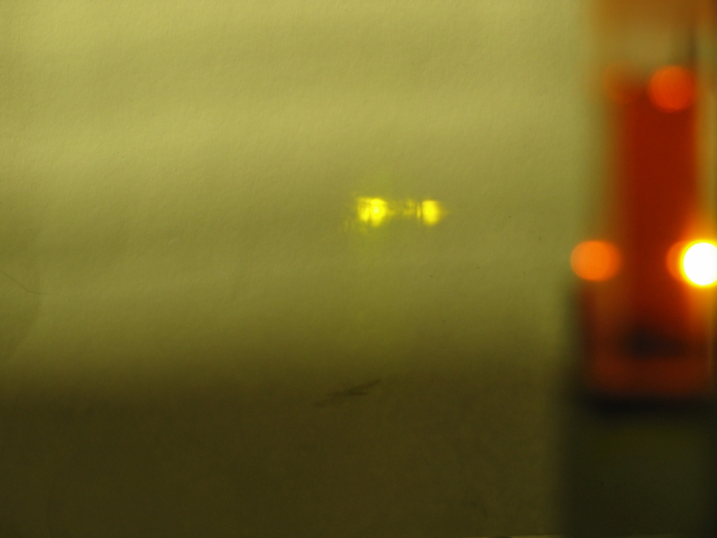
Indeed, I didn’t even try blue, as it had much visible color and very little fluorescence. I used green to take the photo of the beam shape, in the Alignment section, but was unable to get lasing from it. Red was a different story. It is not my idea of a good dye, as you can see from the “no mirrors” pictures in the Alignment section, but when I used the cylindrical lens to focus the pump beam down to a tight line on the front of the cuvette, I got some lasing from it, and was able to get a sense of the tuning range. Here is a very abbreviated “tuning curve”:
I have also tested a yellow-green “Hi-Lighter”,
which lased (but only moderately well), and I’ve
acquired some Bic markers but haven’t extracted
useful amounts of dye from them yet. I notice that my
newer set of Sharpie markers has two different blue
colors, neither of which appears to be quite identical
to the blue from the original set; the deeper blue has
no visible fluorescence, so I suspect that we can
ignore it for now. It may, however, fluoresce in the
far red or near-infrared, and I may revisit it later on.
(This is also true of the blue Foray marker.)
To the Joss Research Institute Website
To my current research homepage
My email address is a@b.com, where a is my first name (jon, only 3 letters, no “h”), and b is joss.
My phone number is +1 240 604 4495.
Last modified: Wed May 10 15:00:39 EDT 2017