(December 19, 2009, ff)
This page details the construction of a prototype dye laser that is intended for initial checking of some parameters — for example, I want to know whether a simple design will threshold “easy” dyes with minimal input energy. In principle, the answer is already known to be “Yes”; but in practice it may not be so easy. The laser will be operating close to margins, and any sacrifice of efficiency will be difficult to work around.
This preliminary design uses a commercial capacitor and a commercial spark gap switch, both of which I hope to eliminate in later designs. The machine that I’m working toward will almost certainly use a commercial flashlamp, though, because xenon is the most efficient emitter in the wavelength regions of interest for pumping organic dyes.
It will, very likely, also use commercial laser mirrors.
Quite a few dye lasers have been operated with simpler
mirrors, which could be homebrewed, but I am not at all
certain that these machines will have enough
“oomph” to overcome the losses inherent in
[e.g., aluminum] mirrors. OTOH, for those who are
willing to work at long wavelengths, using red and NIR
dyes, sputtered gold mirrors may be viable: a clean
coating of gold has reflectance of at least 98% from the
far red on out through the IR, and a thinly-sputtered
coating could serve as an output coupler.)
This laser uses high voltages, and capacitors that can store lethal amounts of energy. It puts out a laser beam that can damage your eyes and skin, and it uses organic dyes, some of which are known to be quite toxic. It also uses flammable organic solvents.
It is important to take adequate safety precautions and
use appropriate safety equipment with any laser; but it
is crucially important with lasers that involve
high voltages and present a health and/or fire hazard!
I have built a number of lamp-pumped organic dye lasers in the past, and I have read a number of articles about dye lasers in technical journals. In the course of doing so, I’ve noticed some characteristics that appear to define viability. Reasonably high optical pump power is required, and that is best obtained with a xenon-filled flashlamp. Xenon lamps can have efficiency as high as 50% or more under optimum circumstances. Granted, not all of the light can reach the dye solution, and not all of what reaches the dye solution can be absorbed by it; but those issues make xenon even more attractive as a source.
High pump power is also best obtained by driving the lamp with a short electrical pulse. This is one place where many DIYers go astray, by attempting to run their lasers with large capacitors at relatively low voltages. In order to create a short pulse you need to minimize both the inductance and the capacitance of the circuit that drives the flashlamp; operating at low voltage essentially makes that impossible.
Let’s run through a few numbers here so I can show you what I mean.
If you want to deliver 25 Joules to a flashlamp, and you are using photoflash capacitors that you charge to 400 Volts, you need 312.5 μf to store the energy. We can easily make a rough guess at how fast such a capacitor will discharge; ignoring resistive effects, the FWHM (Full Width at Half of the Maximum Amplitude) pulsewidth, in seconds, can be approximated as π times the square root of the product of the inductance and the capacitance, where the inductance (L) is in henries, and the capacitance (C) is in farads.
In an article on lamp-pumped dye lasers that was published some time ago, the authors determined that it is quite difficult to achieve system inductance of less than 125 nanohenry, so I am going to use 150 nh as the inductance value for this calculation. That’s optimistic; but it is consistent, and will do for now. (Just don’t expect an actual physical lamp driver circuit to meet the number predicted by this calculation; any real circuit probably has higher inductance unless it is extremely well designed, and in addition there are resistive effects that this calculation does not take into account.)
At 312.5 μf the expectable pulsewidth calculates to be about 21.5 microseconds, which corresponds to electrical power of about 1.16 MW. That may seem like a lot, but in fact it isn’t as much as we want. With actual photoflash or other electrolytic capacitors, which have high ESR and ESL (Effective Series Resistance; Effective Series Inductance), the discharge would probably be far slower, with correspondingly lower peak power, not even remotely close to what’s needed here. (Thanks to Jarrod Kinsey for bringing the ESR/ESL issue to my attention, and to Dr. Mark Csele and Dr. Winfield Hill for relevant information. Dr. Csele even has an oscilloscope trace on his Website, [right side, about ¼ of the way down] showing this problem directly.)
Now let’s try the same thing at 20,000 volts.
At 20 kV you need only about 125 nf to store the energy. The expectable pulsewidth is now just over 430 nsec, and the resulting electrical power is a little more than 58 MW. That is considerably more satisfactory. [Side note: if we guess that peak power occurs when the capacitor is at about 2/3 of its initial charging voltage, the peak current is a little over 4,000 Amperes (!).]
In terms of actual circuits, the situation is more extreme than I have presented it: photoflash and other low-voltage pulse capacitors are not designed to have low effective series inductance (ESL), so the system inductance will be larger than the amount I have used in the calculations. The use of wires to connect various parts of the circuit to each other also increases the inductance, slowing the discharge still further.
I trust that this explains my preference for high voltages,
in spite of the difficulties and occasional annoyances
involved in their use.
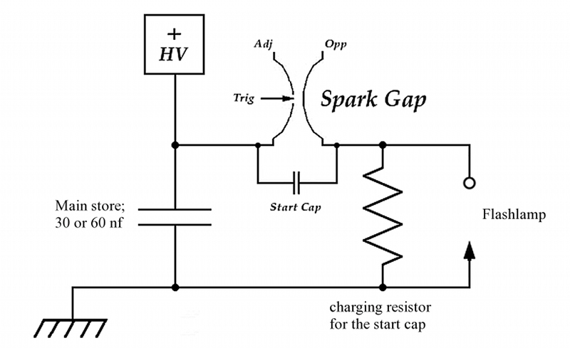
The circuit of this machine is quite simple: a capacitor is connected to the flashlamp by a spark gap, which serves as a switch. The other end of the flashlamp is connected to the other end of the capacitor, which is grounded. The one subtlety is that there is a small capacitor across the spark gap; it encourages the rapid formation of a good conduction channel when the gap is triggered. In order to be sure that this small cap gets recharged between pulses, the anode end of the flashlamp is connected to ground through a large-value (you want to use about 1 million ohms, or perhaps a bit more) high-voltage resistor. Here is a schematic diagram:
Wide pieces of brass shim stock are used for all of the high-current connections, to minimize inductance. (The shim stock I used for the initial build is too thin, but it seems to be working. Eventually I will probably replace it with thicker material.)
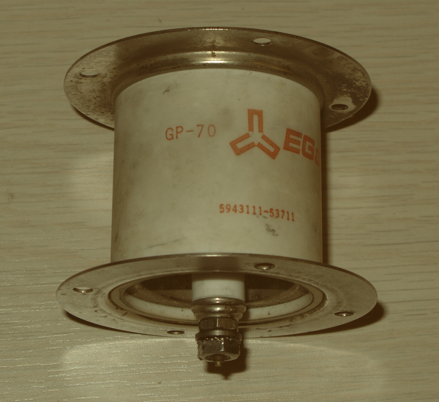
I am using a commercial spark gap here (an old EG&G GP-70), because I have one; I also have a trigger unit, which is handy. Both of these were acquired on eBay, so you could use similar items, but it is quite possible to build your own. Here is the spark gap:
The physical layout is determined by the relative shapes and sizes of the components, and by the need to avoid flashovers: we want the capacitor to discharge through the lamp, not around it.
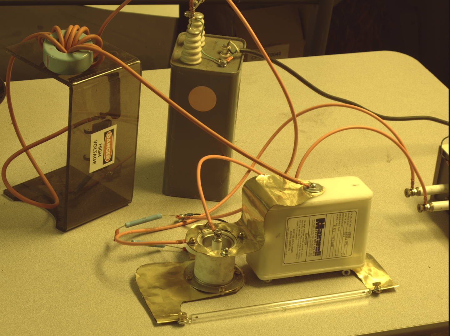
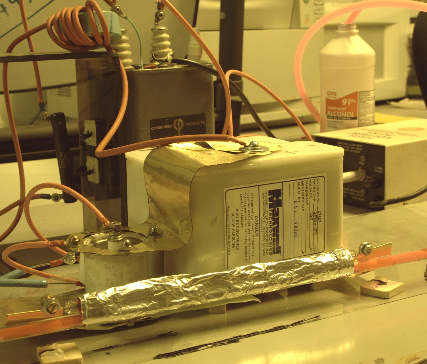
My choice of 25 Joules in the example in the previous section was not entirely arbitrary; that’s about the maximum energy that I use in another dye laser that I put together a few years ago. This machine, however, is more “bare-bones” than that; I anticipate using only 30 nf, which stores just 6 Joules at 20 kV. I have several reasons for this, one of which is that the particular capacitor I’m using is a type that is often available on eBay. It looks like this:
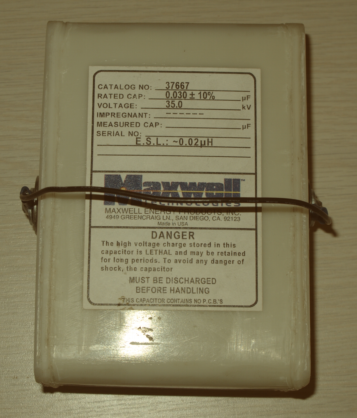
Notice that the capacitor itself contributes 20 nh to the system inductance. The ESL of the spark gap is probably within a factor of 2 of this, and my guess is that the flashlamp is even worse. (There are good reasons why it is extremely difficult to build a driver circuit that has less than 125 nh total inductance.)
If someone actually wants to build a laser to this design they should be able to, even though it is not what I am actually aiming for, and despite the fact that there are some reasons why I wouldn’t actually recommend it.
The flashlamp I intend to use, at least for initial testing, is a little over 9" long. As of this writing, it is available from The Electronic Goldmine.
As supplied, the lamp has a trigger wire wrapped around it. I have removed this wire, as I do not intend to trigger the lamp; I will, instead, be firing it by overvolting it as abruptly as I can. (This is a fairly common technique. It is not as good as simmering the lamp, but it’s considerably easier, and will do for now. If this design turns out to be viable, I may attempt to build a simmer circuit later.)
Unfortunately, the lamp is not designed for fast-pulse service; it has skinny little wires out the ends, which are not good for a low-inductance design. It also has one other key shortcoming: the vendor’s listing claims that it is made of some type of borosilicate glass, rather than fused silica. That means it probably doesn’t pass much mid- to short-wavelength UV. For pumping Rhodamine 6G and other dyes that emit at relatively long wavelengths this may not be a problem; but it is likely to prevent the laser from operating blue, indigo, and violet dyes. We will do the best we can with it, and we’ll see whether that’s good enough. If not, we can change over to a different lamp (and/or, if necessary, more stored energy — I have two of the 30-nf caps).
[NOTE, added later: This lamp is significantly
fragile. My first one suffered a few too many
flashovers, and ceased to work after perhaps a hundred
pulses. It is a good idea to provide a little extra
insulation at the ends of the lamp, to keep it isolated
from the ends of the dye cell; and it is a good idea to
keep the aluminum foil close-reflector as narrow as
convenient, even though that will lose you a little more
light out the ends than is fully optimal.]
(20 December, 2009, early am)
Here is a view of the lamp driver circuit with the components positioned but not assembled:
![]()
I still need to: make the holes that will allow me to connect two of the shims to the capacitor; bolt the parts together; add the little starting capacitor across the spark gap; add charging and bleeder resistors; and clamp the ends of the relevant shims to the wires of the flashlamp. At that point the driver circuit will be done, and I can test it. Assuming that it fires the lamp and does so without exploding it or turning it purple from too much short UV, I can then attach the dye cell and attempt to threshold Rhodamine 6G in isopropanol.
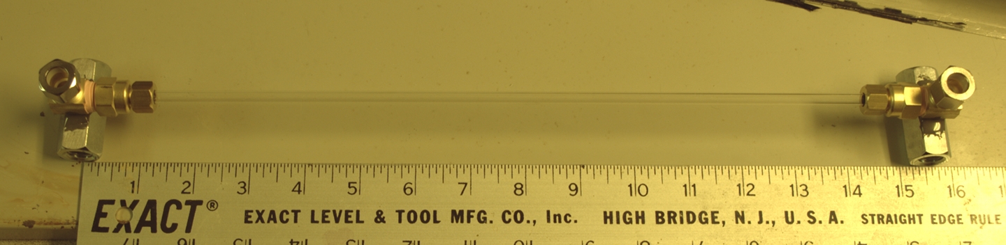
The dye cell should be relatively straightforward, but it will be much longer than it needs to be for this flashlamp. This is because I do not want to cut the tubing — I may need a longer piece in future, especially if this design fails to reach threshold.
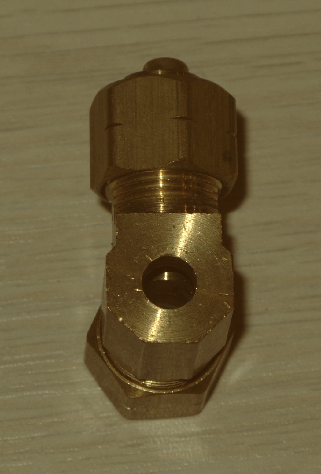
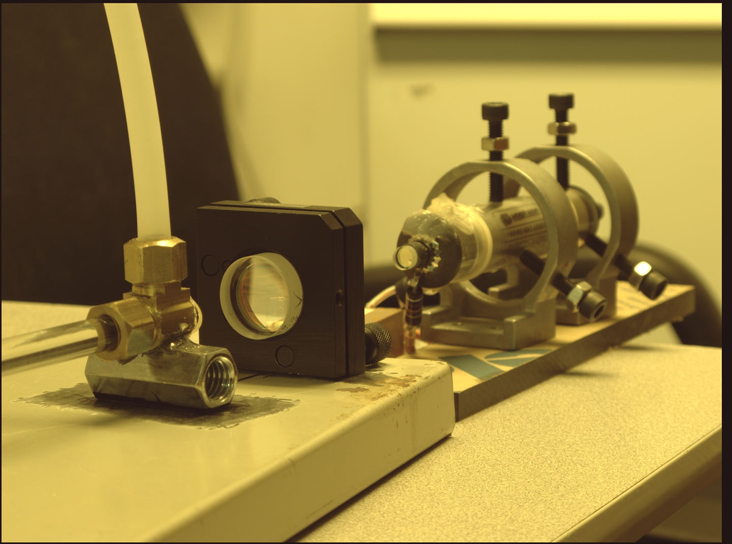
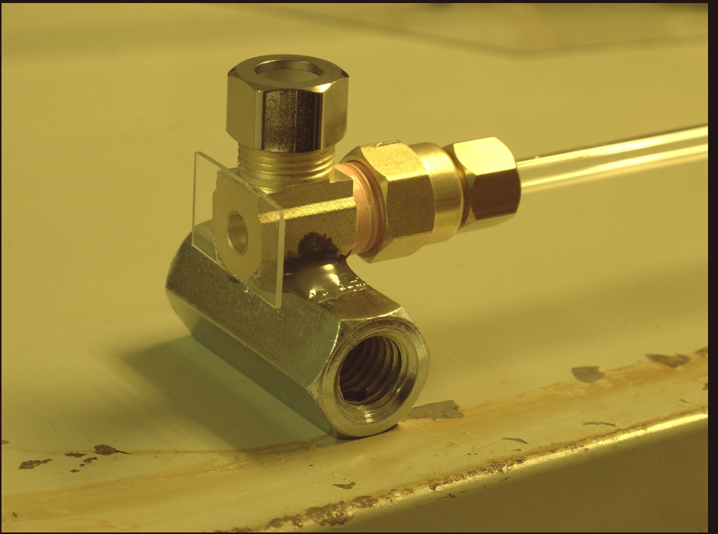
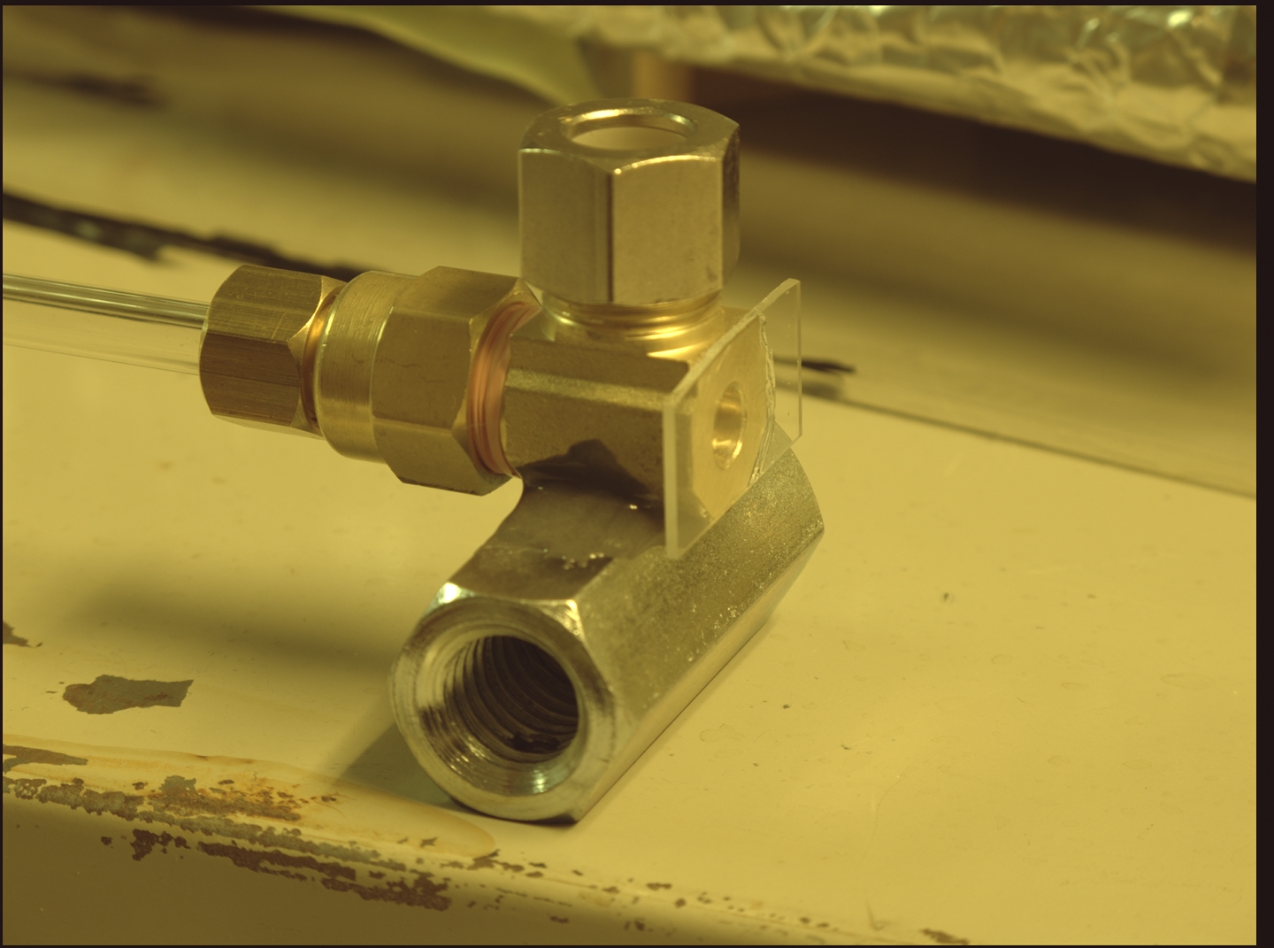
I am using compression fittings for the ends of the dye cell. They are convenient, and the tubing I have is a good fit. (I should note that I will be holding the dye cell tubing in with an o-ring, not with the usual parts, which are intended for use with either copper or polypropylene.) Here is a view of one of the fittings, with a hole drilled in it but without an end window:
(20 December, 2009, evening)
I am much closer now to having the lamp driver built and
testable. At this point I need to connect charging and
bleeder resistors, clamp the shims to the wires from the
flashlamp, and provide power and trigger. With some luck,
those things will occur later this evening.
(20 December, 2009, late evening)
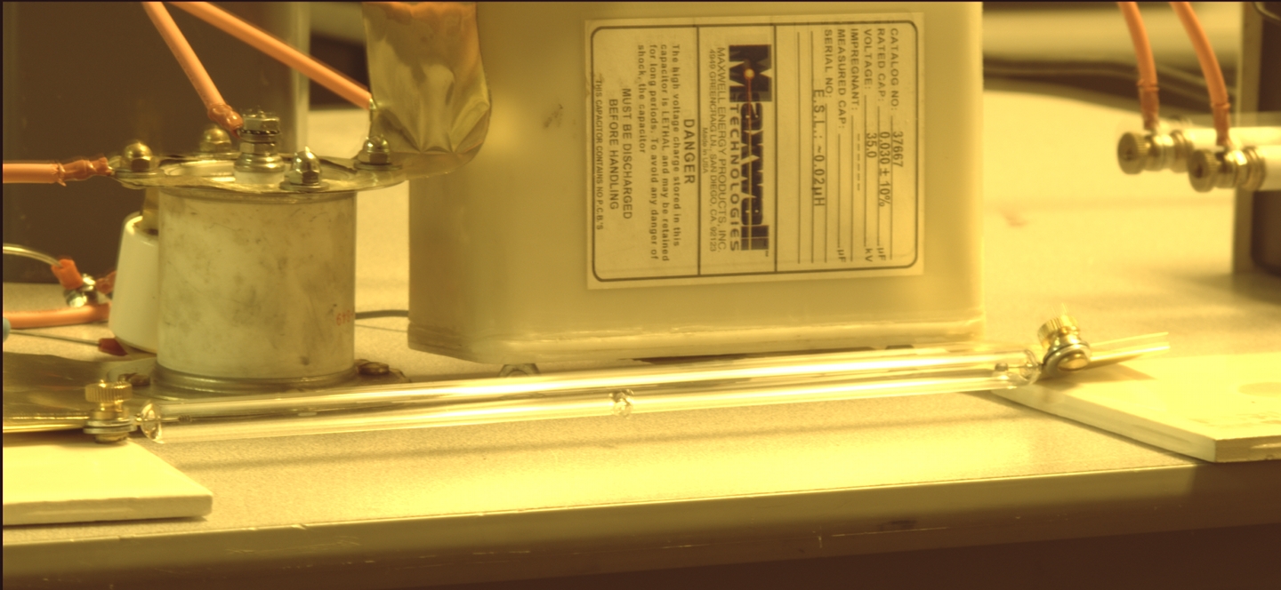
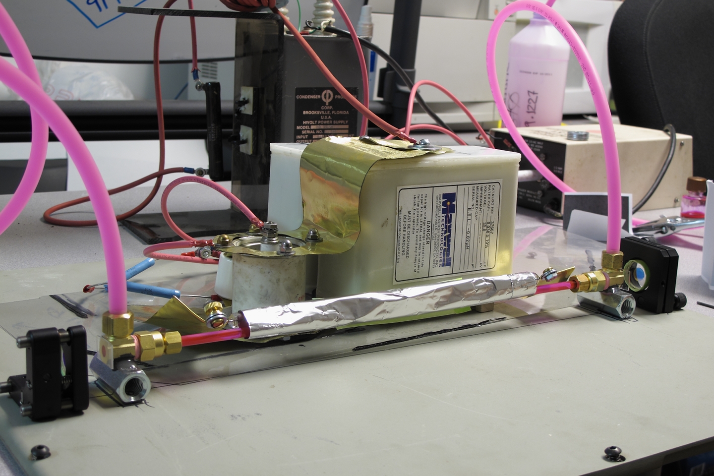
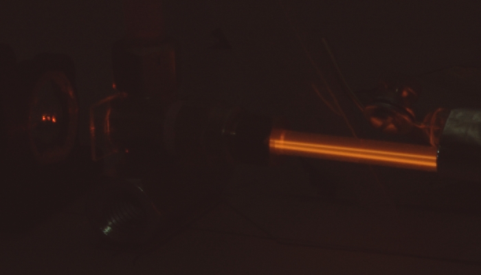
I ran the lamp at various voltages. It appeared to handle all of them reasonably well, which is a good sign. Here is a view of the lamp driver, set up on the bench for testing:
Here are two closer views, first showing the lamp cold, and then showing it being fired, with 18 kV on the capacitor. (The first view is blurred by camera motion; my apologies.)
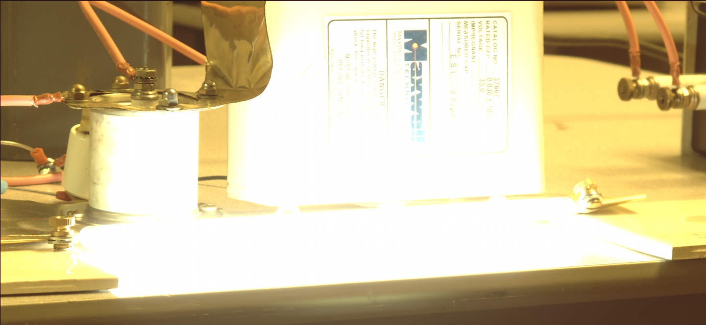
Although the flash is quite bright, I do not yet know whether it will prove to be bright enough. OTOH, at least I now know that the lamp handles as much energy as I initially intend to put into it.
(21 December, 2009, early evening)
The windows are mounted on the ends of the dye cell; I have the delrin rings and brass inserts I need for connecting the polypropylene tubing that the dye will flow through on its way to and from the cell; the cell ends are being attached to small mounting plates; I have a baseplate on which to mount the parts of the laser. I am now waiting for the epoxy to cure so I can mount the dye cell, set up and align the mirrors, and start testing.
(23 December, 2009, morning)
Two or things become clear to me after a certain amount of thought. First, I have mounted the dye cell ends incorrectly, and I need to fix that. I will be acquiring some half-inch aluminum bar. (Photo forthcoming later, after the new supports are in place.) I also want to bolt the mirror mounts to the baseplate, for stability, rather than simply attaching them with aquarium caulk. In order to do this, I will have to drill holes in the baseplate. Either way, I get to remove some of the paint.
I have also decided that the only source of cheap high-reflectance mirrors I currently know of is scrapped-out HeNe lasers. I even have several sets already on hand. These, unfortunately, are not broadband, so they limit the choice of dye to a very narrow range, but I have some Rhodamine 640, which should be a relatively good match, and will probably be the first dye I test with this laser unless I have some reason to try Rhodamine 6G or Fluorescein first. R640 may have one other advantage: it can probably be assisted by energy transfer from shorter-wavelength dyes, which would permit it to make use of more of the pump light. (This is actually true of various laser dyes, but the effect is only occasionally used. There can be complications under some circumstances, but I think I can avoid those by careful dye choice.)
(25 December, 2009, early afternoon)
After thinking about how to attach things to the baseplate, I decided to remove the small wooden plinths from the ends of the dye cell, and use something larger and metallic. Went to the hardware store to find some half-inch aluminum bar stock, and failed. Instead, I found some connectors for threaded stock. These look like very long hex nuts. I got a few, and eventually settled on the largest ones, which are intended for 7/16" thread. I sanded the irregularities off two faces of each, drilled and tapped two #8-32 holes in one of the faces, and glued the dye cell ends to the other face. Then I marked the baseplate, drilled holes, and bolted the dye cell down. This worked very nicely. I also drilled a hole for each of the mirror mounts, which worked fairly well except that for some reason I don’t quite understand, one of them is about 1/4" off to the side of where I want it. Still viable, though, at least for initial testing. (Photos of this progress are in the camera, and I will post them when I get a chance.)
Once I had everything in place I put a mirror at one end, shined a very small HeNe laser into the other end, aligned the HeNe with the dye cell, and aligned the mirror with the HeNe. Then I filled the dye cell with isopropyl alcohol, realigned the HeNe with the cell, and realigned the mirror. Then I put in the second mirror, aligned that, realigned the HeNe with the dye cell, and realigned both mirrors. (See the FAQ, below, for more information about this, with photos.)
At this point, all I need to do is wrap aluminum foil around the lamp and cell, fill the cell with dye solution, and start testing. It may take quite a few shots before I find the correct dye concentration, and I will probably need ot tweak the mirror alignment, but I am hoping to have a running laser some time this evening. (Fingers crossed; there is still no guarantee that this will actually work, and I may also have to swap out one or both mirrors — I was only able to find one HeNe mirror of a usable size; not sure where my other ones have wandered off to.)
(26 December, 2009, early AM)
I have not yet been successful in getting this thing to lase. I tried several obvious possibilities, none of which worked. My next move is to look for my other Maxwell 30-nf capacitor, and try 12 Joules instead of 6. Adding more capacitance is going to slow down the discharge, so I will get less than double the peak power, but I can still expect some improvement, and if the laser is only moderately below threshold, perhaps that will put it over the bar. OTOH, if there is some more fundamental flaw, adding another capacitor probably won’t help much.
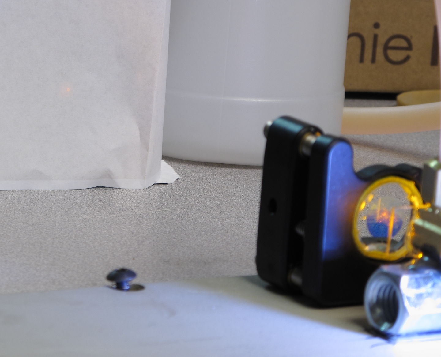
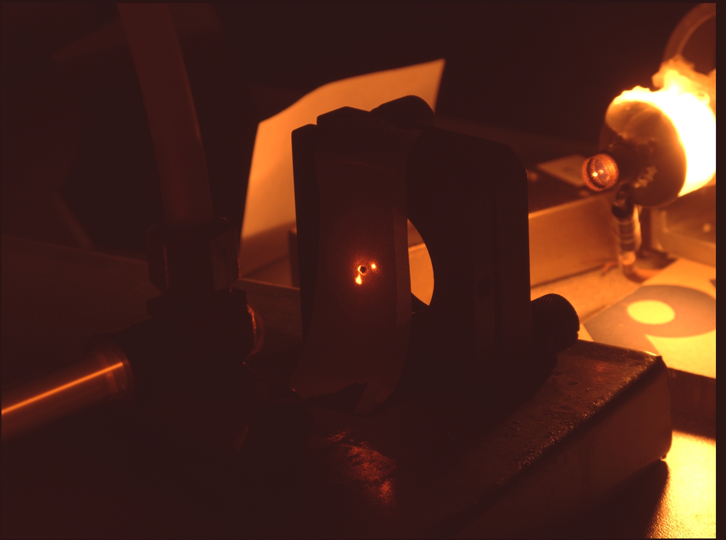
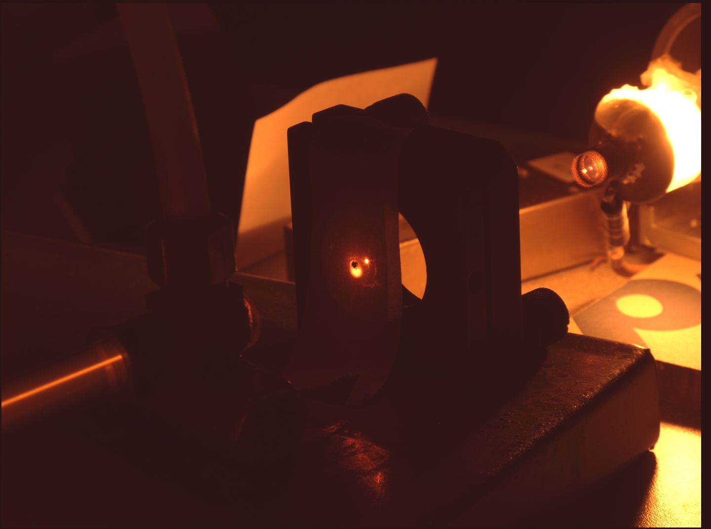
In the meanwhile, here are some photos. First, one of the ends of the dye cell, which was filled with plain 70% isopropanol at the time, and a mirror (it’s the HR from the back end of a dead HeNe laser). Then the other end, with a mirror and an alignment laser.

It is not easy to see in these photos, but the bore of the dye cell does not receive all of the light that hits the outside. Here is a photo that makes this easier to see:
(The tubing appears to be curved, but of course it actually isn’t. I took this photo with my iPhone and a small lens, which accounts for the distortion.)
(26 December, 2009, early afternoon)
I have added the second capacitor —
— but the laser still did not reach threshold. Later today I will switch to Rhodamine 6G, and we’ll see whether that behaves any better.
(27 December, 2009, early AM)
After some thought, I decided that instead of trying R6G
it would be a better idea to rebuild the dye cell...
(27 December, 2009, early AM)
Looking through my tubing stash, I found a piece that was just about the right diameter and length, and had a thin wall, so I built a new dye cell from it.
I looked for 1/4"-to-3/8" right-angle adapters, but didn’t find any, so I compromised by getting 3/8" compression to 1/4" MPT right-angle adapters and 1/4" compression to 1/4" FPT straight-through adapters. This is a bit more complex than I wanted to get, but I guess it will do. When I put the adapters together I used the thick pink teflon tape that is intended for waterpipes.
NOTE: If you build a dye cell of this sort, you will have to drill through the brass to provide a path for the dye laser beam. I drilled a small hole from the dye-cell side, because there was already an indentation left from the manufacture of the adapter that served in lieu of a centerpunch. I then turned the adapter around and enlarged the pilot hole from the other side, one or two drill sizes at a time, with the adapter firmly clamped.
I have run out of AR-coated windows for the moment, so I used small pieces of microscope slide instead; they are held on with silicone rubber aquarium caulk. Here are views of the ends:
You can see a tapped mounting hole in each of the “plinths”. It is about a quarter of an inch in from the end.
Because the glass or fused silica tubing is fragile, it is important to take the steps in the right order when you install a cell of this type. First, I will gently remove the tube. (It is present now so I can be sure that everything is in the correct position as I glue the ends to the plinths.) Then, holding onto the fittings (not the plinths), I will attach the polypropylene hoses that the dye runs through, and tighten the caps that hold them. Then I will mount one of the ends on the base. Then, with the fused silica tubing in place but held only loosely, I will bolt the other end into place. Finally, I will hand-tighten the caps that hold the tubing. This procedure worked well with the other cell, and I hope it will work with this one. [[Note, added the next afternoon: it did.]]
I have decided to swap out the baseplate, which I chose primarily because it was long enough for the initial dye cell. That is now out of the picture, and I have found a smaller plate that is much stiffer and will serve better. Here’s a photo, added the following day after I drilled the mounting holes in it:
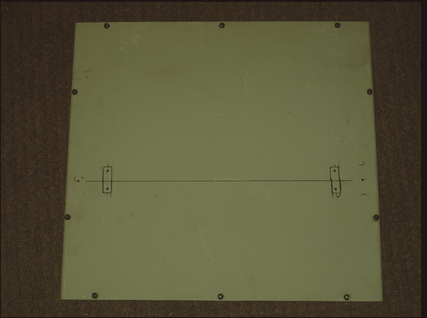
This plate is brushed aluminum, about 1/8" thick, and it has stiffening ribs on its underside. It is far more stable than the previous base.
I also found my old HeNe output coupler and put it in
the second mirror mount. There is some chance that I
could use it with its concave side toward the dye cell,
as I suspect that its radius of curvature is long
enough, but I think that for the moment I will leave it
with the AR-coated side facing the dye.
(27 December, 2009, afternoon)
Here is the laser on the bench, with the new dye cell in
place, ready to go...
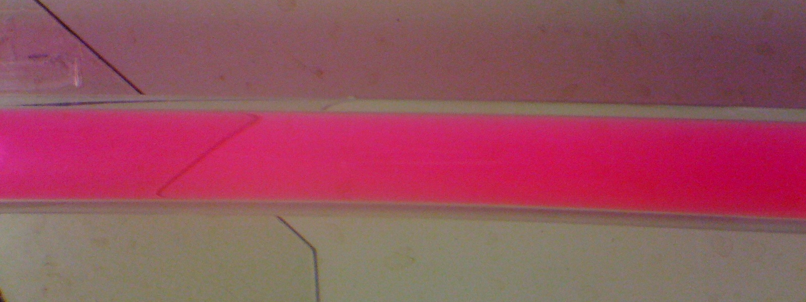
...and here it is, lasing Rhodamine 640 in 91% isopropanol:
The alignment is perhaps a bit sloppy, but I can deal with
that later.
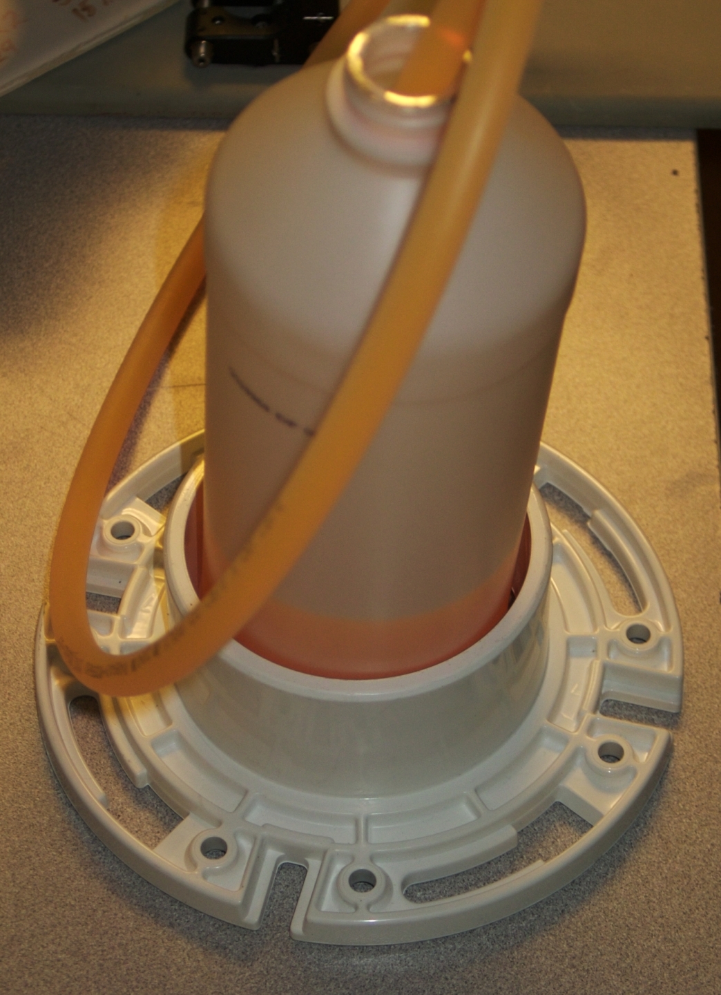
(A Helpful Hint, added some time later: If you
use the original bottles from the drugstore, as I often
do, you will find that when they are nearly empty they
have a tendency to tip over. You can easily prevent this
by going to the hardware store and buying two toilet
flanges of appropriate size. These are relatively
inexpensive, and they turn out to be quite handy for any
number of purposes; I have even used them as
telescope parts.)
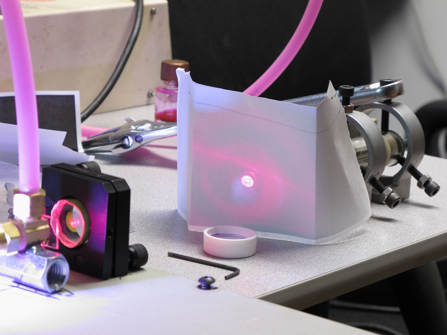
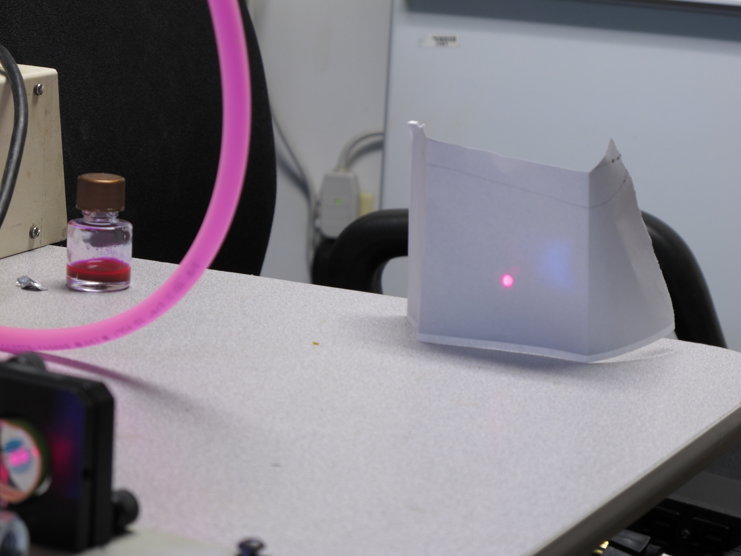
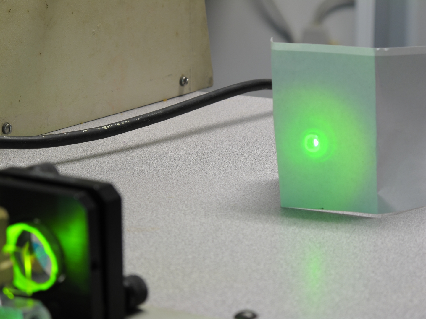
(Later that evening)
I disconnected the second capacitor, to see whether I
could threshold R640 with only 6 Joules into the
flashlamp. The simple answer is “Yes.” The
spot is not very bright, but the dye is definitely
lasing:
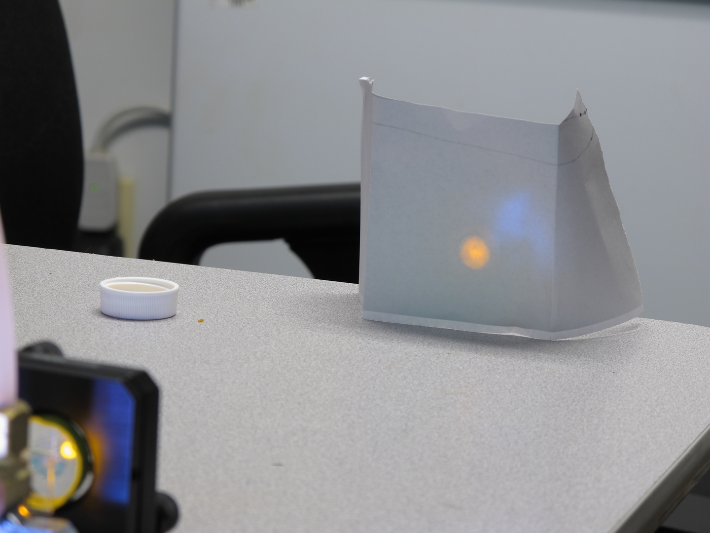
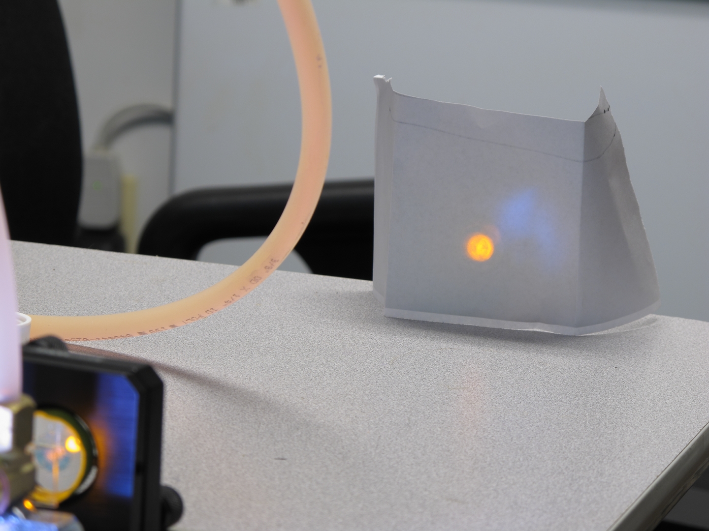
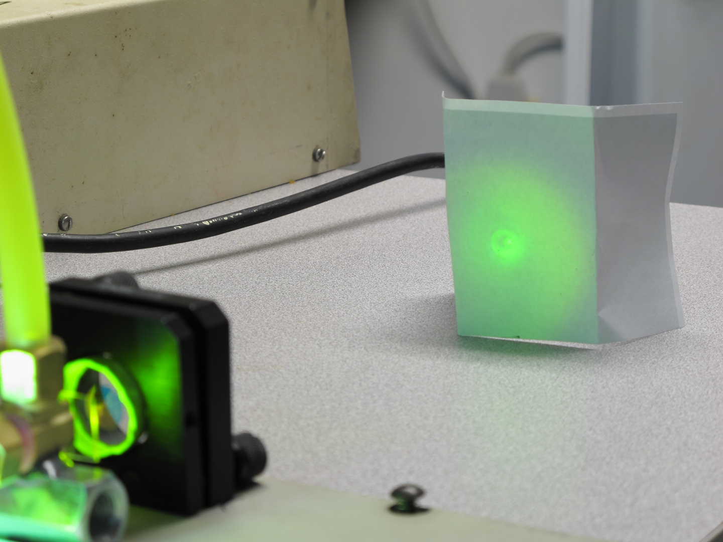
I then reconnected the second capacitor, rinsed out the
dye cell, and tried Rhodamine 6G in 91% isopropanol. My
R6G is of low purity, but it clearly works: even a
relatively dilute solution lased —
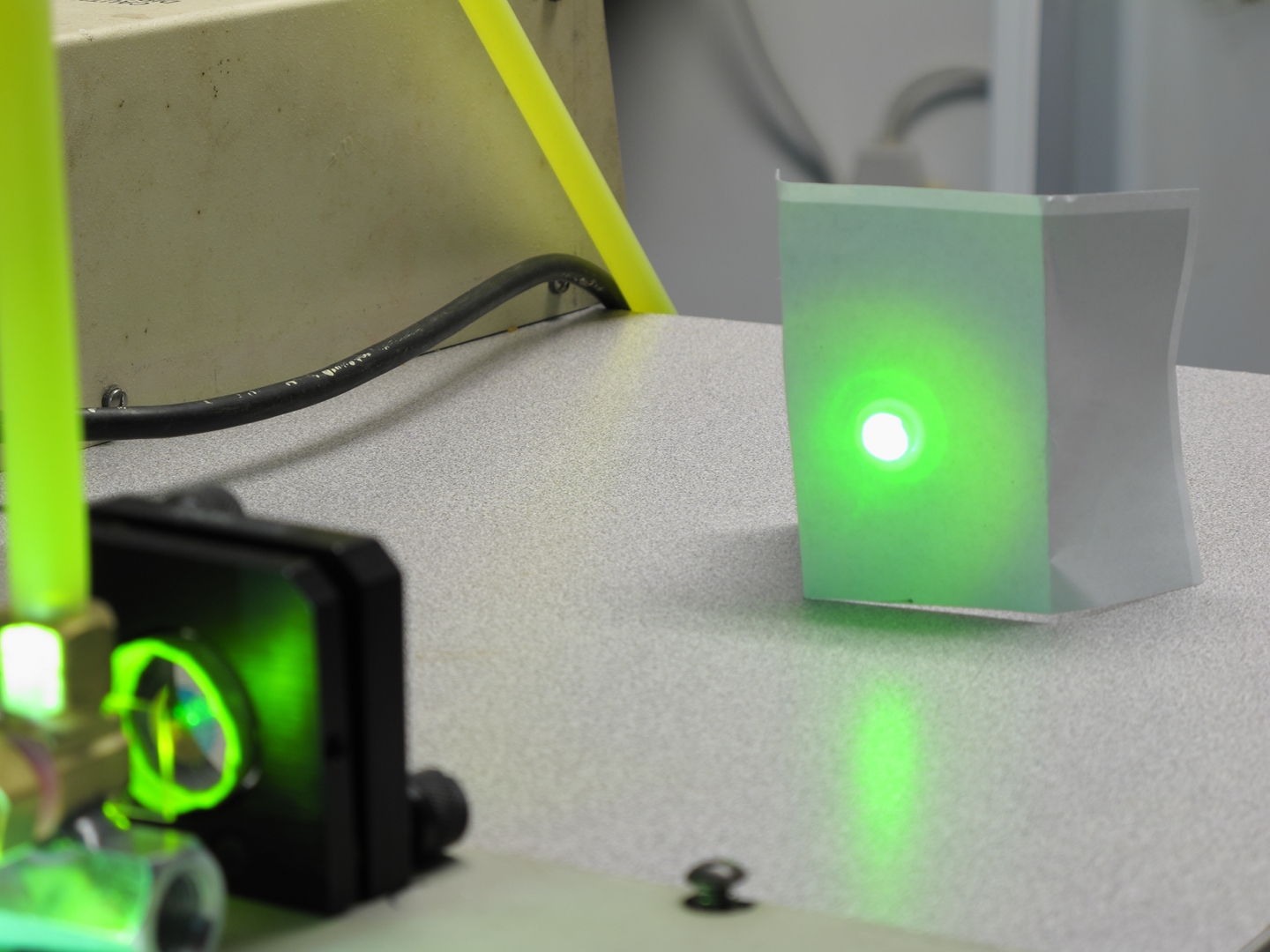
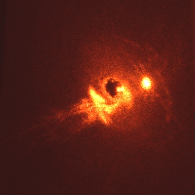
I added more R6G, and got a considerably brighter spot:
There was also a very small amount of output from the
opposite end of the laser. It was very difficult to
photograph, though, and is just visible here, slightly
less than ¼ of the way down from the top of the
image and a bit less than 1/6 of the way in from the
left edge...
(30 December, 2009, early AM)
Yesterday evening, as I mention above, the lamp ceased
to flash. Today I dug through my supplies and found a
very robust lamp that I am using until the new ones
I’ve ordered arrive from the Electronic Goldmine.
I am working toward thresholding some blue dyes, and
learning as I go. This evening I succeeded in lasing
Fluorescein in a solution that happened to include some
7-Diethylamino-4-Methyl Coumarin, though I have not yet
lased that in this laser. (Note, added 06 December: this
has changed; see below.) Oddly, I seemed to get much
better performance with the dye flowing toward the
output coupler than away from it; I am not yet sure what
could cause this.
Alignment was difficult. After I did as well as I
could with the HeNe, I was getting rather diffuse
lasing. In fact, it took several shots before I
really became convinced that there actually was
any lasing going on. I kept at it, though, and
eventually got a brighter spot. It seemed to be
slightly off to one side, so I started tweaking
the output coupler, a very small amount at a time.
Eventually I got this:
(Clear evidence that the alignment is off.)
Just so you should be aware of the cooling issue,
here’s what it looked like when I fired it
again before giving the dye enough time to flow
through the cell:
After a bit more tweaking, I got things lined up
fairly well...
I should note a few things here.
(05 January, 2009, evening)
(06 January, 2010)
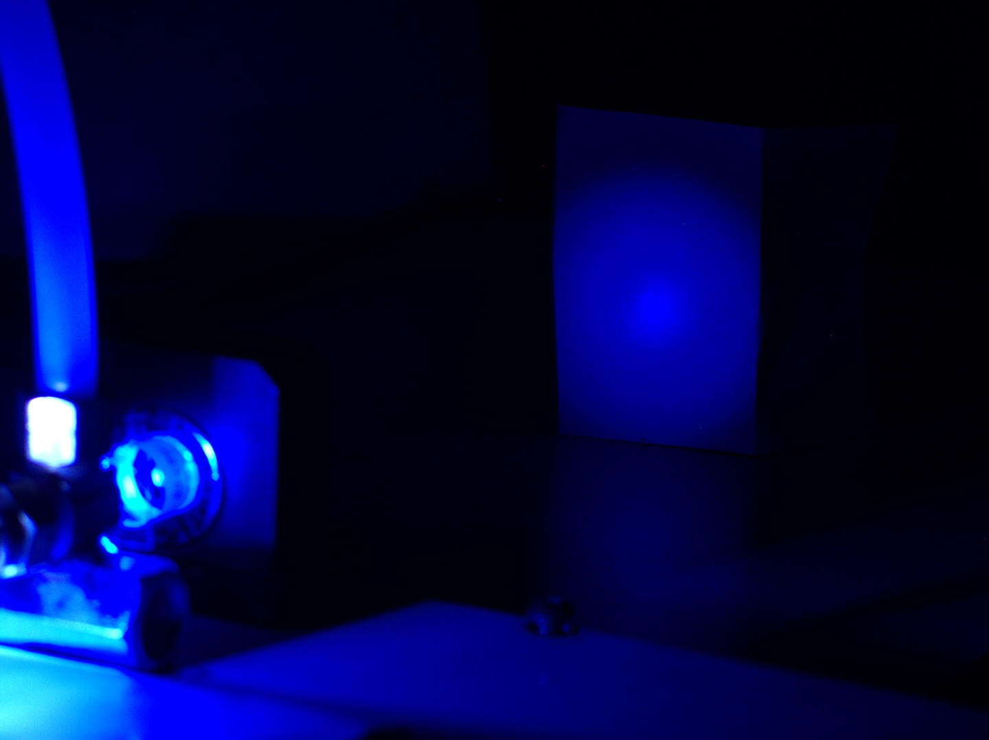
The next three photos show Dharma Trading Company
“Optic Whitener” in 70% isopropyl rubbing
alcohol from the drugstore. In the first photo, it is
not quite reaching threshold. (It tends to be very
frustrating to see that sort of pattern again and again,
but careful attention to detail can get you some
information even when the laser isn’t working the
way you want it to; if you ignore what you see in a
pattern like the one in the first photo, even though
there isn’t really very much to see, you
may miss something you need to know. On the other hand,
as
Yun Sothory
has pointed out in email, if you have not seen a
sequence of patterns like the three I show here, or at
least a good example of lasing, as in the third photo,
it can be very difficult to decide what a pattern like
the one in the first photo really means.)
The reasons why the laser failed to reach threshold are
not entirely obvious, but I suspect that the mirror
alignment was one of them. On the other hand, I have
seen it fail to lase when the mirror alignment probably
was good enough, so I suspect that other things are also
going on.
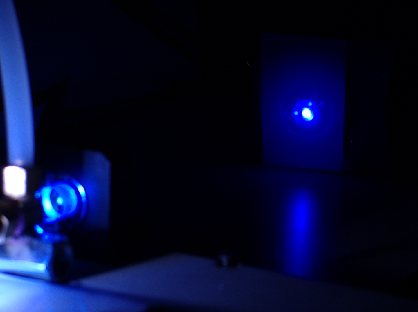
In the second photo, the dye is just barely
starting to reach threshold. You can see the blue area
in the middle beginning to get slightly brighter.
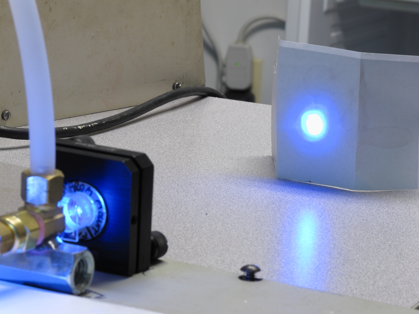
In the third photo, it is abundantly clear that the dye
is lasing. In fact, it is bright enough to cause all 3
colors in the sensor to max out. (That is, although the
bright spot appears to be white in the photo, it is
actually blue.) I am extremely pleased, because I have
wanted to lase this dye in a lamp-pumped dye laser ever
since I first found it, and because I was far from
certain whether 12 Joules would be enough to bring it to
threshold. In fact, until it lased and I took the photo,
I was not really sure whether it would lase at all in a
FLP dye laser. (This was the first time I’ve had
an opportunity to try it.) It’s a happy-making
thing to have a firm benchmark.
There are several reasons why blue/indigo/violet dyes
are more difficult to lase than dyes like Rhodamine
6G. For one thing, only a few of them have fluorescence
quantum efficiency as high as that of R6G. At least
equally important, however, is the fact that as the
wavelength gets shorter it inherently becomes more
difficult to threshold any laser. (This is a good part
of why it took so long to develop any X-ray lasers.)
I have not yet received another flashlamp from the
Electronic Goldmine, so I’m still using the more
robust lamp pictured above, which definitely has a
fused-silica envelope. Thus, I don’t know whether
this laser in its original state will be able to lase
any of the blue dyes. I should also mention the fact
that I am currently using a high-quality broadband
“Max Ref” flat mirror as the rear reflector,
and a helium-cadmium output coupler turned around
backwards as the output coupler; these are probably
about as good for ordinary blue dyes as HeNe mirrors are
for R6G, and almost as good as they are for R640. They
are considerably better than enhanced aluminum or
protected silver.
(Later that afternoon)
It turns out to be even easier to lase
7-Diethylamino-4-Methyl-Coumarin. Here it is in 91%
isopropyl alcohol, also acquired at the drugstore:
It looks to me like the mirrors are not aligned quite as
nicely as I would like, and I will probably tweak them
in an effort to improve the results a little.
I should perhaps point out that it is necessary to rinse
the dye cuvette quite thoroughly when you switch from
one dye to another. This is more important when you are
going from long wavelengths to shorter; for example, my
experience is that even a small amount of Rhodamine B
will effectively quench a solution of Fluorescein,
preventing it from lasing, while the Fluorescein output
photos above are from a mixture of
7-Diethylamino-4-Methyl-Coumarin and Fluorescein, which
lases quite happily. Not all such combinations, however,
will be successful.
(08 December, 2010, afternoon)
The replacement lamp has arrived, and I have installed
it. It does, indeed, appear to be borosilicate glass, as
advertised: I have been unable to threshold
7-Diethylamino-4-Methyl-Coumarin with it, which suggests
insufficient UV output. There is still some possibility,
though, that the problem is partly a matter of
pulsewidth rather than a lack of UV, and I will probably
have to make some measurements to see which issue is
more important.
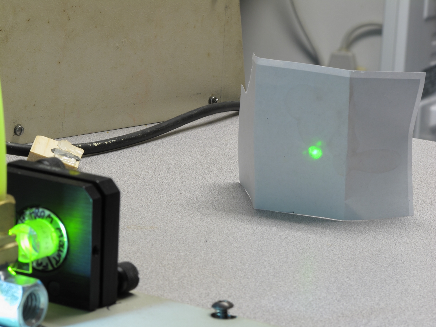
I added some Fluorescein to the dye solution and was
able to get that to lase. It was not as strong with this
lamp as it was with the more robust lamp, but there is a
different output coupler in the mirror mount now, which
may help account for the difference in output.
It is good to know that even with the relatively
inexpensive lamp this laser can provide green output.
(NOTE, added 08 January, 2010, evening: if you check
the absorption and emission spectra of Fluorescein
and
the absorption spectrum of Rhodamine 6G,
you will find that they are pleasantly compatible. This
fact led me to try them together, and I was not at all
surprised to find that adding some Fluorescein to a
solution of Rhodamine 6G enhances the output.)
(09 January, 2010)
It was suggested to me by Harald Noack, of Graz University
of Technology, that I simmer and prepulse the lamp. He
referred me to an article, which sounded very interesting.
I tried simmering, and found to my dismay that the laser
barely worked at all. In order to understand this, I took
some measurements of the light output from the flashlamp.
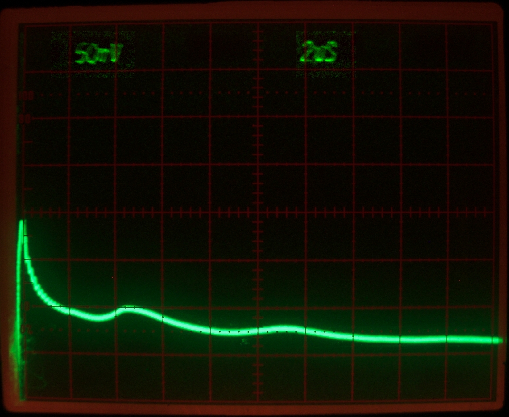
Here is an oscilloscope trace, showing the first obvious
problem:
At 2 μsec per division you can see at least three
peaks in the trace; my lamp driver circuit is
underdamped, and is ringing. This deprives the initial
pulse of some of the energy stored in the capacitor, and
thus decreases the peak power. I’m considering
what to do about this.
(I suspect, btw, that the sustained voltage between the
peaks is an artifact; it doesn’t seem likely to me
that the lamp would stay that brightly lit without much
current going through it. Harald Noack suggests,
however, that in fact the lamp does continue to
emit a substantial amount of light for some microseconds
after the end of an electrical pulse. It doesn’t
really matter; the real issue here is not what goes on
between the peaks, but the fact that there is more than
one.)
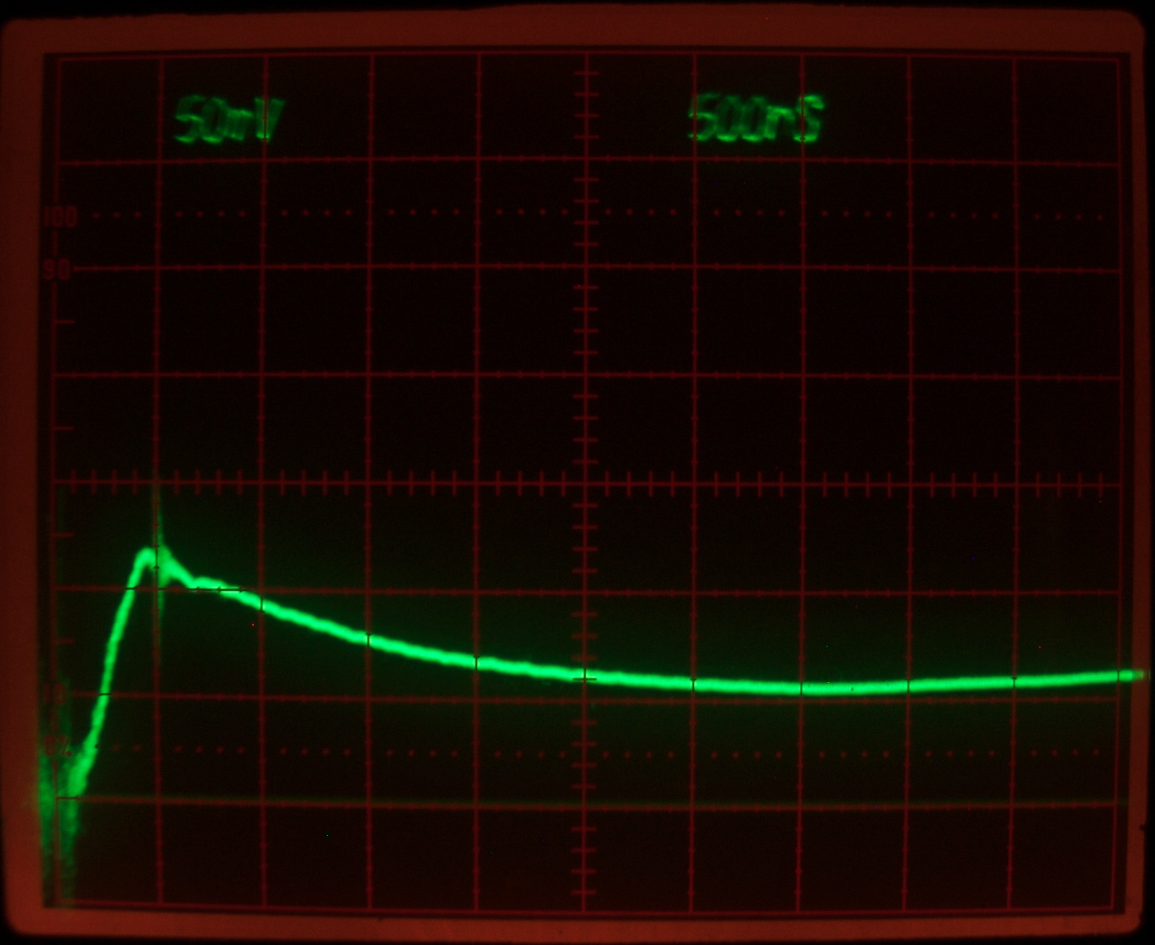
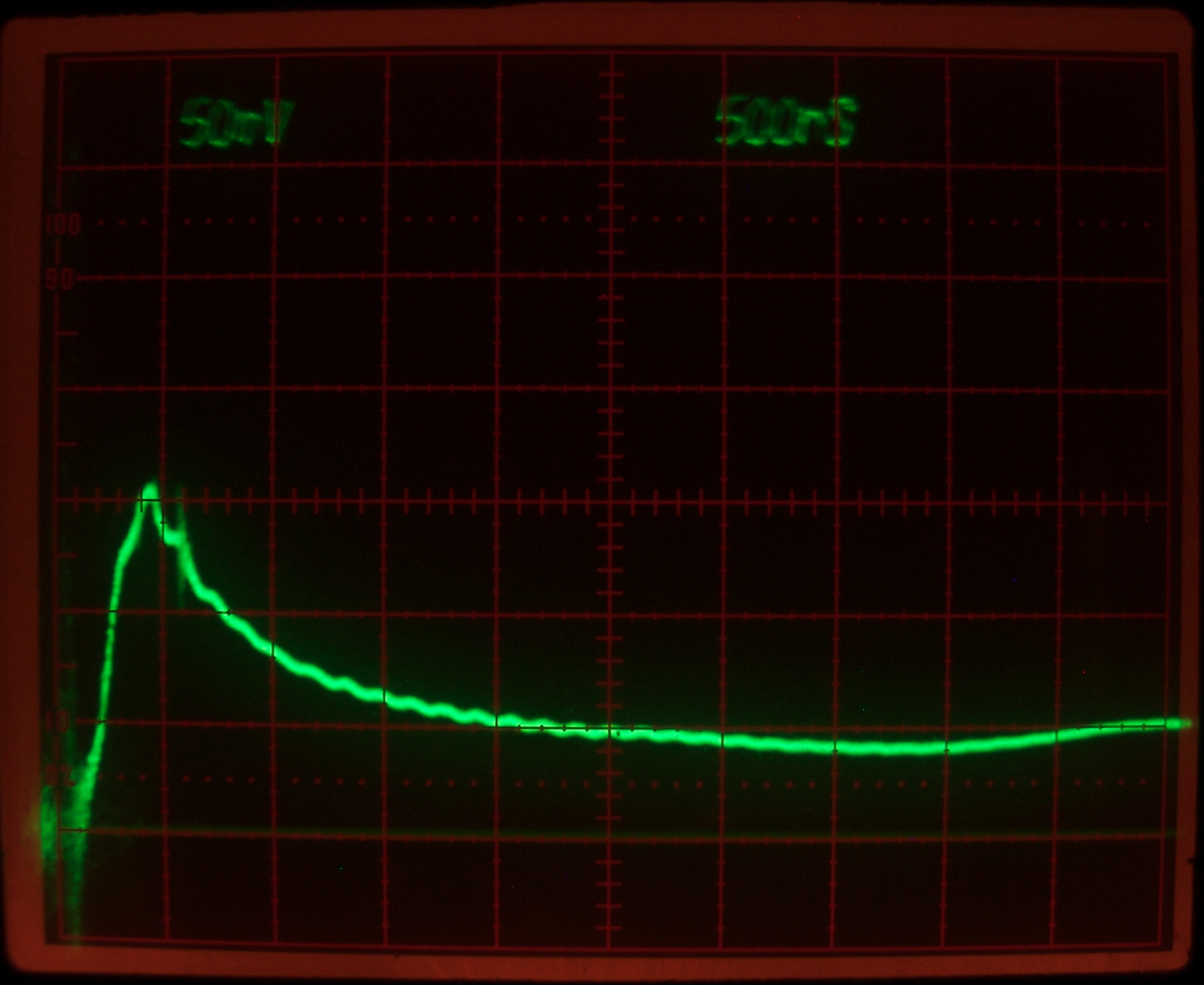
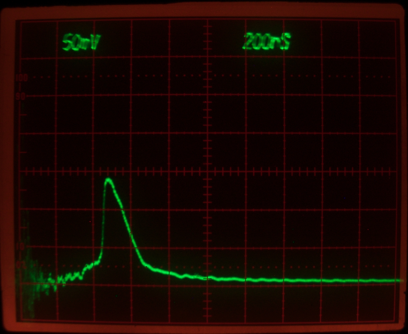
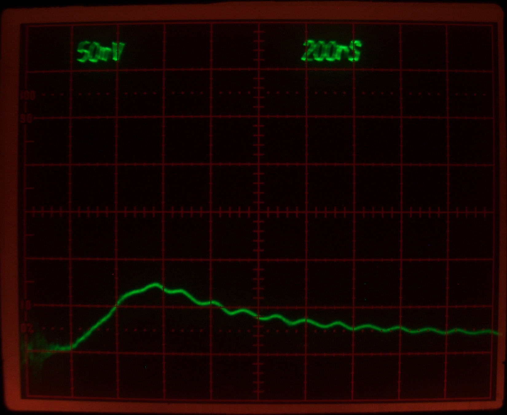
I also photographed traces with and without a simmering
current. These were taken at a faster sweep rate, and
mostly show the first peak. The polarity of the simmer
supply is negative, but the difference in performance is
not pronounced. Simmer on the left, no simmer on the
right. (In the photo on the right, the lower end of the
spark gap and its little starting capacitor are
connected to ground through a 400 K resistor. If I float
them, the performance is not as good.)
If you examine these carefully, you will notice that the
photo on the right has a slightly shorter risetime, and
a significantly higher peak. These differences are more
than enough to explain the fact that the laser barely
works at all when I simmer the lamp.
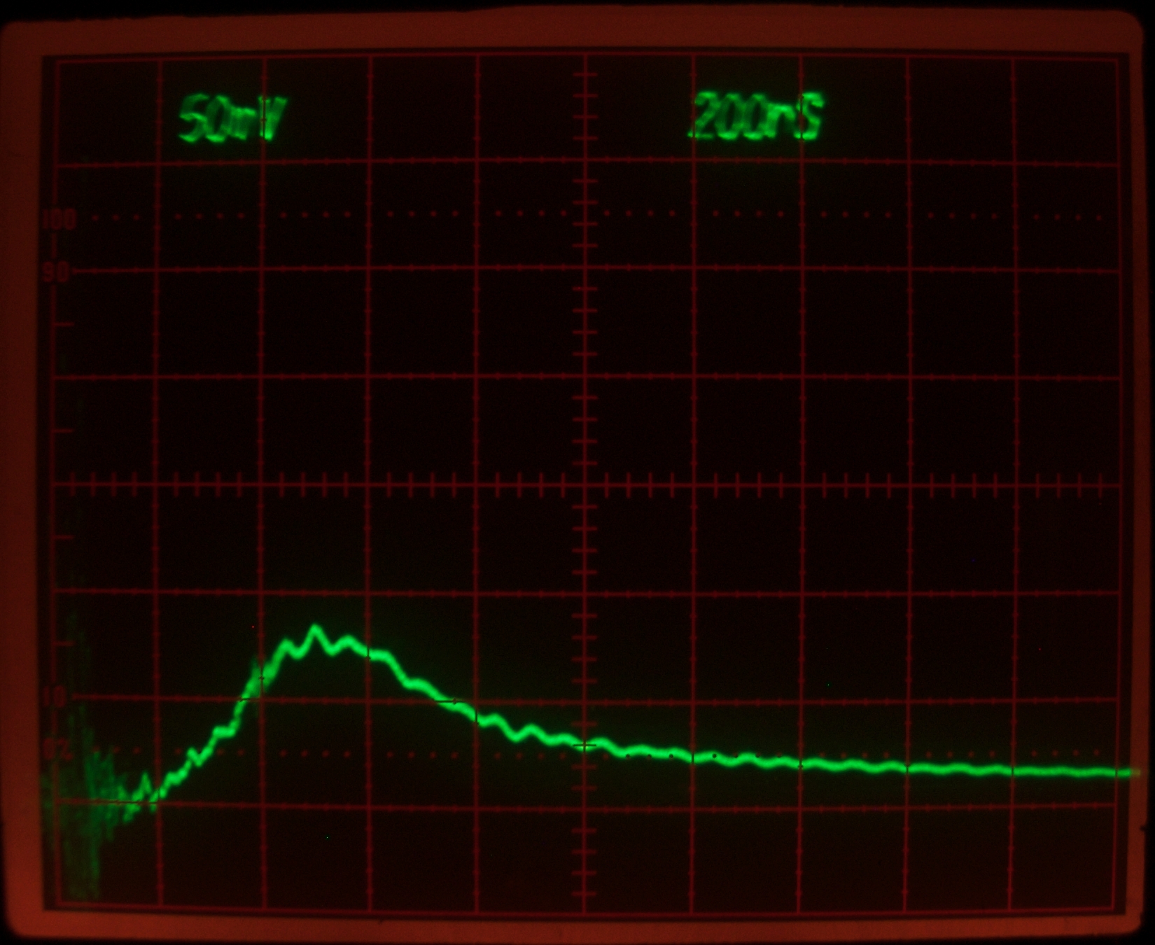
(Later that evening)
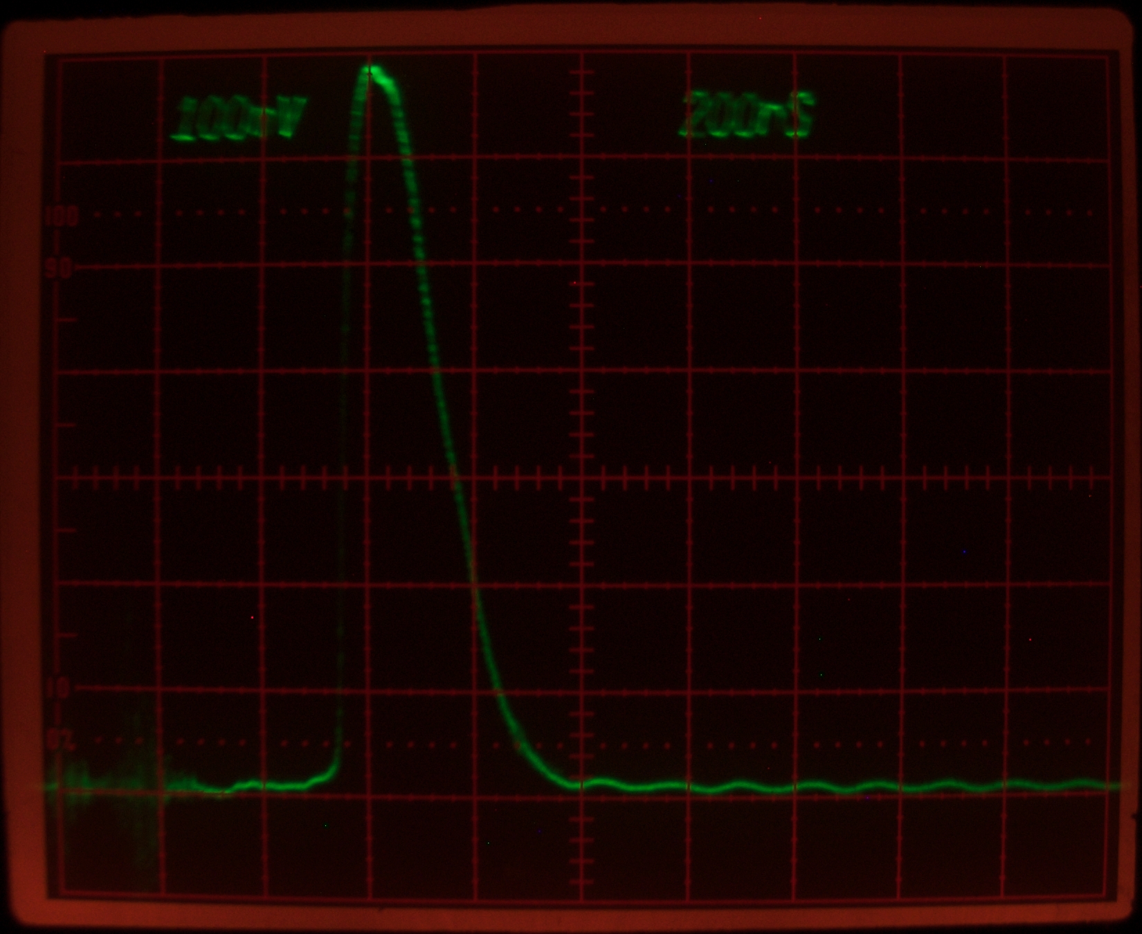
For the sake of comparison, I put the more robust lamp
(pictured above) back into the laser, and took two
scope traces. The first shows the lamp output with
the 400 K resistor to ground; for the second, I used
a piece of aluminum foil to reflect some R6G output
into the photodiode. It is probably instructive to note
the longer delay between the triggering event and
the beginning of the pulse, and the fact that the
pulse itself is narrower than the lamp pulse. Both
of these, of course, are entirely expectable.
The lamp pulse is single (I checked at slower sweep
rate) and more symmetric, with pulsewidth of 400 or 450
nsec, while the dye laser pulse has a fairly abrupt
risetime, begins near the peak of the lamp pulse, and
has pulsewidth of about 150 nsec in this photo, though I
have seen them as wide as perhaps 200 nsec. Both traces
shown here seem very reasonable to me.
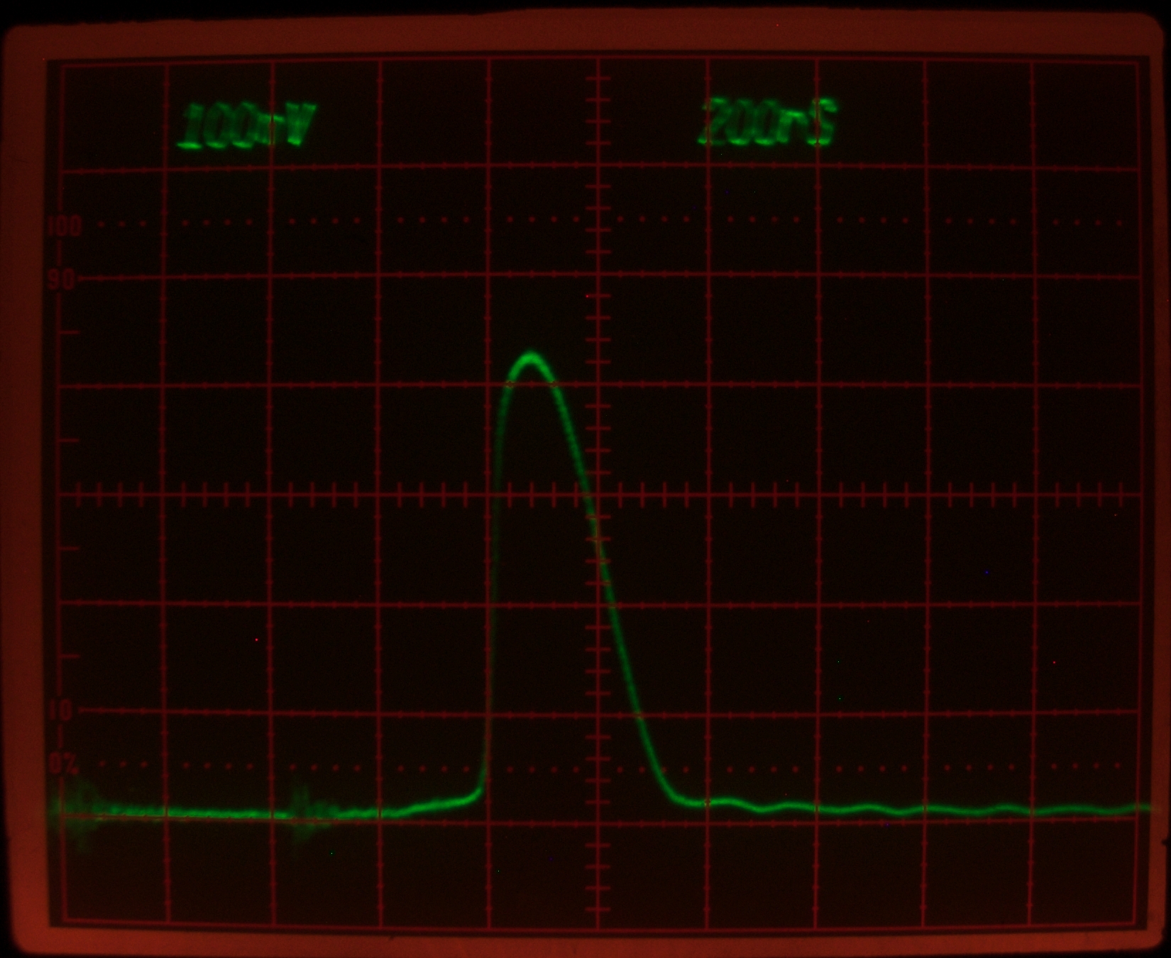
I then changed the simmer supply back to positive
polarity and connected it to the lamp. I found that I
had to use 800 K in series in order to get a sustained
discharge, and it became clear that this lamp does not
begin to conduct until the voltage across it is far
higher than was necessary with the other lamp. This very
strongly suggests that it has higher effective
impedance, and that fact alone may be enough to account
for the single pulse. Fortunately, the circuit does not
appear to be overdamped with this lamp in place. Even
so, simmering does not work well with it; here is a
scope trace:
This clearly shows a slightly longer risetime and a
noticeably wider pulse than the one just above, which
was taken without any simmer current. I still do not
understand why this should be the case, but it obviously
is.
I then took a look at the laser output, with and without
simmering. You will notice that even though I am just
using a piece of aluminum foil as a reflector to get
some of the laser light over to the detector, I have had
to cut the sensitivity of the vertical amplifier in half
because the lasing is significantly brighter with this
lamp than with the other one. (It is easy to see the
difference by eye when the beam is hitting the paper
target.) These two photos were taken in fairly quick
succession; the reflector and the photodiode probably
didn’t move between the exposures, so the vertical
scale should be close to the same in both. The one
above, however, was taken at a different time and with
things in different positions, so it is not directly
comparable.
Both of these are about 200 nsec or a bit more, FWHM.
The one without simmering is considerably brighter,
which goes hand in hand with the pulsewidth and peak
power. (Even if the difference in trace heights is
partly an artifact, it matches my visual observations.)
(11 January, 2010, evening)
NOTE: This project continues on
the next page,
as I am making some changes to the design of the lamp
driver.
(21 December, 2009)
Here are some questions that people may think to ask,
with some answers. Anything that does not have to do
specifically and exactly with this particular laser
is my opinion, and should be treated with mild
skepticism.
The errors and failures are your main pathways to a
deeper understanding of the issues you’re
facing. I present mine in the hope that they will help
you reach a deeper level of understanding more quickly.
To some extent they also expose my thought patterns and
my approaches to issues and problems, in case those are
of any interest or could in some way be helpful to you.
I built my first dye laser in 1970. At that time, I was
advised by some very savvy people that close-coupling
the lamp to the dye cell would probably work. They
also pointed out that wrapping aluminum foil around
things is very much easier than trying to make a precise
shape; that the interior of an elliptical reflector has
to be kept very clean; and that a large amount of light
escapes out the ends unless you use reflective end caps.
I thought about that, and used aluminum foil. It worked
just fine, and I have close-coupled every laser I’ve
built since then.
(I did try a diffuse reflector once, because it was
available; but that setup failed to threshold R6G. Then
I wrapped foil around the flashlamp and dye cell, and
the laser worked very well.)
This is best explained with a diagram. Until I have
a chance to make a proper one, I will use ASCII-pictures.
Here is a laser amplifier. (This is easier to explain
with amplifiers than with oscillators, but the principle
is exactly the same.) We will pump it with 28 units of
energy. I am going to specify that it is operating well
over threshold; let’s say it takes 4 units of pump
energy to bring it to threshold, so the remaining 24
units are available to produce amplification. This
particular laser is capable of amplifying by a factor of
10, so if the input is 1 unit of energy, the output is
10 units of energy...
[[Please remember that these numbers have nothing
to do with real life; I am just giving you an example
here. In fact, I am going to call the length of this
laser “five letters” to emphasize that
fact.]]
Now let’s double the length of the laser medium,
to 10 letters, without changing the amount of pump
energy. For clarity I am going to diagram this as two
lasers, each of which is pumped with 14 units of
energy. 4 of those units bring it to threshold, leaving
10 units to power the amplification...
Notice that each amplifier now has only 10 units of
available pump energy instead of 24, so it can only
amplify by 10/24 as much. (That’s really almost
4.2X, but let’s call it 4X for simplicity.) Even
so, we now get considerably more output. This will,
though, be true only if:
If the gain is saturated, more length adds to the output
arithmetically rather than geometrically, so you quickly
lose the advantage. With dye lasers (and with nitrogen
lasers) it is unusual to saturate the gain, so we
aren’t going to worry about that issue. Ordinarily,
all other things being equal, a longer active region
will reach threshold more easily and will give you more
output for a given amount of input energy, once you are
above threshold. (I use a flashlamp with 15 inch arclength
in my larger dye laser, and it works quite well at 20-25
Joules input energy.)
As Jarrod Kinsey points out, the tradeoff here is that
if you have a shorter lamp (and thus a shorter active
length of dye), you can compensate by using mirrors with
higher reflectance. There are two or three aspects to
that; the first is availability and price — can you
find mirrors with high reflectance, and are they
expensive? The second has to do with the output coupler:
if your OC is 99.5% reflective, you are not likely to
get much output from the laser. (If you just want to
know whether it has reached threshold, that probably
isn’t a problem for you.) The third has to do with
lamp life: a longer lamp, all other things being equal,
has a higher explosion energy. That isn’t likely
to be applicable to this laser, though, as we are not
putting much energy into the lamp. The bottom line, then,
is primarily the issue of whether you can find and
afford the mirrors you need.
I explain this above, in the text.
(In a sense, the specific voltage was chosen for me by
the fact that I have a small 20 kV power supply, the
fact that the capacitor is rated to handle up to 35 kV,
and the fact that the GP-70 spark gap works well at 20
kV.)
Broad connection paths help keep the inductance down,
which is necessary.
There is also another effect to bear in mind: with DC, a
thick wire can carry lots of current, which is what we
need to do here — you can figure that the peak
current in this laser is on the order of 4,000 Amperes,
as I mentioned above. With fast pulses, however, the
current travels in a thin layer at the surface of the
conductor. (Look up “skin effect”.) The
surface area of a cylindrical conductor goes up linearly
with the diameter, so it would take a very large
wire to carry that much current. It is much easier to
get large surface area with a piece of shim stock. (It
also lets me get better contact to the long thin wire
sticking out the end of the flashlamp, but in general I
avoid lamps of this type, so that’s a special
case.)
I should note that the shim stock I used in my initial
construction is actually somewhat too thin. I would
recommend 5 or 6 mils if you want to build a laser of
this type.
It is difficult to cut things at the correct angle
without a rotary table, which I do not have, and I
don’t need polarized output in any case, so I
punted this one. I wanted to use anti-reflection-coated
windows on the second dye cell, as I did on the first
one, but I didn’t have any more of that type on
hand, so I cut pieces from a water-white microscope
slide and used those. They are far from optimal, but I
guess they’ll do for starters. (I have some
AR-coated windows on order, and I may use a pair to
replace the pieces of microscope slide at some point.)
If I decide, in the future, that I want or need
polarized output, I will put a Brewster plate in the
cavity. That’s considerably easier than trying to
find a way to mount the dye cell end windows at
Brewster’s angle.
If you look at how an ordinary HeNe laser works, you
will notice that the rear reflector is flat, and is
at the center of curvature of the output coupler.
This is a stable configuration, and fairly easy to
align, but the active region is roughly conical. That,
in turn, means that some of the excited lasing medium
is not actually part of the laser, and any energy
that goes into it is wasted.
Moreover, it requires that the distance between the
mirrors has to be set fairly precisely. If they are too
far apart, only a much more narrow “cone” of
medium can lase. If they are too close together the
mode structure probably suffers, though that’s not
likely with a dye laser of even modest size unless the
mirrors came from a really long HeNe.
I usually turn the OC around backwards because I want to
use a larger proportion of the active material, and I
also do it when the radius of curvature is too short for
the distance between the mirrors.
The outer surface of an ordinary OC is curved so as to
allow the laser to produce a clean Gaussian beam. If you
turn it around backwards so that it faces the active
region it should act almost like a flat mirror [at
least, at the right wavelength], and it may be very
slightly easier to align. True, there is a small amount
of reflection, but the surface is always AR-coated, so
this is not usually an issue.
There are unstable cavity designs that are more
efficient because they use a larger percentage of the
excited medium, but I don’t have appropriate
mirrors to construct such cavities at visible
wavelengths.
If you have never built one of these things, you may not
have thought through the process of aligning the mirrors;
it is unavoidably tweaky.
Let me give you a runthrough. I hope that will make it
easier for you to see why I had to jump through so many
hoops, and I also hope it will make it easier for you
to do when the time comes.
First things first: you have to make sure that the path
through the laser is unobstructed, and you need to
choose an alignment tool that will work well. I use
small CW lasers for this. If your alignment laser
happens to be at a wavelength that is not reflected well
by one or both mirrors you will probably have a hard
time doing the alignment; likewise, if it is reflected
too well by the mirror that is closer to it, you
will have a hard time seeing the return from the mirror
that is at the far end of the dye cell. I have several
things I can use for performing alignments: a cheap
green laser pointer, a variety of little HeNe lasers, a
cheap red laser pointer or two, and a small violet diode
laser. (I haven’t needed the violet diode for
aligning anything yet, but it is handy anyway —
I use it to check things for fluorescence.)
It is also possible to use a borescope. A
straightforward design is shown, IIRC, in the
Scientific American “Amateur
Scientist” column on either the homebrew HeNe
laser, the homebrew argon laser, or both. I think it
uses a small incandescent bulb, for which you could
easily substitute an LED, as its light source; a
microscope cover slip as a beamsplitter; an eyepiece
from a microscope; and possibly one or two other
lenses. If you decide to use a borescope, that column
has good directions, so the rest of this discussion will
cover the use of a laser.
One suggestion for your alignment laser: make a paper
target with a small hole in its center. (I like to print
some convenient pattern of narrow lines on it, either
vertical and horizontal bars, a series of rings around
the hole, or both.) Tape or glue this target to the
front of the alignment laser, positioned so that the
beam emerges through the hole. The return is easy to see
on the paper, and the lines or rings can make it
slightly easier to figure out what is happening as you
make adjustments. If you do not have such a target it is
hard to tell where the return is and what it looks like,
and that makes it much more difficult to achieve
alignment.
Once you have a viable alignment laser:
I find it convenient to put a paper target at the far
end of the dye cell, so I can see what the beam looks
like as it emerges. The patterns are extremely
confusing, and it will take you a while to begin to
understand them, but once you have an idea of what you
are looking at it becomes somewhat easier to tell when
your alignment beam is actually coming through the
middle of the cell, and not bouncing off the walls on
the way.
If you darken the room, it is easier to see reflections
from the walls of the cell, and you can “walk”
the beam down the wall to the far end by making tiny
changes in the position of the alignment laser or by
moving the laser that you are aligning. My personal
experience is that this is about the easiest way to get
it lined up. For one thing, it is easy to tell if the
alignment laser is aimed slightly up or down, because
the beam will hit higher or lower on the wall of the
dye cell as you walk it along. Depending on the dye
and the wavelength of your alignment laser, you may be
able to see the beam inside the cell, even where it
isn’t hitting the wall. This can be extremely
helpful.
If you have followed that description, you will begin
to realize just how involved it is. In fact, I would
hazard a guess that some people have been unable to
get their dye lasers to work because their mirrors
were misaligned, rather than from any lack of pump
power/energy.
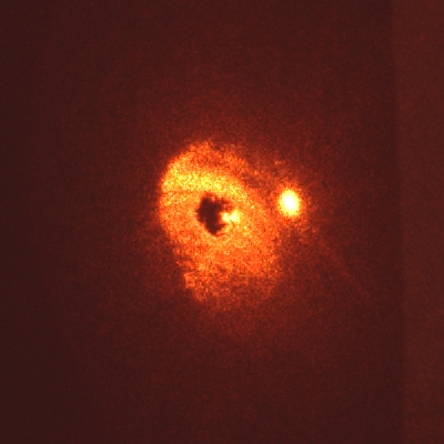
Here is a set of photos, taken very late in the
process. The first one shows what the target looks like
when the mirror at the far end of the dye cell is
blocked. Notice the bright line in the dye solution;
Rhodamine 640 absorbs enough at 633 nm that you can see
the alignment beam. (It is very hard to tell from the
photo, but the dye emission is much closer to orange
than the alignment beam. This is a quantum-mechanical
refrigerator, and I should have patented it when I first
noticed it, back in 1970 or 1971, with Rhodamine B. [[It
was patented, just a few years ago. I grit my
teeth.]])
Notice the bright spot, above and to the right of the
hole in the target. That’s the reflection from the
front window. It will appear in all of these photos, and
we are going to ignore it.
(The color balance is also off in these images; I tried
to figure out how to correct it, but that was not easy.)
The next few photos show what happens as I adjust the
mirror. Notice that the return spot in the first one is
not round. This indicates some disturbance in the
optical path through the dye. In the last photo, the
mirror is approximately aligned. It may look like
it’s aligned in the next-to-last photo as well,
but if you examine it carefully you will see that it is
slightly high and to the right.
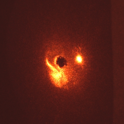
Here, for comparison, are three photos of returns that
show serious disturbances in the dye solution. These are
direct crops from the originals, so there are no larger
versions. As mentioned above, the bright spot to the
right and slightly above the central hole is a
reflection from one of the end windows of the dye cell,
and is not part of the return beam.
Here is a photo showing part of the dye cell, close to
the mirror at the far end (away from the alignment
laser). You can see two beams in the dye, evidence that
the mirror is misaligned. That can also indicate a
distorted optical path through the dye, though, so you
need to be careful not to jump to conclusions. If you
have any doubt, move some dye solution through the
cell and watch to see how things change. If you can
still see two beams after everything settles, you need
to tweak the mirror alignment.
(The large version of this image is only 700 px across.
It is a direct crop from the original file; I
don’t have anything larger.)
Annals of the New York Academy of Sciences
(Yes, that A. L. Schawlow, the one who got the Nobel Prize.)
On to the second page of this set,
in which I try out some possible improvements...
To the Joss Research Institute Website
To my current research homepage
My email address is a@b.com, where a is my first name
(jon, only 3 letters, no “h”), and b is joss.
My phone number is +1 240 604 4495.
Last modified: Wed May 10 15:06:28 EDT 2017
![]()
Blue

Pulsewidth Measurements
A Bit of a FAQ
     X10 amp
1 -> |LASER| -> 10
      ^^^^^
     28 pump
      X4 amp          X4 amp
1 -> |LASER| -> 4 -> |LASER| -> 16
      ^^^^^           ^^^^^
     14 pump         14 pump
A) The system is running significantly over threshold,
and
B) You don’t saturate the gain of the laser
medium.


Reference
Volume 168, Issue "Second Conference on the Laser"
(February, 1969), Pages 703-714
DESIGN AND ANALYSIS OF FLASHLAMP SYSTEMS FOR PUMPING ORGANIC DYE LASERS
J. F. Holzrichter, M.S. and A. L. Schawlow, Ph.D.
This work is supported by
the Joss Research Institute
19 Main Street
Laurel MD 20707-4303 USA
Contact Information: