(January 5, 2010, ff)
This page details some things I am trying in an effort to
enhance the performance of the laser that I described on
the first page of this set.
This laser uses high voltages, and capacitors that can store lethal amounts of energy. It puts out a laser beam that can damage your eyes and skin, and it uses organic dyes, some of which are known to be quite toxic. It also uses flammable organic solvents.
It is important to take adequate safety precautions and
use appropriate safety equipment with any laser; but it
is crucially important with lasers that involve
high voltages and present a health and/or fire hazard!
(11 January, 2010)
Harald Noack, of Graz University of Technology, suggested that I try simmering and pre-pulsing the flashlamp. He cited an article in which the authors obtained 20% improvement in lamp performance just by simmering, and obtained further improvements in laser performance (particularly with blue dyes) and lamp lifetime by prepulsing the lamp.
Simmering involves passing a DC current through the lamp. With lamps that are driven at relatively low voltages this considerably changes the switching and triggering requirements, which ordinarily depend on a lamp that is not initially conducting. With a dye laser like the one here, however, the situation is quite different. A lamp that is already conducting should be, if anything, even easier to work with than a lamp that is not yet started.
Although the authors simmered their lamp at 20 mA, I have seen other papers that listed simmering currents as high as about 100 mA; Harald reports that his lamp works well with 10 mA simmer current, and I gather from this that any particular lamp may have a “sweet spot” that is perhaps best found by trial and error.
It seems to me that as long as the simmer current is present when the laser is fired, it should not be necessary to have it be present at all times. Eventually I will work up a pulsed simmer arrangement in which the simmer current is turned on perhaps 1 millisecond before the main store is discharged through the lamp, but just to get started I think that simply turning the simmer supply on shortly before pulsing the lamp and turning it off shortly thereafter should suffice.
In the meanwhile, however, my early trials with simmering (detailed on the previous page) did not give me the expected results. With either of the lamp types I have used in this laser, simmering impairs the performance. For this reason, I am [temporarily] abandoning it in favor of other techniques.
I should note that the authors of the paper specifically
state that the improvement in performance that they saw
with simmering resulted from improved imaging of the
lamp on the dye cell. I am not imaging anything; my
lamp and dye cell are close-coupled, so it comes as
no surprise that I did not observe the same improvement
in performance that they did. By the same token, however,
I still do not understand why there was an impairment.
With the lamp from The Electronic Goldmine in place, I find that the circuit I’m using is underdamped, and oscillates. With the other lamp, which has very different characteristics, it does not. I mentioned this to Harald, and he suggested that I try two of the Goldmine lamps in series. That would allow me to decrease the inductance of the driver circuit by moving the conductors closer together, which should speed up the pulse a bit; I am hoping to try it, and I will present the results here.
(11 January, 2010, evening, and 12 January, early AM)
I have come up with a slight redesign of the driver circuit, which I built using thicker brass shim stock (6 mils, roughly 0.235 mm). Here are the paper mockups that I used as plans:
I built the actual version, assembled it, added some sheets of plastic to help avoid flashovers (see the photo on the left, below), and attempted to attach the lamps to it. In the process, the thin wire broke off one end of one of them, revealing yet another reason why I strongly dislike this typ of connection. Here are photos of my initial jury-rig:
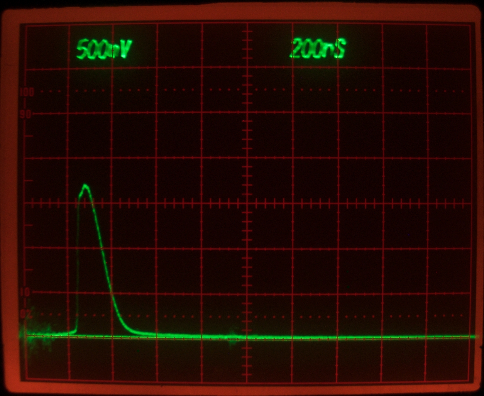
I expected this to fire with somewhat less oscillation than the original version, and I expected a faster pulse. This is what I got:
It looks fine, very much like the ones I took with the “robust” lamp (see previous page) and with only a tiny hint of a second peak, ...until you notice the timescale. In the photos on the other page, the sweep was at 200 nsec per division, while here it is at 500 nsec. The pulse is slow, and I have not been able to obtain any lasing yet.
Thinking about it...
(12 January, 2010, afternoon)
Jarrod Kinsey asked a question in email that caused me to remember a different configuration, one that I first thought about some years back but was unable to build at that time because it requires two capacitors with essentially the same value. I obviously have two such capacitors now, and I am going to rebuild this driver in that configuration. We’ll see how it works.
(Later that evening)
Here is the configuration, a simple voltage-doubler circuit:
(This circuit is similar to the ones often used in nitrogen lasers, where it is usually described as a “Blumlein Circuit”, which is ridiculous: Blumlein’s actual circuit design involves matched transmission lines, a matched load, and an extremely fast switch.)
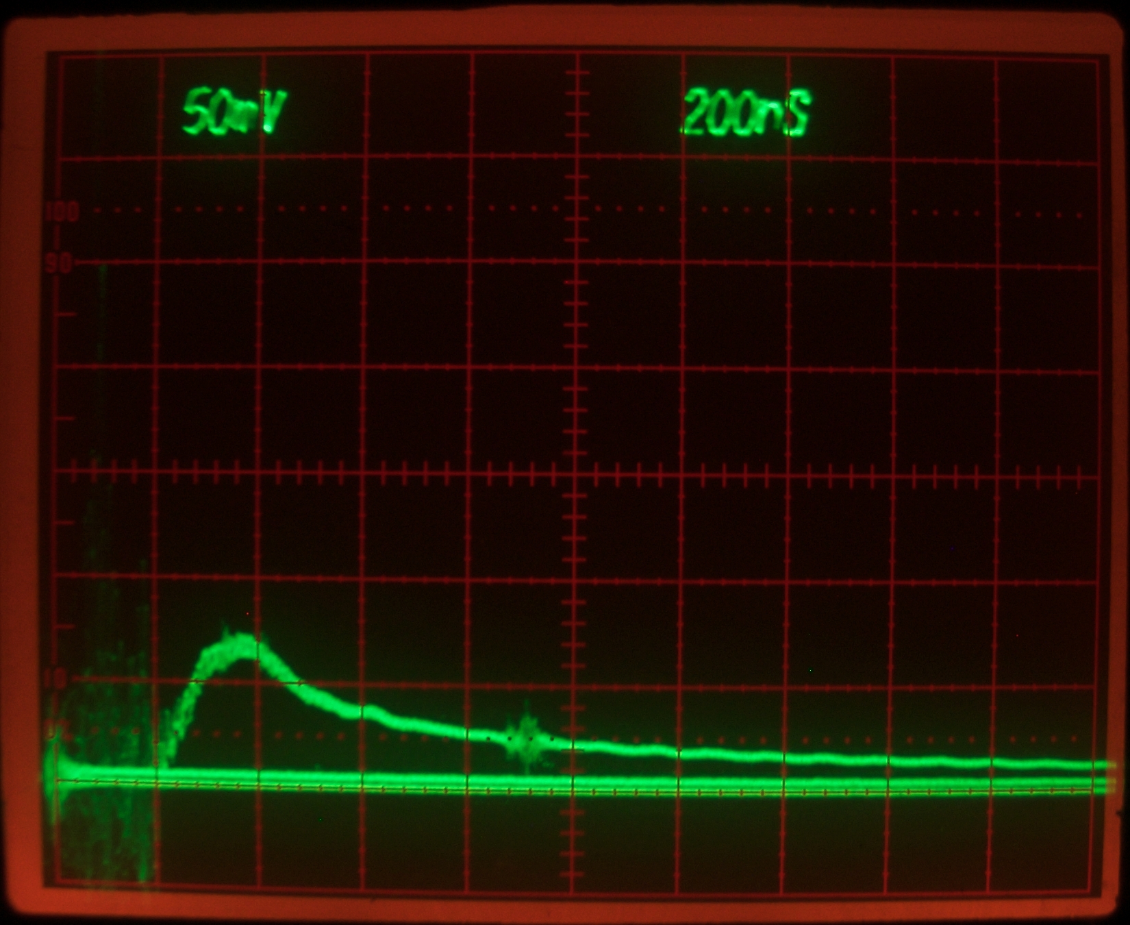
I expected faster risetime and possibly a more narrow pulse. This is what I found:
We are back to 200 nsec per division, which is good. The
pulse rises smoothly, in about 400 nsec, and appears to
be a single peak. Occasionally, though, I see the
leading edge as it appears in the second photo, with a
plateau about halfway up (give or take a bit).
Sometimes the plateau is more pronounced than it appears
in this photo. Moreover, sometimes the lamp does not
flash, and I have not yet seen any trace of lasing. My
suspicion is that this driver is not getting enough of
its stored energy into the lamp. It was certainly worth
a try, however, and I may test it with the other lamp,
to see whether there is much difference.
(13 January, 2009, evening)
In thinking about this circuit and the results I
obtained, I concluded that there was another handy way
to get a fairly fast risetime and high voltage: instead
of a voltage-doubler circuit, what about a single-stage
Marx generator? The difficulty with a Marx generator or
Marx bank is that it presents the full power supply
voltage at its terminals during charging. This means
that unless the load will ignore the power supply, you
need another switch of some sort. The easiest way to
accomplish this is to put a free-running spark gap in
series with the output.
I was all set to build one, when I discovered that I had
already done so. It isn’t very fancy, and it is a
bit smaller in diameter than I had in mind, but it was
there, so I used it. (Photos of this setup forthcoming).
I suspect that my flashlamp has ceased to be a lamp
and is now an inert piece of glass, because it failed
to fire, and I got flashovers when I added a close-wrapped
aluminum-foil reflector. Nonetheless, the sparks of the
flashovers gave me enough light that I was able to get
a trace from the oscilloscope. It looks like this:
The risetime is now about 125 nsec, and the pulse is
no more than about 400 nsec FWHM. This looks good, but
it is important to remember that a piece of aluminum
foil is not exactly the same thing as a flashlamp. I
will have to try the “robust” lamp, to see
whether I can get a proper flash out of that.
(Later that evening)
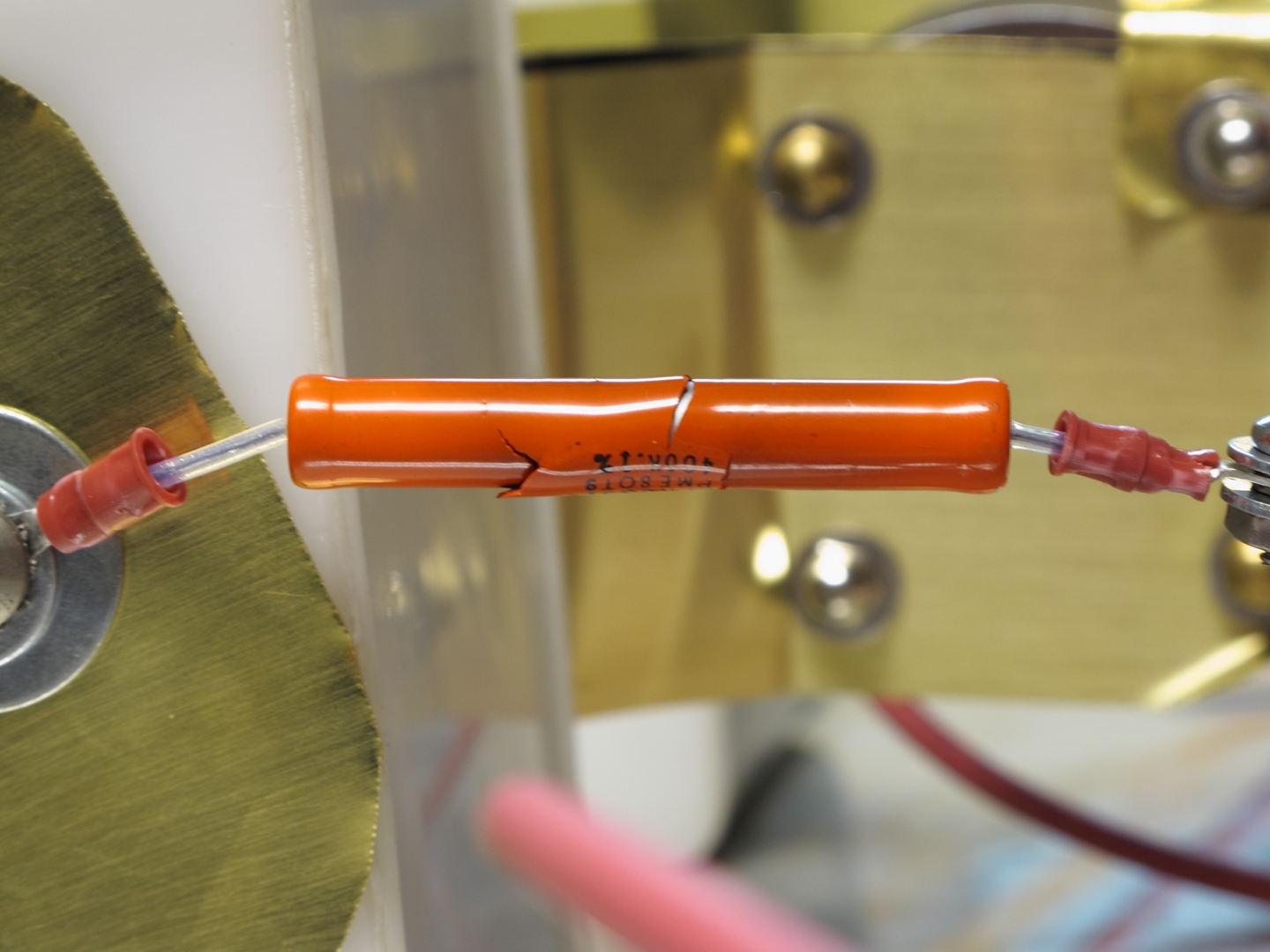
It seems that I need more resistance in series with the
power supply output; I think the spark gap continued to
conduct after one of the flashes, and damaged the 400 K
HV resistor that is on one of the caps:
(I have 800 K on the other cap, and that appears to be
enough.) The pulse, however, is just fine —
risetime still less than 200 nsec, pulsewidth just about
400 nsec:
This was just a temporary lashup, however. I need to
find a better way to hold the lamp in contact with the
brass shims before I will be able to run the laser
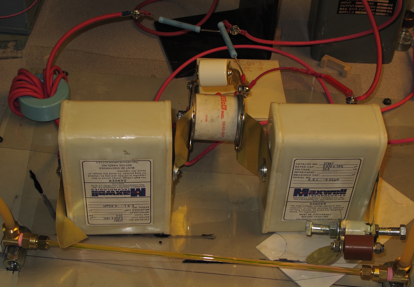
again. Meanwhile, here is an overview of the Marx setup,
without the lamp:
The brass shims on the main spark gap are considerably
longer than they need (or want) to be, and eventually
I will shorten them. That should give me just a bit
more speed.
(14 January, 2010, early evening)
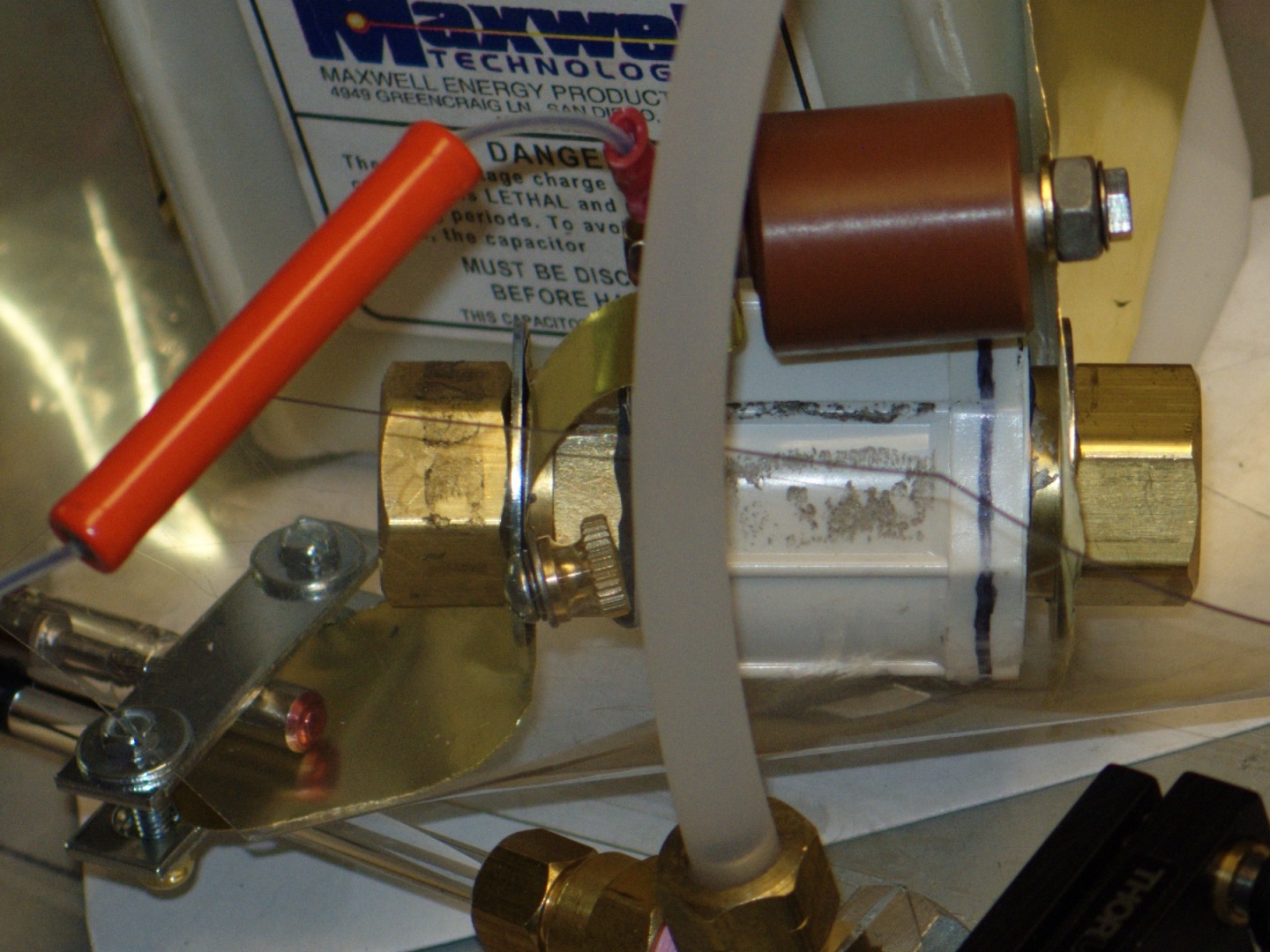
I ended up holding the ends of the lamp this way:
(The large bolt is part of the peaking gap, and is not
related to the clamp.) The contact area between the lamp
end and the brass shim is considerably smaller than I
would like, but it will serve for now. I am thinking
about better clamp designs.
It should come as no surprise that this device is a laser.
Unfortunately, the peaking gap no longer holds off
the power supply voltage, so I was unable to take a
scope trace of the laser output. I will be obliged
either to rebuild the gap, or to build a new one.
Still, this design has clearly proven itself. I should
probably note that the dye solution shown here has been
in the laser for several days, and should have been
replaced. It worked anyway.
(Later that evening)
When I opened the gap to inspect it, I found a small
burned area on the plastic:
That was all it took to unbalanced the field and cause
the gap to fire at [relatively] low voltage. To help
prevent tracking across the surface, and to decrease the
influence of small burns, I am switching to a plastic
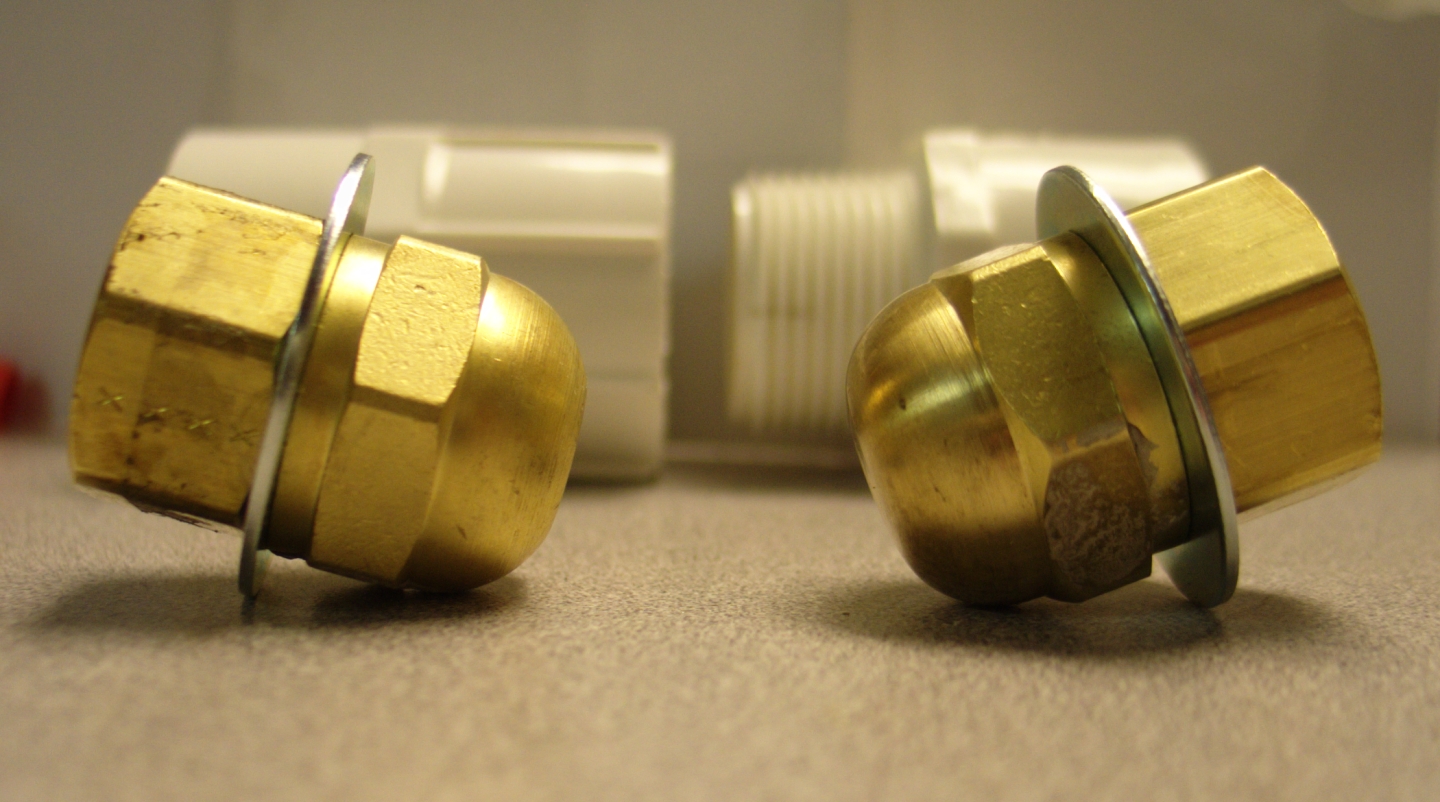
shell that has internal threads. Here it is with one of
the acorn nuts present:
When the RTV has set I will put the other acorn nut
in, and I think I will be drilling some small holes
in the envelope to allow some airflow. Otherwise,
it gets quite hot in there with repeated pulsing.
(15 January, 2010, morning)
I drilled holes around the housing of the gap,
sanded the outer faces of the acorn nuts for
better contact, and tested the gap. The spacing
was not wide enough, and the driver self-flashed
several times (I checked, and it did lase), so
I turned it off and I’m moving the acorn
nuts a bit farther apart.
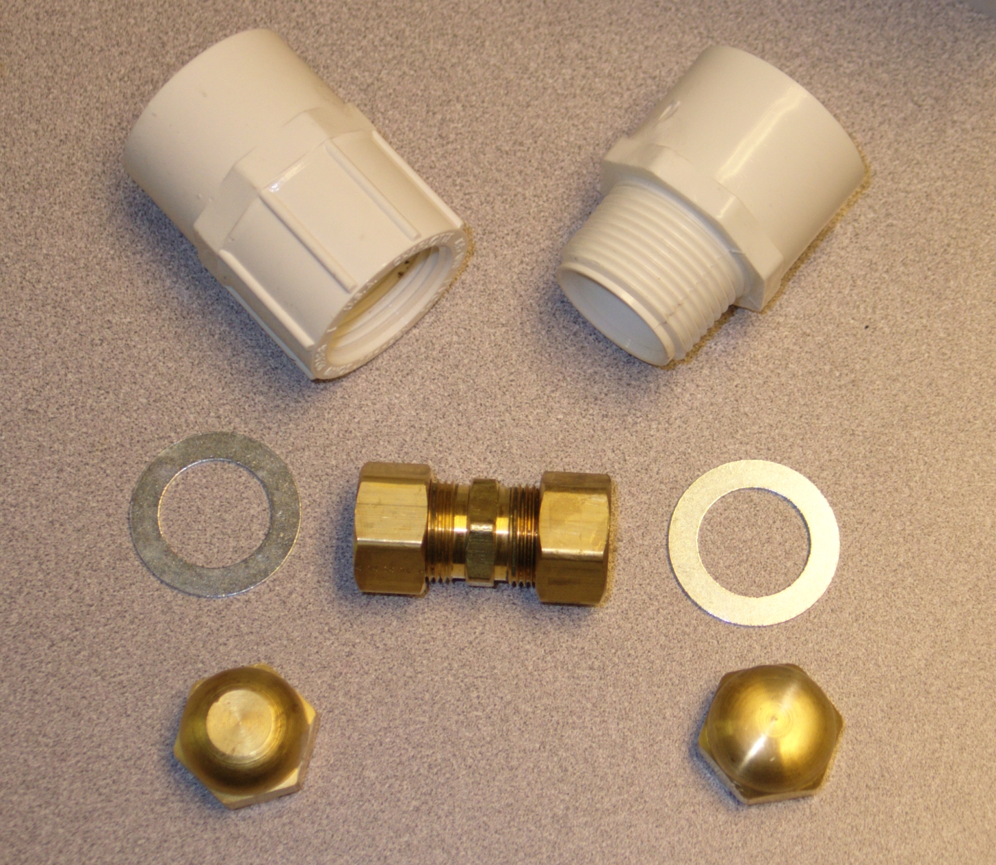
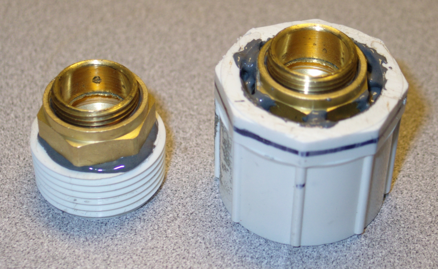
I am also building another gap, with adjustable
spacing. Here’s my idea, in parts:
I have used a hacksaw to remove the two threaded
sections from the 5/8" compression fitting, and I am
currently epoxying them into the electrodes; they are
just barely long enough, fortunately. I’m holding
them in place with the compression nuts from the
fitting, which will later hold the machine bushings
against the brass shims, compressing them onto the backs
of the electrodes. I must now be patient, and wait for
the epoxy to cure.
In the meanwhile, the original gap is now wide enough to
hold off the HV supply, so I took a look at the
laser’s output:
(This is the same tired mixture of Fluorescein and R6G.)
Nice steep leading edge, with risetime (if you
don’t count the little dip just before the peak)
of ~10 nsec; the FWHM pulsewidth looks like it’s
on the order of 120 nsec.
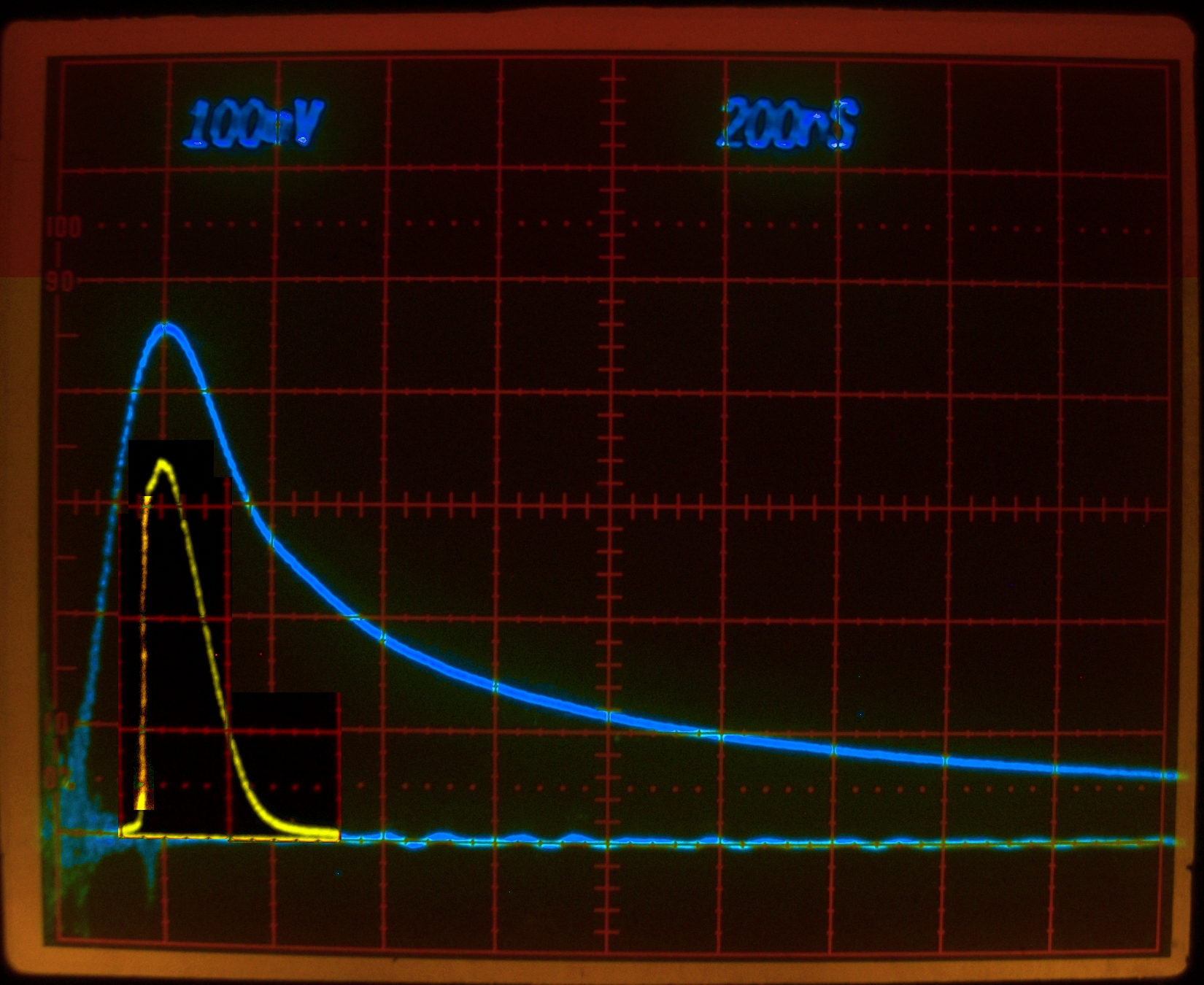
I am slightly reluctant to superimpose this trace on the
lamp trace. For one thing, the lamp trace was taken
without the aluminum foil close-wrap, though I would not
actually expect that to make a particularly large
difference. In addition, I’m not fully certain
about when the trigger events occurred. I am fairly
sure, though, that the dye laser pulse (in yellow)
cannot reach its peak after the lamp light does, so I
have positioned it with that in mind. (The fluorescence
lifetime of the dye is quite short, so the dye solution
can’t store energy for more than a very few nsec.
As the lamp pulse peaks and begins to decrease, the
fluorescence [and lasing] will also start to decrease,
in a time too short to be visible on the screen of the
oscilloscope at this sweep rate.)
(I have brightened the leading edge of the laser pulse
here, to make it easier to see.)
Here is an actual lamp pulse trace, with the laser running:
Here’s a version with the vertical scale expanded,
to make it easier to see the shape:
The risetime looks like 150-160 nsec, and the pulsewidth
is perhaps a little less than 400 nsec. Slightly slower
risetime than I got without the reflector, but the
pulsewidth doesn’t seem to have changed much.
Here is the R6G output on the wall, roughly 7 feet
away from the laser, with the room lights turned out:
Here is the rebuilt spark gap, in place on the lamp driver:
Here are the two electrodes of the new gap, with the
threaded sections from the compression fitting epoxied
into them; the compression nuts are next to them, and
the PVC fittings that I will be sawing apart to make
the gap housing are in the background, with the bushings
leaning against them:
Here they are again, with the bushings and compression
nuts on them:
I have not yet built the housing, but it shouldn’t
be too difficult..
(18 January, 2009, early AM)
Here are the halves of the new gap:
Once again I must be patient, and give the epoxy
time to cure thoroughly.
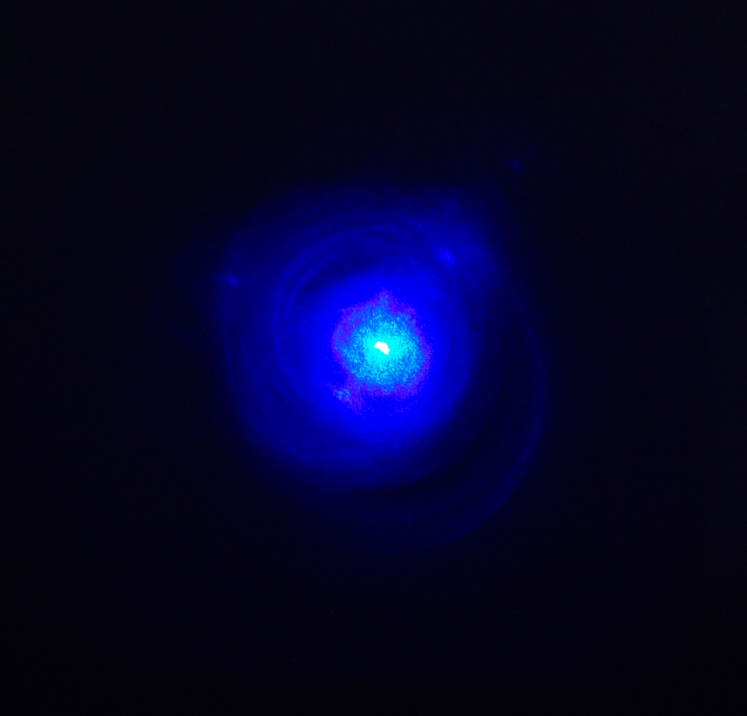
Meanwhile, although I was not able to get a trace
of the output from “Optic Whitener”, as
I do not yet have the dye solution properly adjusted
(and the mirrors may not be aligned as well as they
should be), I did get a photo of the output on the wall:
This is a bit ragged, and I will be fussing with the
solution at some point, to see whether I can get
better results. I may also try a different output
coupler.
(18 January, 2010, evening)
I assembled and installed the new gap:
You can see a 30-Megohm HV resistor at the upper left;
it is 1/3 of the bleeder resistor that is across the
flashlamp. I managed to get a few traces of the lamp
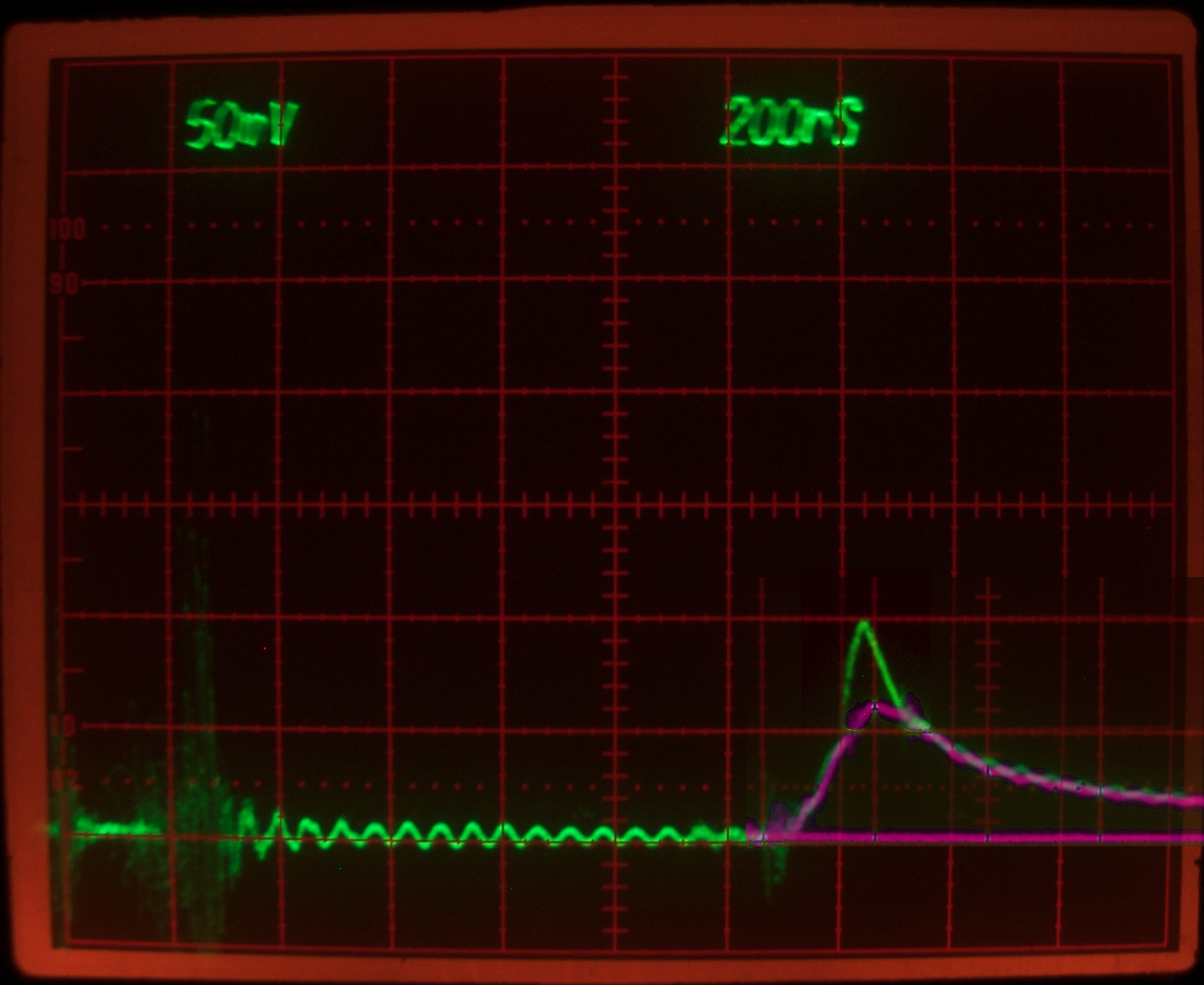
output without lasing, and one with Optic Whitener
lasing. Fortunately, one of the nonlasing lamp traces
was just almost the right height to match the laser
output trace (they were taken with the detector in the
same position, which helps), and I was able to
superimpose them. Triggering was unstable, so the
divisions on the face of the scope are not in the same
places in both images, but the timing of the laser pulse
with respect to the lamp pulse should be reasonably
accurate — the traces overlap nicely where the
laser is not running.
The lamp pulse, very handily, has its peak right on
one of the vertical lines on the scope face, so it is
easy to see that the peak of the laser output actually
appears to occur slightly before the peak of the
lamp output. I am not sure why this should be, and I
will be keeping an eye out during further testing, to
see whether it seems to be common. (It could, of course,
be an artifact.)
(20 January, 2010, evening)
This afternoon I tried adding a small amount of sodium
hydroxide to the dye solution, to see whether Optic
Whitener is compatible with it. This is partly because
I had a hunch it might improve the output slightly,
and partly because I wanted to try mixing Fluorescein
into the solution, and Fluorescein has higher fluorescence
efficiency in basic solutions. As far as I can tell on
a single trial, NaOH does help Optic Whitener a tiny bit,
and it also appears that Optic Whitener helps Fluorescein,
perhaps partly by energy transfer, but almost certainly
by emitting light that can pump the Fluorescein.
(22 January, 2010, evening)
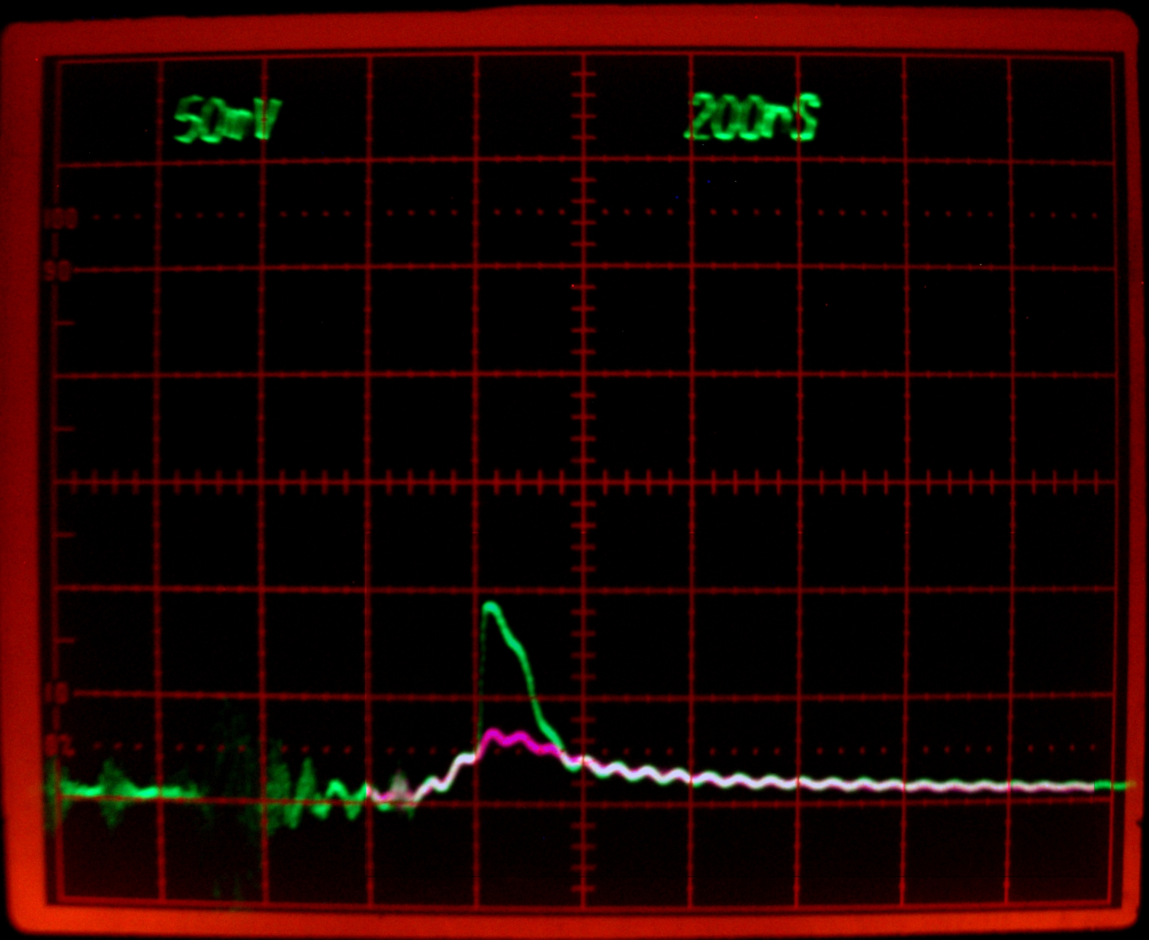
This is just Fluorescein (plus some NaOH); no other dyes
are present, at least not intentionally.
(Again, I was fortunate enough to capture a lamp trace
that is about the same amplitude as the lamp portion of
the laser trace, so I could superimpose them.
(23 January, 2010, evening)
Thinking about the performance of the laser since I put
the new gap in, I wondered whether it might be spaced a
little too wide. My logic here is based on the fact that
the laser ran with the older gap, even when it was too
closely spaced and was going off on its own. (The other
end of that spectrum would be a gap so wide that it
didn’t conduct even at the full 40 kV, which would
result in 0 J being delivered to the lamp.) I
haven’t really researched this, but my sense is
that in the absence of conflicting factors the gap
wants to be spaced as closely as possible, consistent
with good control of the Marx generator. Having
concluded this I removed it from the driver, screwed the
insert further in (about 2 turns, I think), and put it
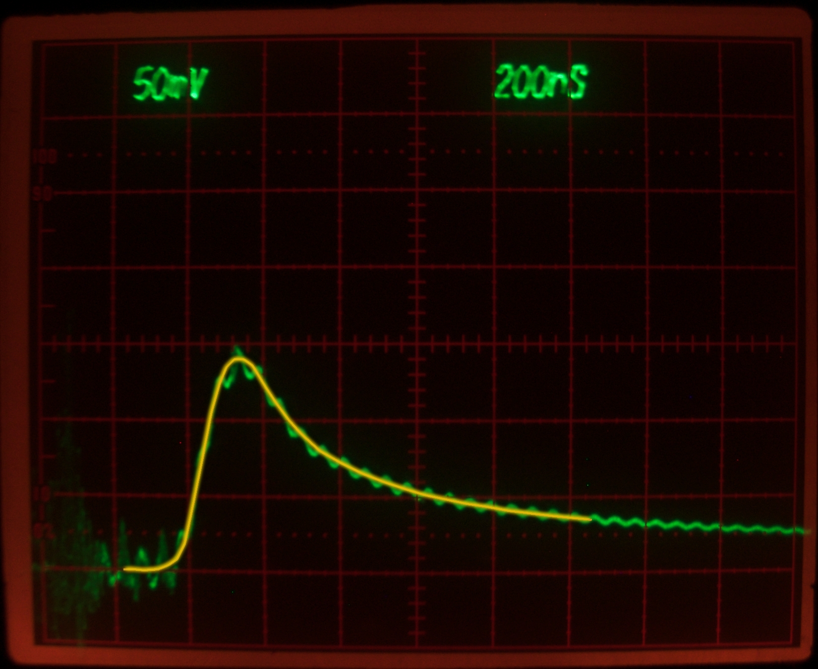
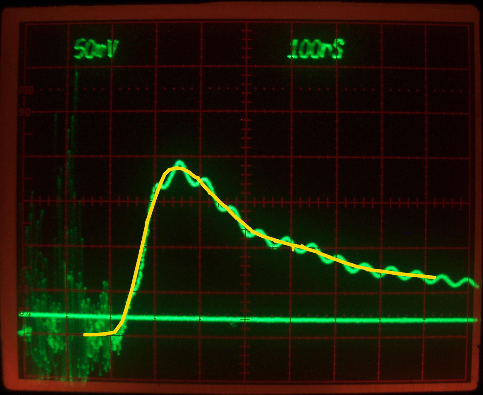
back in. Here is a lamp trace, over which I have drawn a
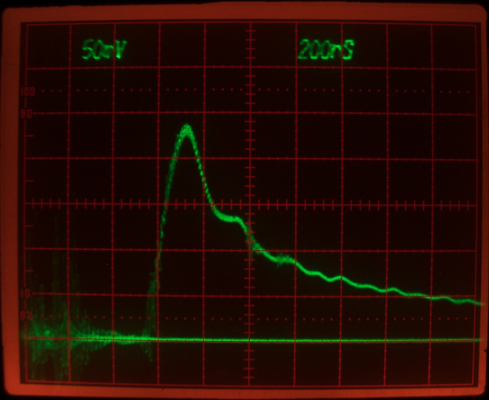
smoothed version:
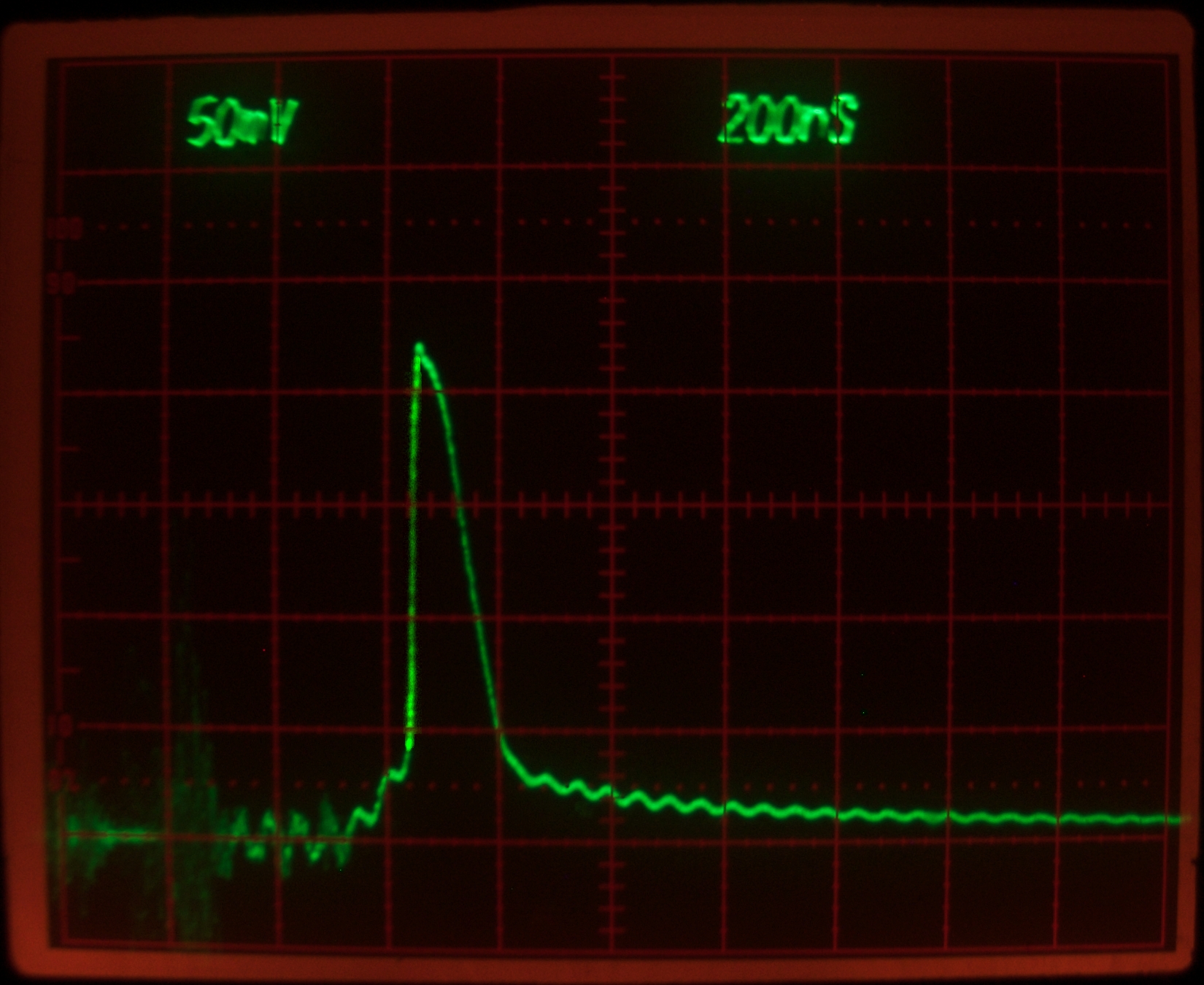
Here is a laser trace. (As before, I have brightened
the leading edge, which was so fast that it was rather
dim.)
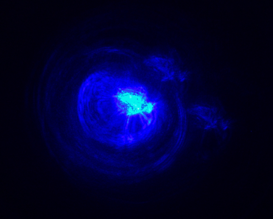
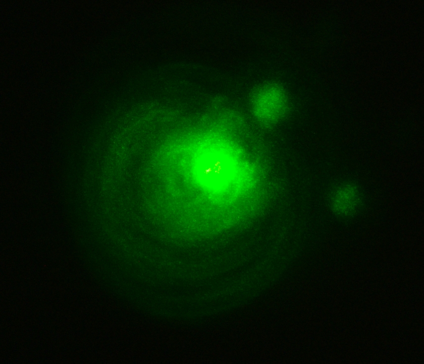
Here is a fairly typical “far-field”
pattern, as usual on the wall about 7 feet from
the laser:
I think this represents something of an improvement.
The lamp risetime is back to ~125 nsec, and the lasing
seems brighter. (Note, added 24 January, 2010, evening:
I strongly suspect that one reason why the lasing is not
as bright with Fluorescein as it is with
7-Diethylamino-4-Methyl-Coumarin is that the output
coupler I’m using is optimized for blue, not
green. I may have a better OC for green, and if I do I
may test this notion.)
(24 January, 2010, late evening, about an hour after
I added that note)
This should serve as a reminder that most of the
parameters of a FLP dye laser can be optimized. (In
fact, many parameters of most projects can be
optimized!) Assuming it was labelled correctly, the
output coupler currently in place has 6 meters radius of
curvature (so I have faced it toward the dye cell rather
than away), and transmits 1-3% between 520 and 531 nm. I
did a particularly careful alignment when I put it into
the mirror mount...
(Sorry about the shadow on the left side; it’s
a power cord that was in the way.)
(25 January, 2010, late evening)
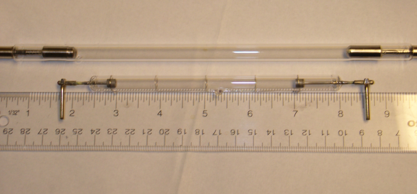
The new lamps I ordered from Electronic Goldmine have
arrived, so I installed one. I must point out that they
are quite fragile; you will need to be extremely careful
when you clamp the ends. (Yes, I broke one.) Here is one
of the new lamps, as shipped, next to the “good”
lamp, with a ruler for scale:
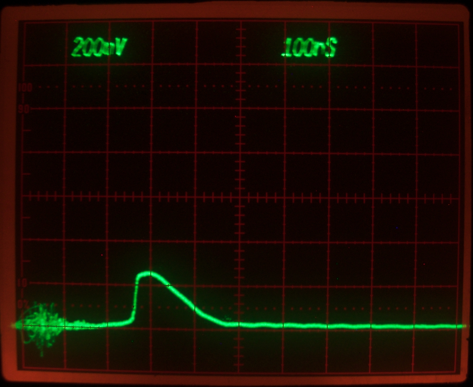
Despite my misgivings about the short arc length (10 cm
/ 4"), this lamp performs well. Here is a trace of its
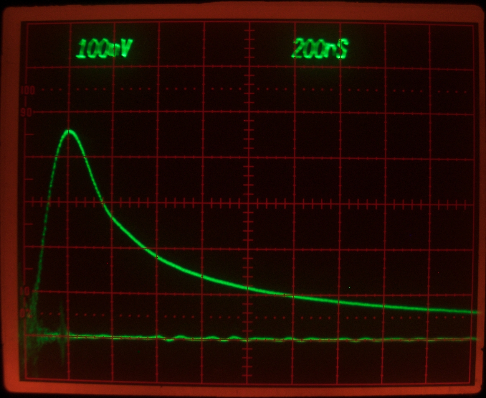
output, this time at 100 nsec per division. I have drawn
a smooth curve (which is regrettably crude, and for which
I apologize) over the noisy original.
Notice that the risetime is now about 100 nsec, while the
FWHM pulsewidth is still roughly 400 nsec. For whatever
reason, this lamp appears to be a good match to the
driver circuit.
Here is the laser output, also at 100 nsec per division:
Again, the risetime is quite short; the FWHM is very
roughly 120 nsec, which is quite acceptable.
(Notice that this was taken with the vertical sensitivity
turned down. When I tried it with the same vertical scale
as the lamp output photo, it went right off the top of
the screen. Unfortunately, there is a problem with this
vertical amp, and I need to get it recalibrated; the pulse
should be somewhat taller than it appears here.)
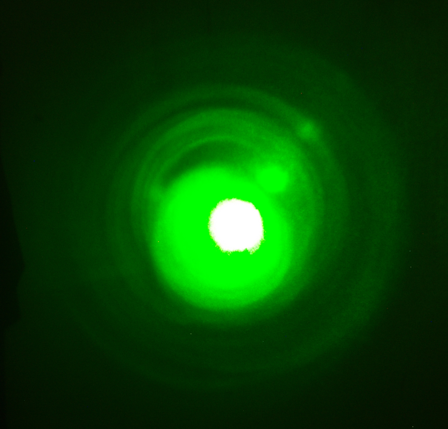
(26 January, 2010, late evening; photos taken early AM)
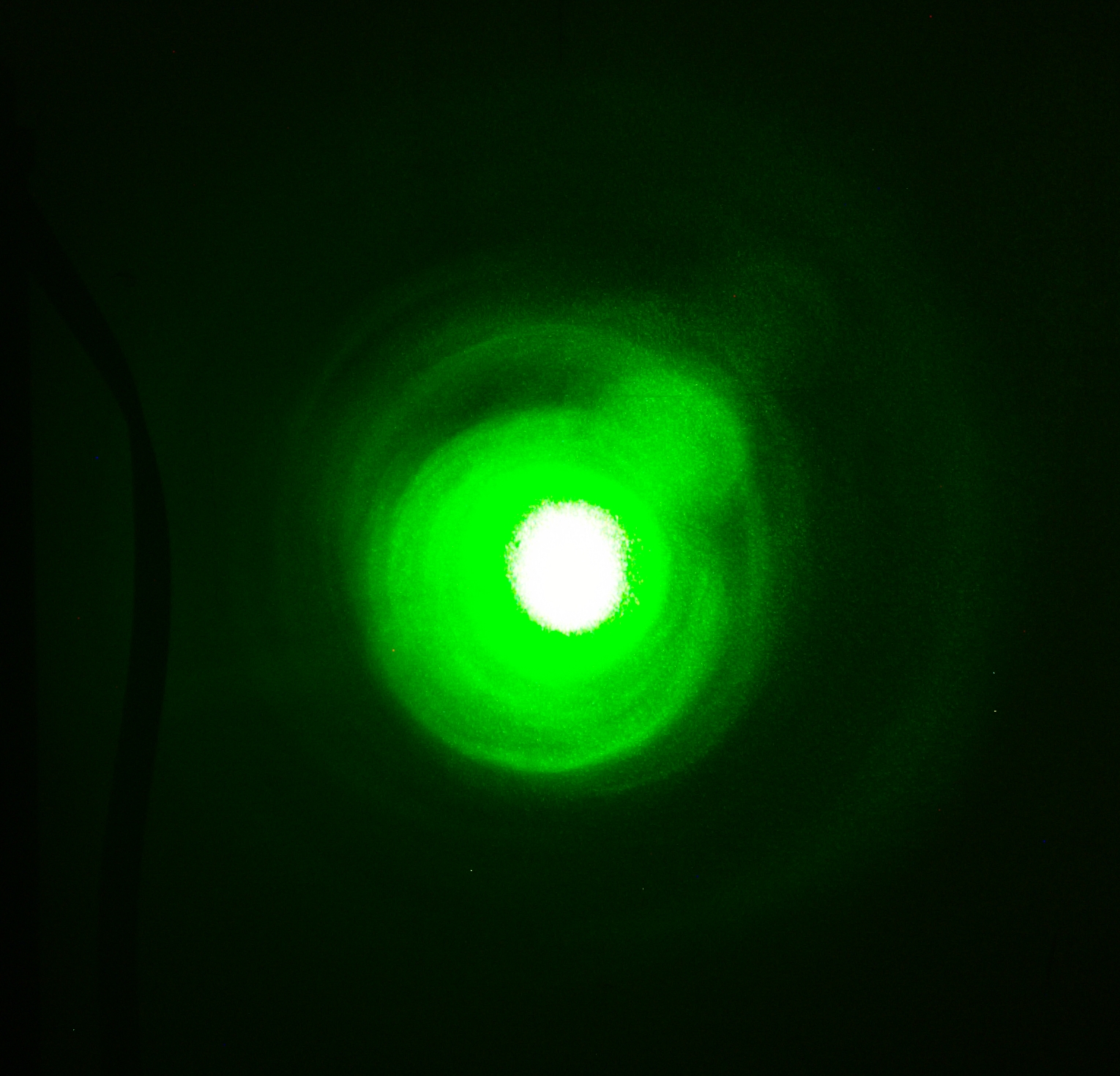
I decided to check some things. First, here is a
reasonably representative photo of the output on the
wall, with the new lamp:
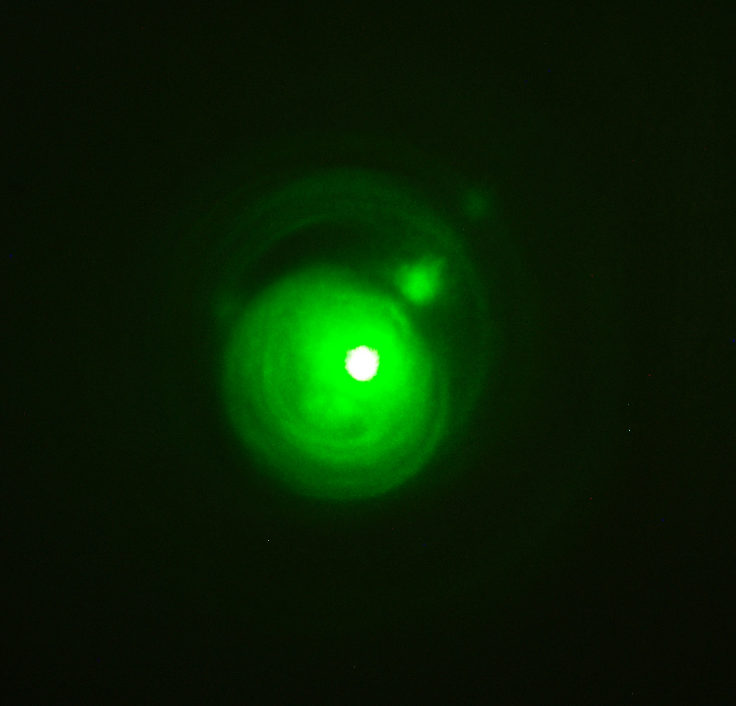
I added a small amount of “Optic Whitener”,
to see whether it would help. It did not:
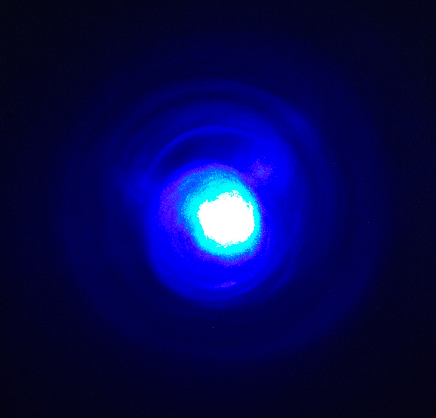
Then I emptied and rinsed the dye cell, and set it up
again with 7-Diethylamino-4-Methyl-Coumarin
(“Coumarin 1”) in 91% isopropanol, to see
whether that would work with an output coupler that is
optimized for green rather than blue. Answer:
That is, not as well as it would with a mirror optimized
for blue, but it certainly isn’t bad.
Please note, btw, that all of these are essentially
identical crops from the originals, so they are directly
comparable in terms of the size of the pattern. The next
one is also comparable.
Note, added later: I have some doubt as to the green
pattern just above the first Coumarin 1 pattern. It’s
visibly different from the others. Unfortunately, I have no easy
way to check at the moment.
(29 January, 2010, late evening)
As part of the next phase of this project, I have
installed a peaker capacitor, on a temporary basis,
as a proof of principle. The details are on the next
page, but here, for comparison, is a photo of the
output:
This is considerably less pronounced than the similar
one above, but there are good reasons for that.
(20 January, 2010, evening, updated 04 February, 2010)
I initially said I would be remiss if I failed to
mention the fact that this laser is often more finicky
than I would like, but as of early February it is
behaving itself considerably better. I can pulse it
faster than once per second if I have the dye flowing
at just the right speed, and when the mirrors are
properly aligned it puts out a fairly reasonable
beam. I think the lesson here is that if even one
key parameter is marginal the machine will be
difficult to deal with; and if more than one parameter
is out, the machine is guaranteed to be painful if it
works at all.
Before I put a pump in, though, I may want to try replacing
the end windows on the dye cell, as the nice AR-coated
ones have arrived and are waiting. I keep thinking that
they should be better than uncoated bits of microscope
slide. (I did end up putting coated windows in place,
and they certainly aren’t any worse than uncoated
ones. My sense is that they are better, but it is very
difficult to make the relevant measurements to be entirely
certain.)
In its current (Marx generator) configuration it is also
quite loud, and I have been wearing earplugs whenever I
work on it. If I weren’t making frequent changes,
I would probably put it inside a protective box. If you
build one of these, please be careful of your hearing;
like your vision, it cannot be replaced!
I have already mentioned the fact that the shims on
the main switch are longer than they should be, which
is at least slightly slowing down the pulse. I am also
still using the special flashlamp, but I should be able
to swap that out within a few days, as the other ones
are on their way. (See above. As of 2010.0125 evening,
this has happened. Also see the next page in this set.)
(06 and 11 January, 2010)
In order to make this work I need two power sources, two
switches, and a way to prevent the two pulses from
interfering with each other. I also need to be able to
set the timing of the two pulses with fair precision:
they need to be only a few microseconds apart, and I
do not yet know the optimal interval, or even whether
there is an optimum.
(Note, added 25 January, 2010: Frankly, the performance
is now so pleasant that I am reluctant to mess with it.)
More as it happens...
A simmered pre-pulsed flashlamp dye laser
Back to the first page of this set,
which covers the initial design and development of the laser.
On to the next page of this set,
which covers the next version.
My email address is a@b.com, where a is my first name
(jon, only 3 letters, no “h”), and b is joss.
My phone number is +1 240 604 4495.
Last modified: Wed Sep 26 13:47:15 EDT 2018
Performance and Utility Issues
Prepulsing
Reference
A. Marotta and C. A. Argüello
Journal of Physics E: Scientific Instruments
Vol. 9 (1976) pp 478-481
This work is supported by
the Joss Research Institute
19 Main Street
Laurel MD 20707-4303 USA
Contact Information: