(January 20, 2010, ff)
This page details another step toward a DIY
flashlamp-pumped dye laser that stores a very modest
amount of energy at relatively high voltage, and
involves a minimum of expensive commercial components.
This design stage will, I hope, show that a
Charge-Transfer circuit is viable.
This laser uses high voltages, and capacitors that can store lethal amounts of energy. It puts out a laser beam that can damage your eyes and skin, and it uses organic dyes, some of which are known to be quite toxic. It also uses flammable organic solvents.
In some of its configurations it uses spark gaps that generate powerful acoustical pulses when the laser is cycled; these pulses can (and will!) damage your hearing if you do not use adequate protective gear. (The earmuffs used by shooters should be sufficient; foam earplugs may or may not be.)
It is important to take adequate safety precautions and
use appropriate safety equipment with any laser; but it
is crucially important with lasers that involve
high voltages and present a health and/or fire hazard!
(20 January, 2010)
The previous version of this laser, or at least of its flashlamp driver, used a single-stage Marx generator and a single isolation gap. I expect this version to use the same Marx bank and the same isolation gap; but instead of driving the lamp directly, it will charge a liquid-dielectric peaker capacitor, which will then discharge through a second passive gap into the lamp. This does not increase the efficiency of the lamp driver; to the contrary, at this point it is a waste of energy. The Marx, however, is a stopgap measure, and I am looking toward a further version that eliminates it. In that version, the peaker cap is necessary.
It would certainly be possible to use a commercial capacitor, but I am trying to move away from those. A liquid-dielectric cap is relatively easy to build, all things considered, and should be very fast. It has two disadvantages: first, that it requires extremely pure water, if it is going to use water at all; and second, that it must be charged and then discharged within a very short time. (There is some “wiggle room” here if we use a mixture of water and ethylene glycol or, I hope, water and glycerol, as the dielectric: these mixtures should have longer relaxation times. The circuit, however, charges and discharges its peaker cap in well under a microsecond, so that should not be an issue. Moreover, I could avoid the issue of purification if I use glycerol instead of water.)
There may be reason to build a peaker of a different sort as an initial step, and I am quite willing to do so. That would not require specially treated water or carefully polished parts, which makes it more attractive. The obvious problem is that it would have to be huge in order to achieve the requisite capacitance (I am thinking about ~6 nf), whereas a watercap can be surprisingly small. If I use glycerol as the dielectric (dielectric constant ~40 at 25° C), and if I keep the plates ~2 mm apart, I need only about 53.5 square inches. Plates that are 7.5" square or 7x8" or 6x9" will do, and I may have a potential candidate on hand. Note: if this were for a nitrogen laser, I would be more concerned about the inductance, and I would probably try for closer spacing; but here that is not an issue, and wider spacing means less worry about flatness and polish, though it does increase the required area.
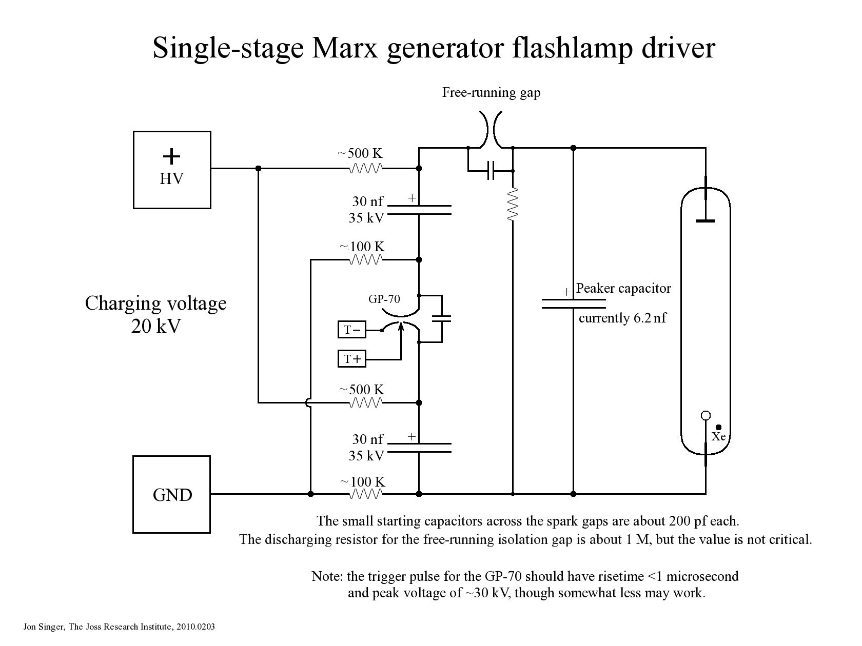
Note, added 03 February, 2010: Here is a schematic of the driver as it exists now; see below for various changes that led to this version and will lead beyond it.
(You can click the small version if you want to see a larger one.)
I should note that the isolation gap probably holds off about 30 kV; if it were not present, the output of the HV power supply would arc to ground through the flashlamp.
(23 January, 2010, early AM)
In order to be certain that the peaker will charge up to
a reasonable voltage before it begins to run the lamp, I
will have to insert another passive gap into the circuit.
Because I built a second gap for the Marx version of the
driver I now have a spare, which I intend to use. (Note,
added 04 February, 2009: I did, indeed, install a second
isolation gap, but it did not seem to improve the
performance of the laser, and I ended up removing it.
It is, therefore, not shown in the schematic above.)
(24 January, 2010, late evening)
I am decreasing the spacing on the older gap, which I
had increased when I rebuilt it, so that it would hold
off the power supply from the flashlamp. My goal is to
get it to flashover at something less than 20 kV; that
should allow the peaker capacitor to accumulate plenty
of charge before it is connected to the lamp.
(29 January, 2010, early AM)
I have started construction of a liquid-dielectric
capacitor. My initial thought is to use a
stainless-steel tray as one electrode, and a piece of
single-sided circuitboard that is glued to a glass plate
as the other. My first attempt uses very thin
circuitboard, and when I glued it to the glass it
didn’t come out as flat as I wanted; but frankly,
the bottom of the tray is not really flat either, and
with ~2mm spacing it probably won’t make a huge
difference. This will be a test capacitor, I think,
rather than an attempt at a final device, so I am going
to grit my teeth and go with what I have, rather than
scrap it at this early stage and force myself to start
over. (If I were more certain of how it will behave, I
might be more willing to pitch it; but I’m not.)
I will post photos here when I have a chance to take
some.
In the meanwhile, I am looking at ways of polishing
out the scratches on the bottom of the tray. Fortunately
I have two essentially identical trays, one of
which is scratched up much worse than the other, and
will serve as a practice piece. (1500-grit sandpaper
appears to be a viable step, but may not be a good
beginning for the process.)
(29 January, 2010, late evening)
This afternoon I remembered that I have two supposed
pulse capacitors here, rated 2 nf at 50 kV. This seemed
like a fine opportunity to try them out, so I installed
them as a peaker cap. This is a really crude setup,
intended only as a proof of principle:
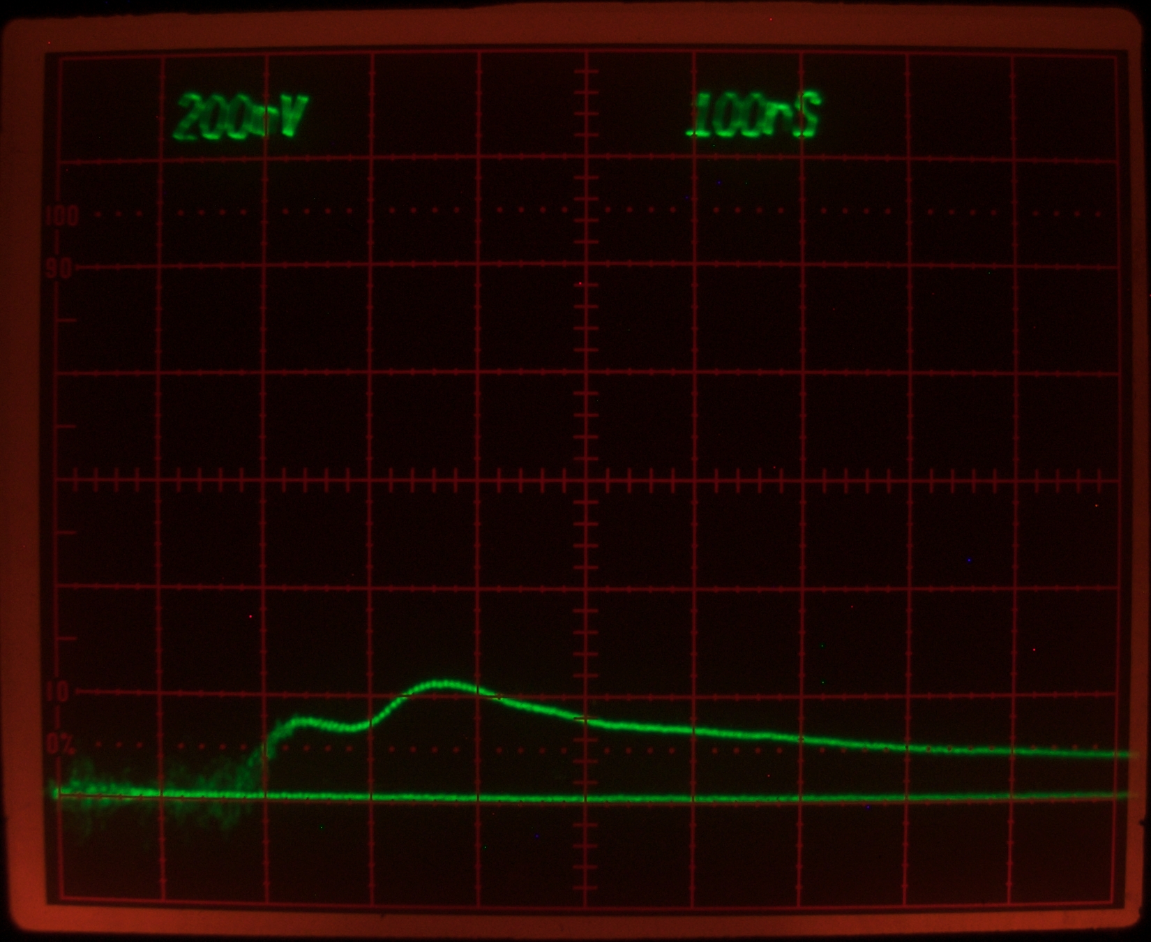
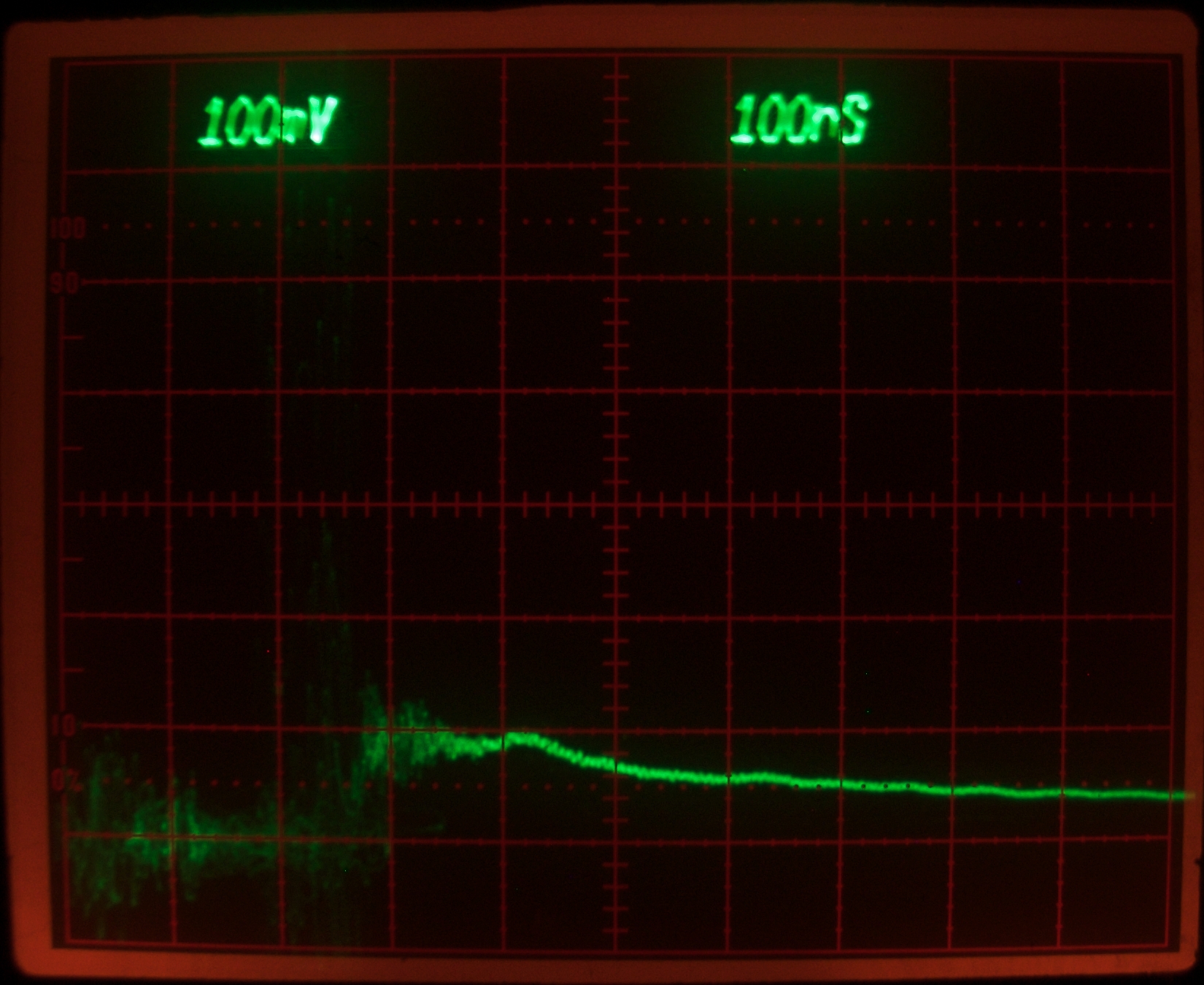
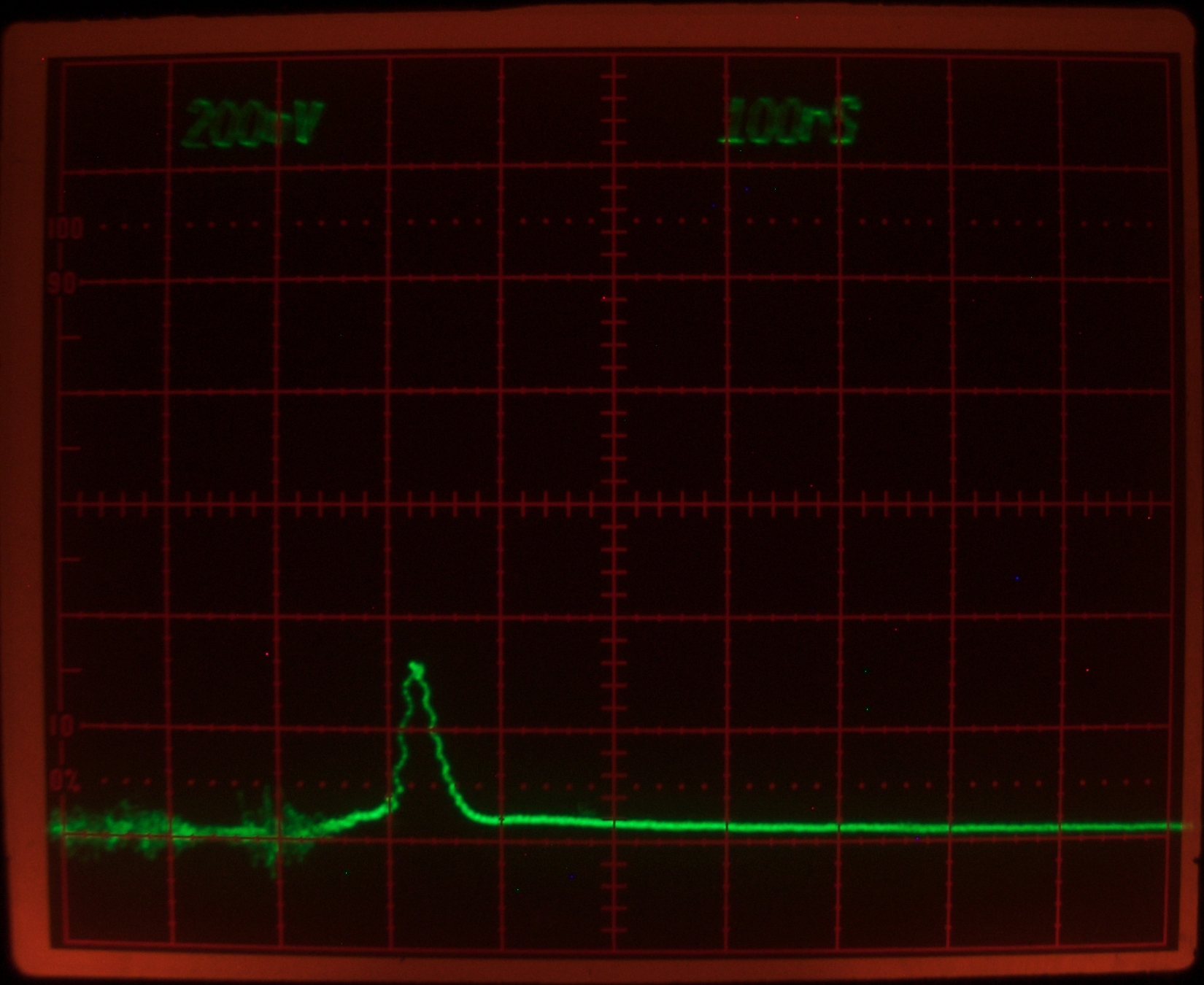
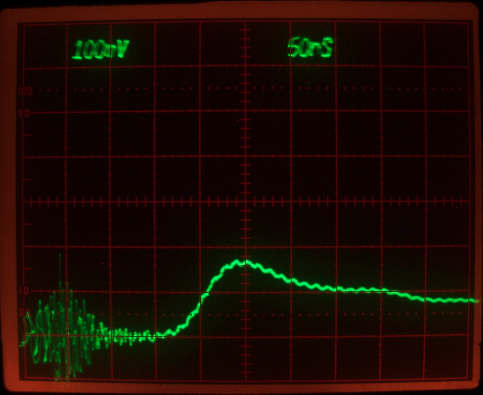
Here is a lamp trace, taken without any aluminum foil
wrapping:
The double peak is probably expectable; at 4 nf, the
peaker is significantly smaller than I would like, and
it probably isn’t very fast — I don’t
trust the capacitors to have low inductance. (The
risetime looks like about 80 nsec to me.) Still, it is
faster than the risetime of the Marx generator on its
own, and this configuration of the driver does do what
I wanted and hoped it would:
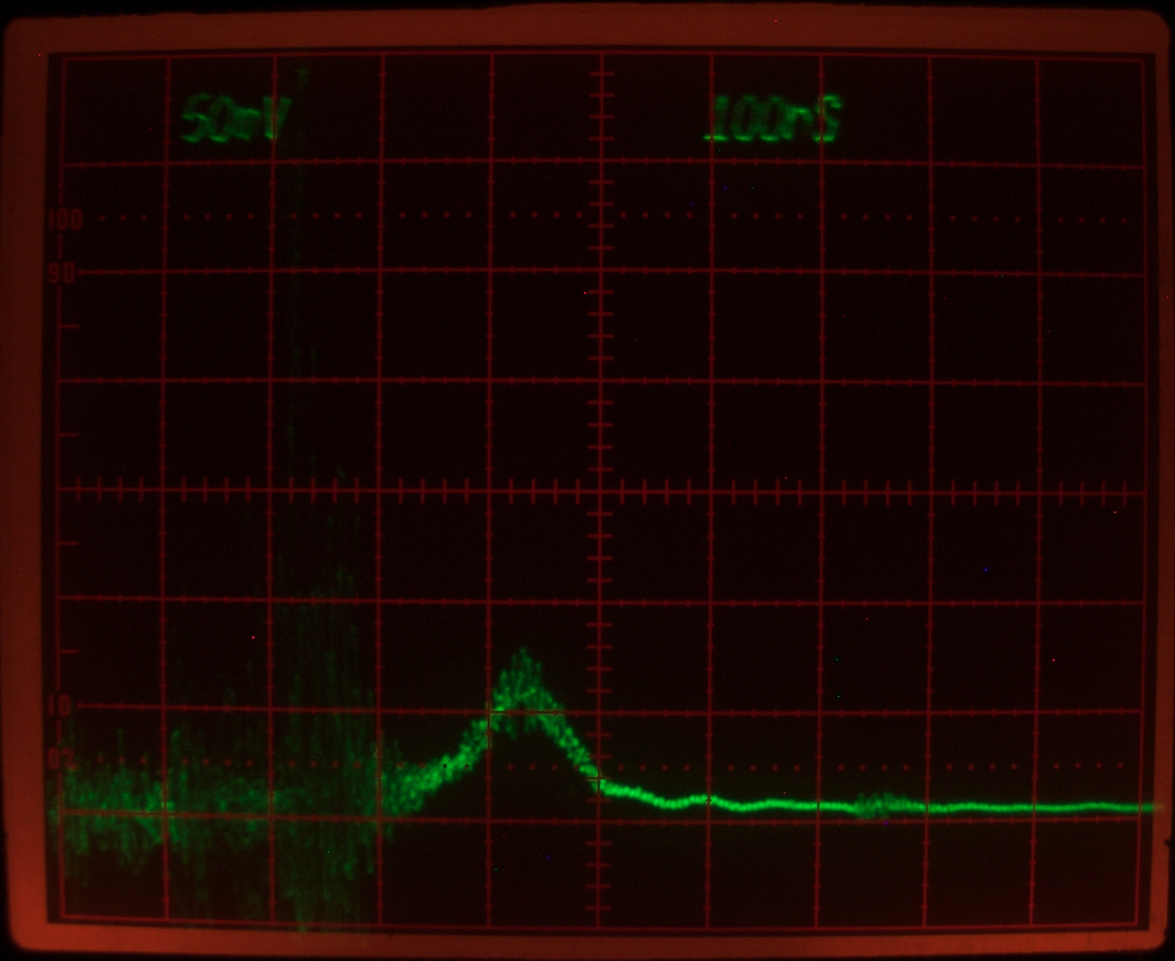
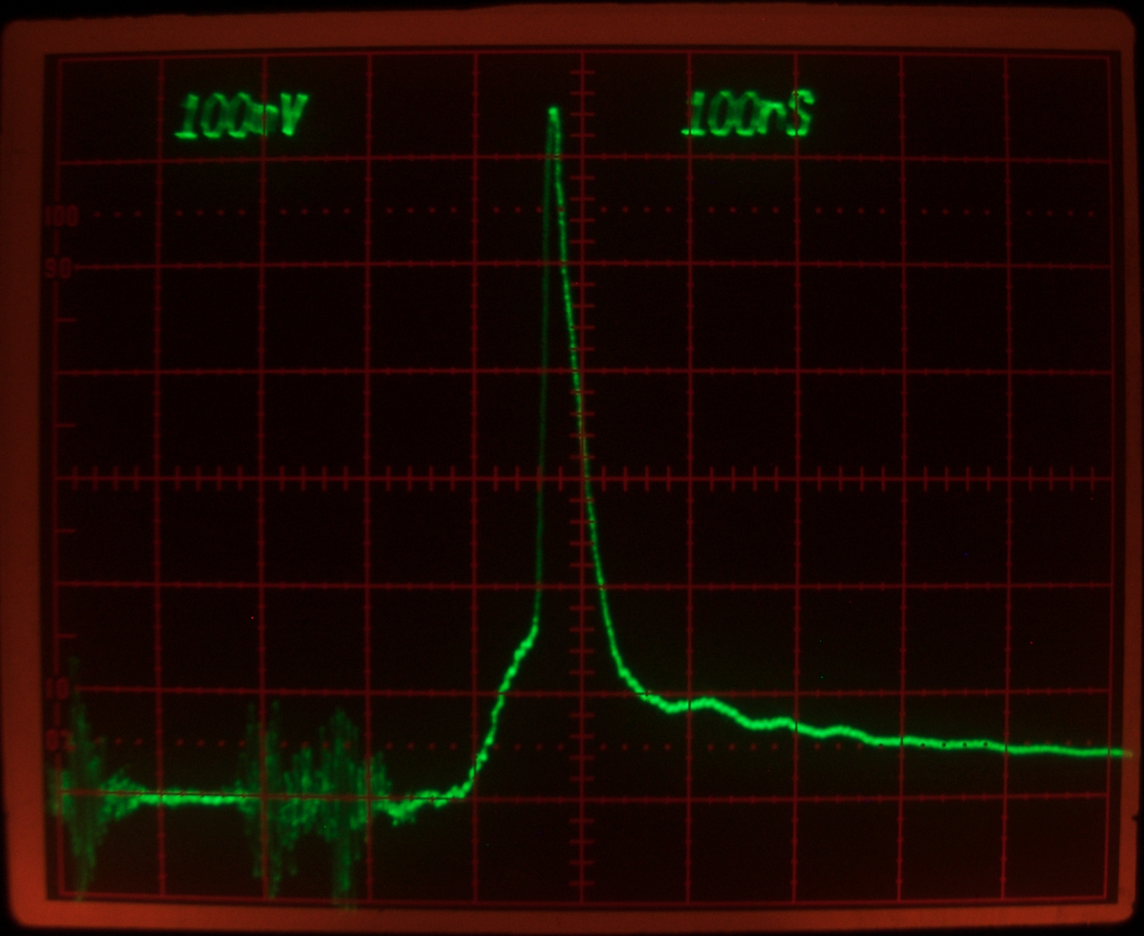
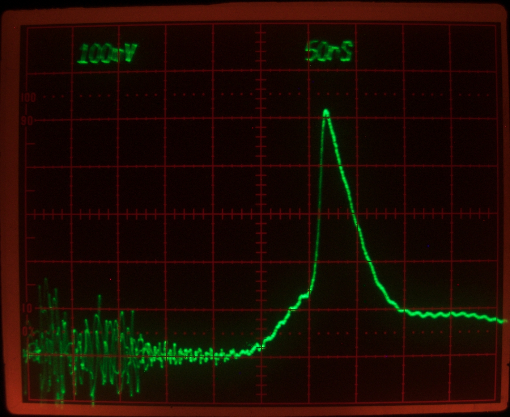
Here is a scope trace of a laser pulse:
Notice that the leading edge is much slower than the
ones in comparable traces on the previous page, and that
the pulse is more symmetrical. I am not sure what
governs this. (It may change when I get a larger and
possibly faster peaker cap built and installed.)
(30 January, 2010, afternoon)
In some cases, it is possible to use one dye to assist
another, either by direct intermolecular energy transfer
(typically, AFAIK, at relatively high concentrations, so
that the molecules are close to one another), or by
emission from one dye and absorption by the other. Here
is an example: the absorption spectrum of Fluorol 555
overlaps the emission of Coumarin 1 quite nicely, and
the emission of Fluorol 555 is reasonably well matched
to the output coupler that is currently in place. The
laser was already filled with Coumarin 1, so I added
Fluorol to the dye solution. The first thing that
happened was that the blue lasing was quenched. As I
continued to add more Fluorol, green lasing appeared and
then became stronger. This, by itself, does not prove
anything (except that Fluorol 555 appears to quench
Coumarin 1); but in a future test I hope to start with
Fluorol and add Coumarin, to show an enhancement effect.
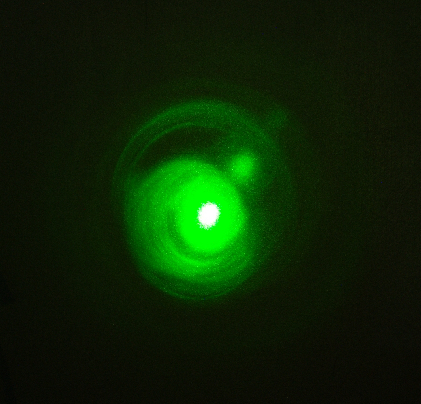
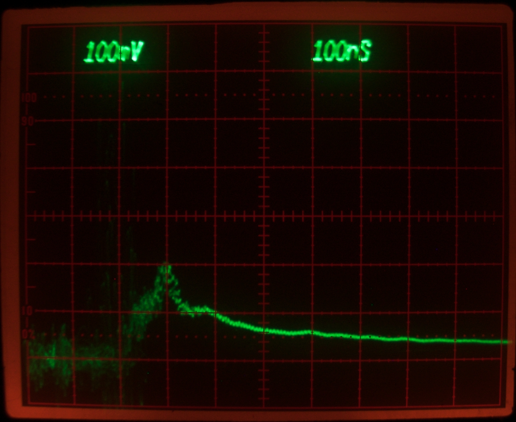
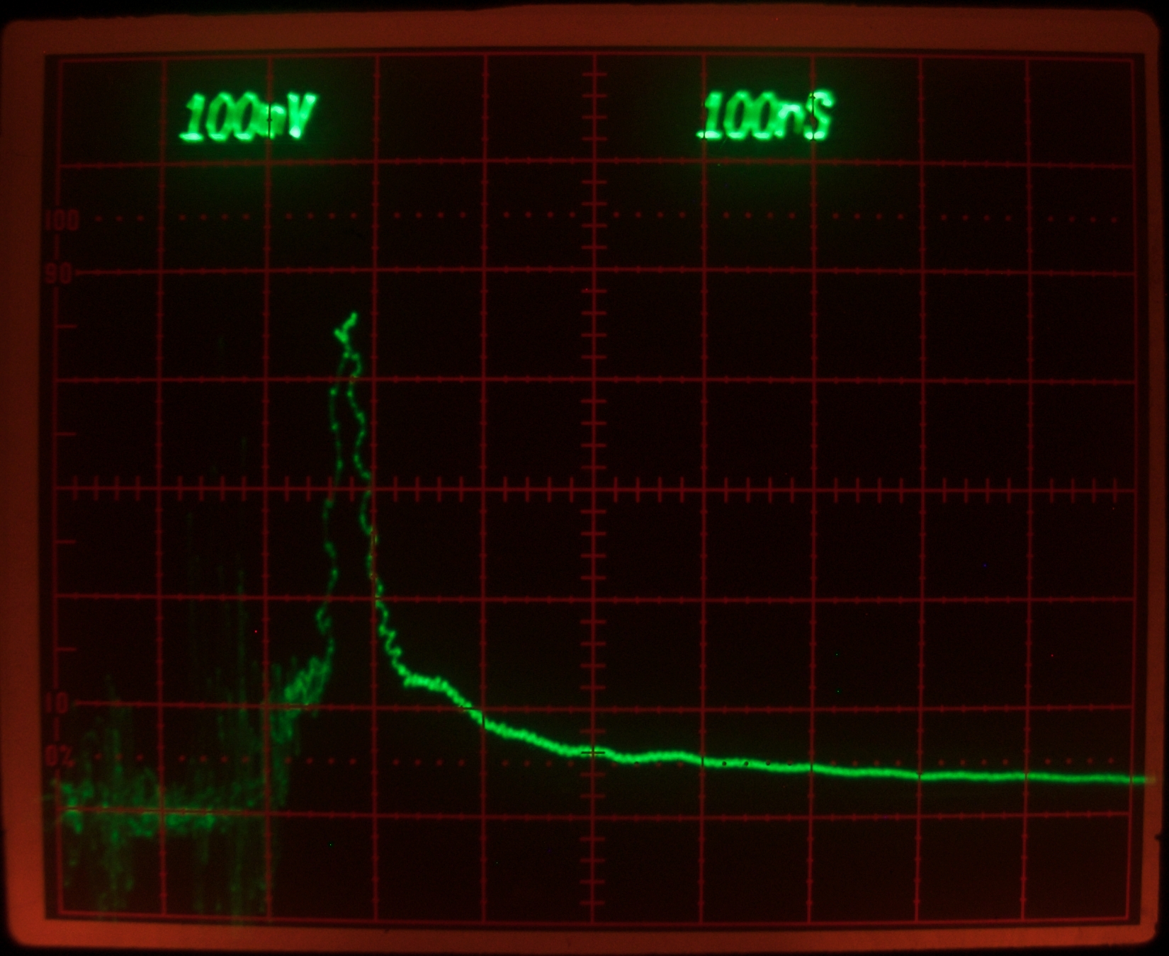
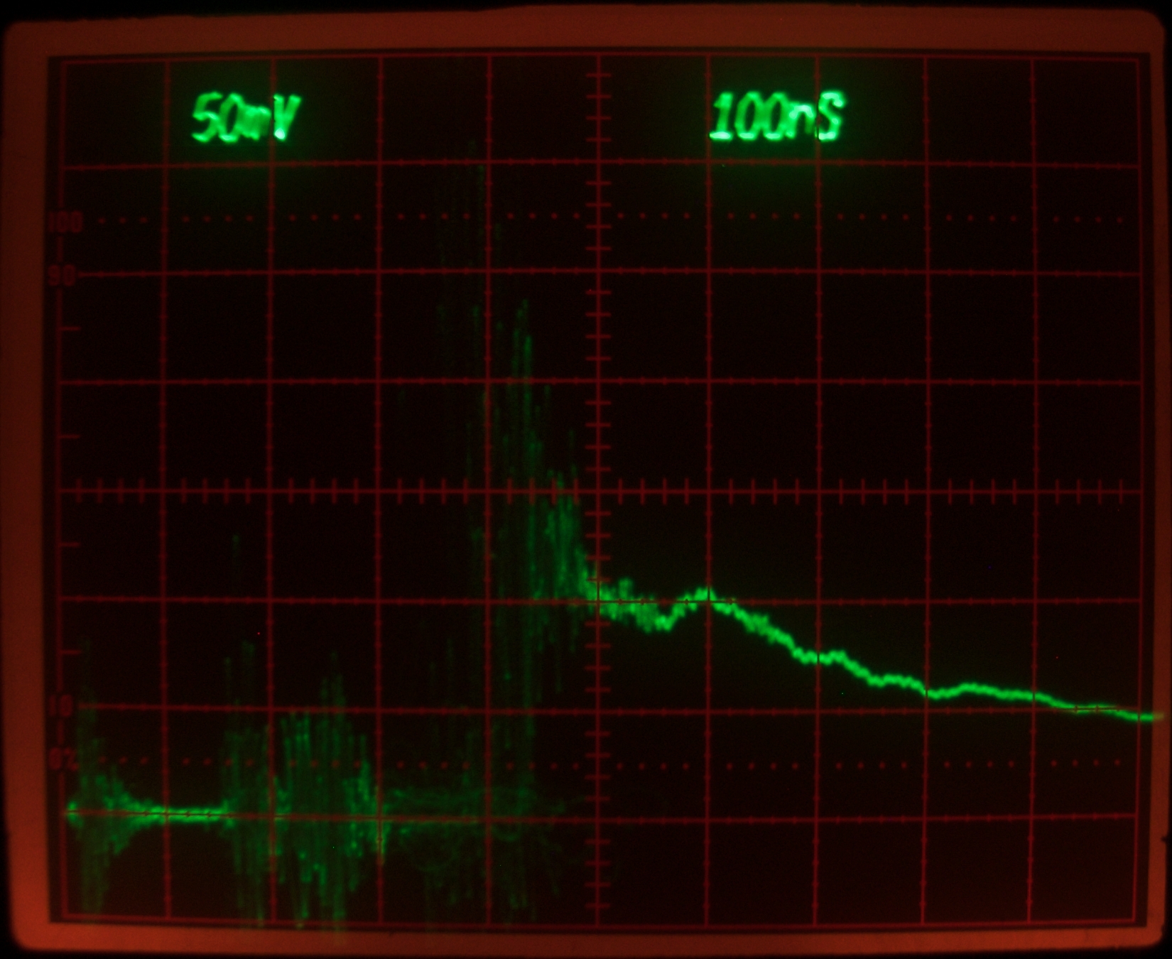
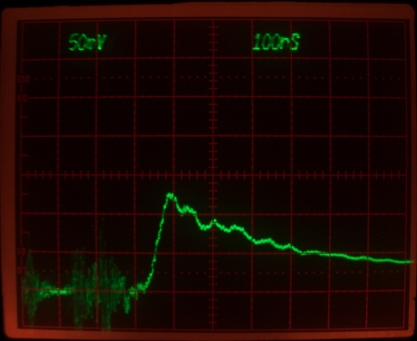
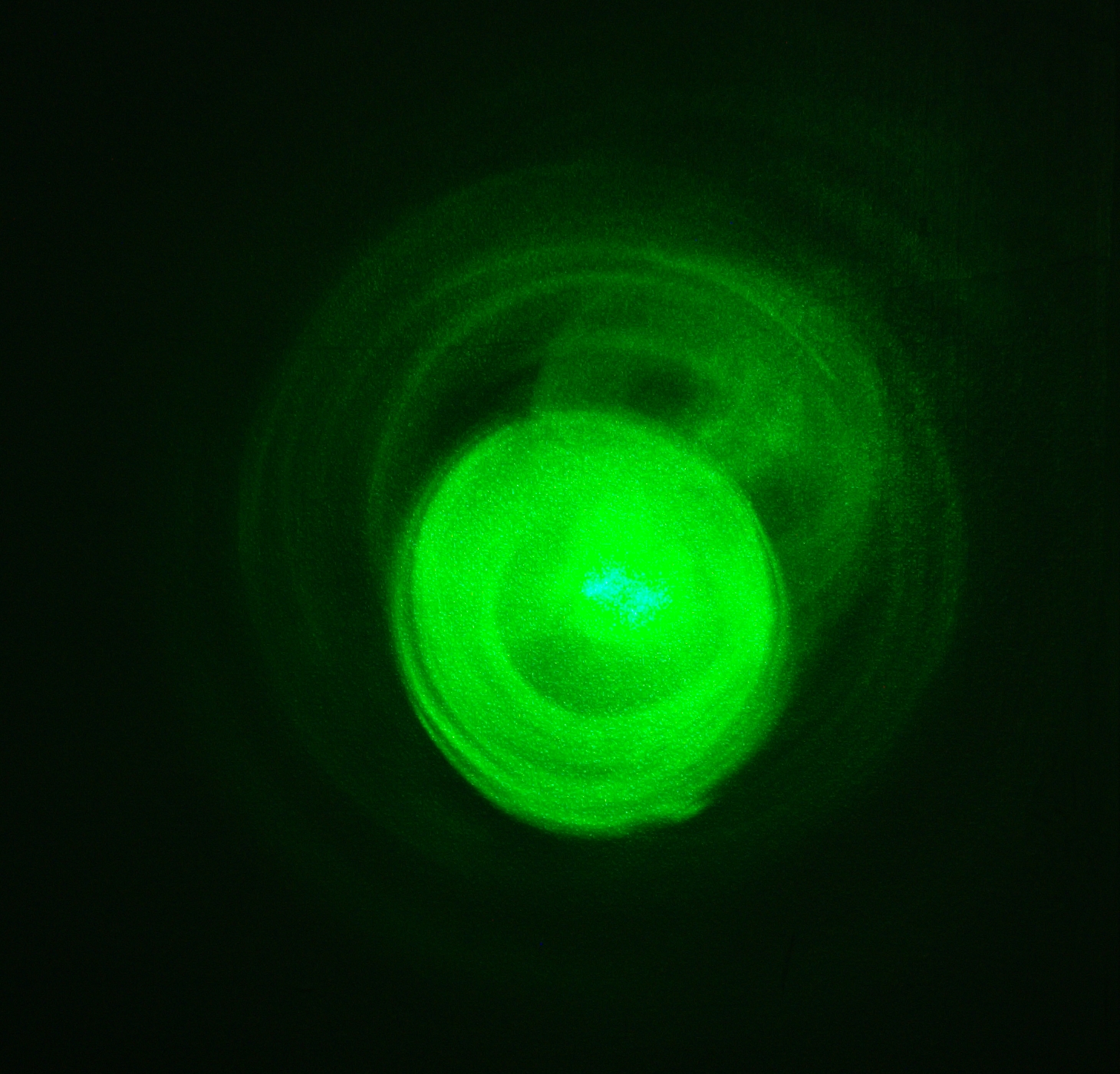
Here are three scope traces. The first shows just the
lamp output (it was taken at the point at which lasing
had been quenched); the second shows the beginning of
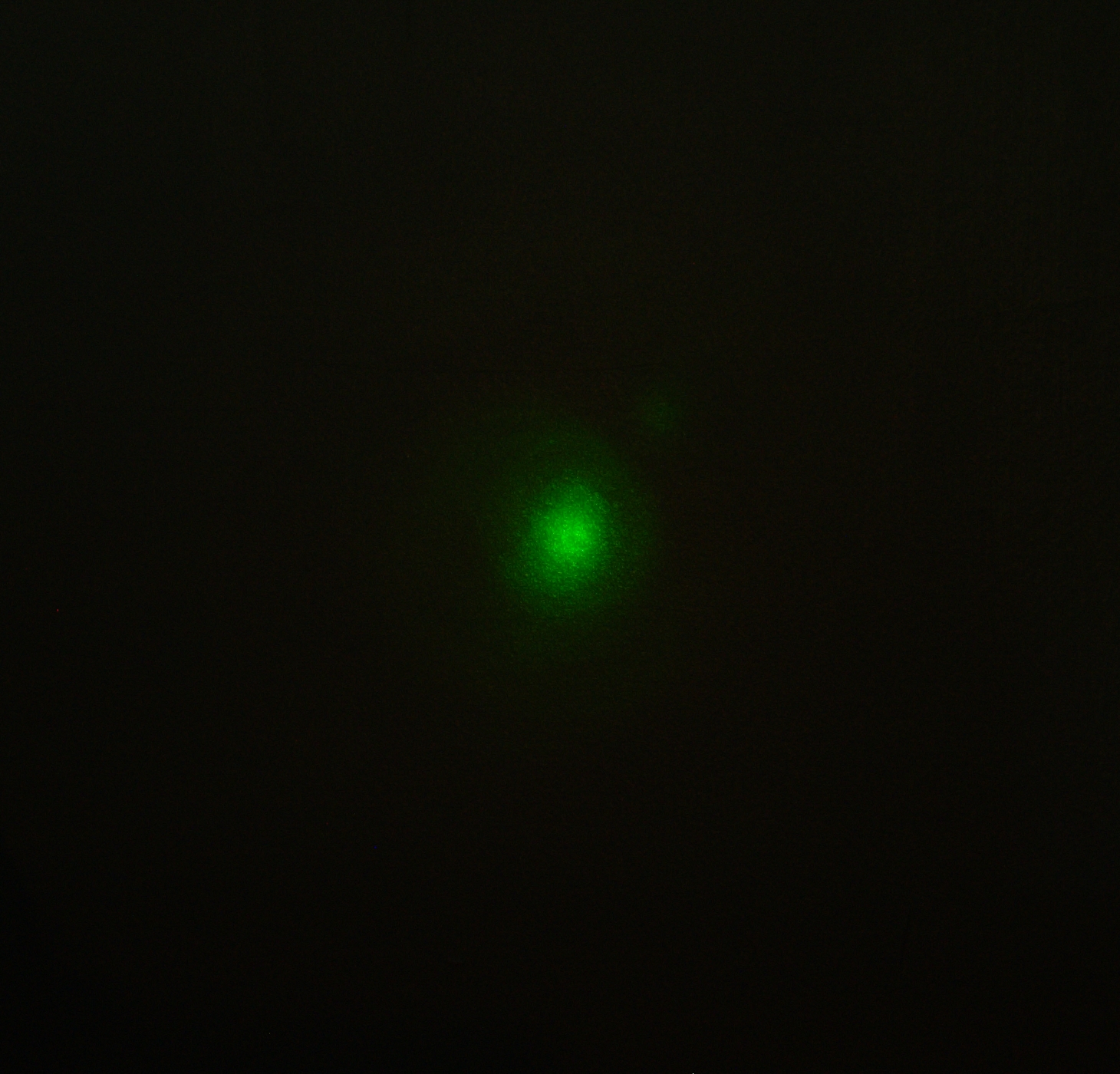
green lasing; and the third shows green lasing well
developed, as in this photo of a representative pattern
on the wall:
These traces were taken with the same settings on the
scope, and with the positions of the beam reflector and
the photodiode unchanged, so they are comparable.
Notice that in the third photo, the lasing shows one
major peak and then continues for perhaps another
100 nsec, weakly, as the flashlamp goes through its
second peak.
(later that afternoon)
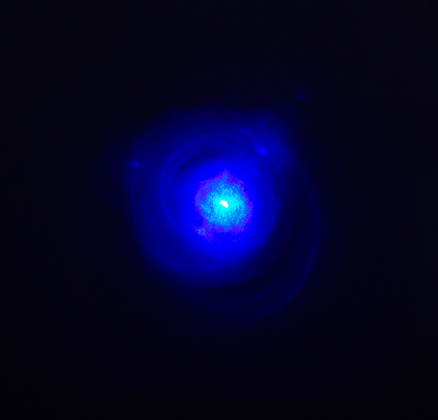
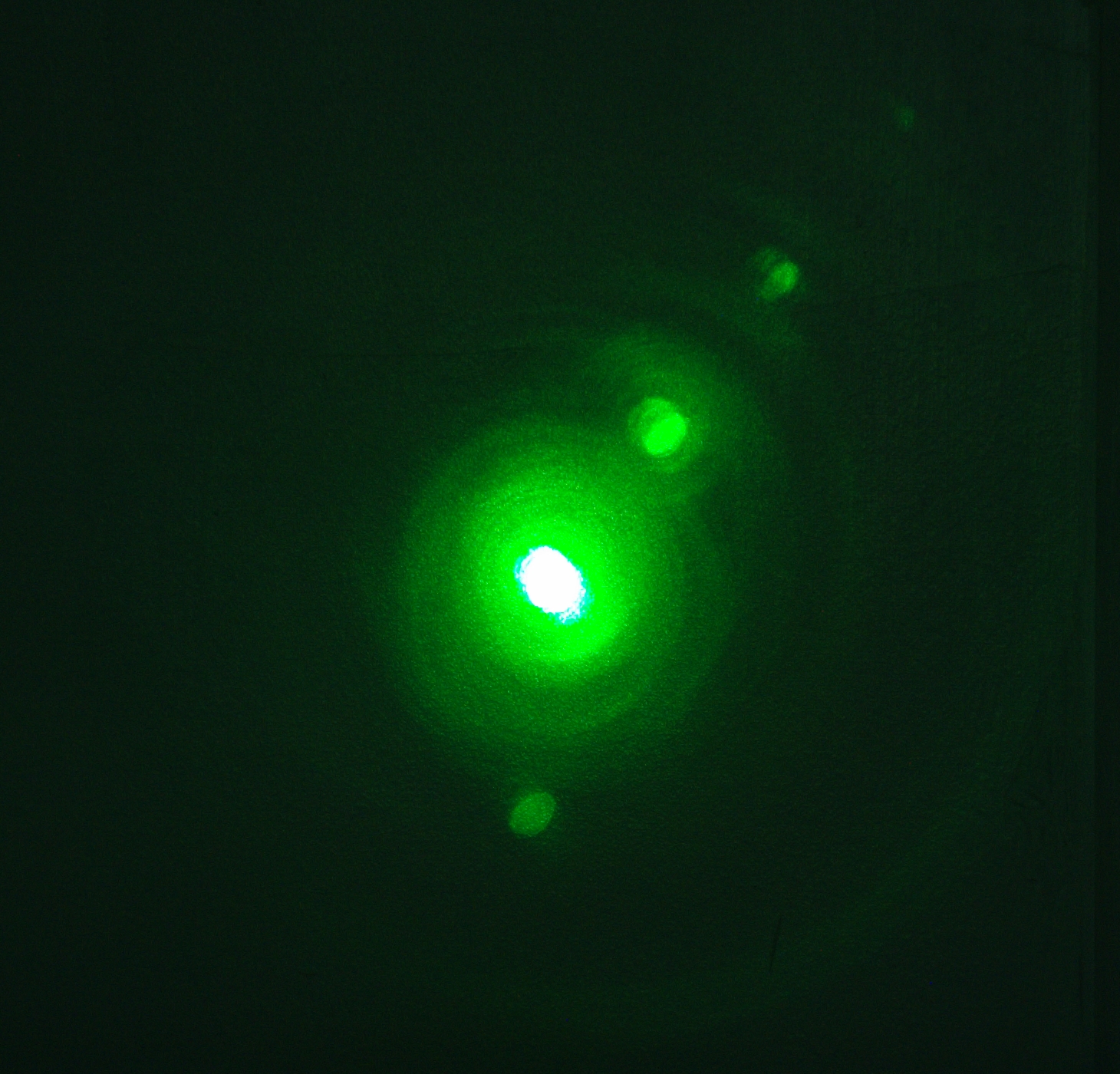
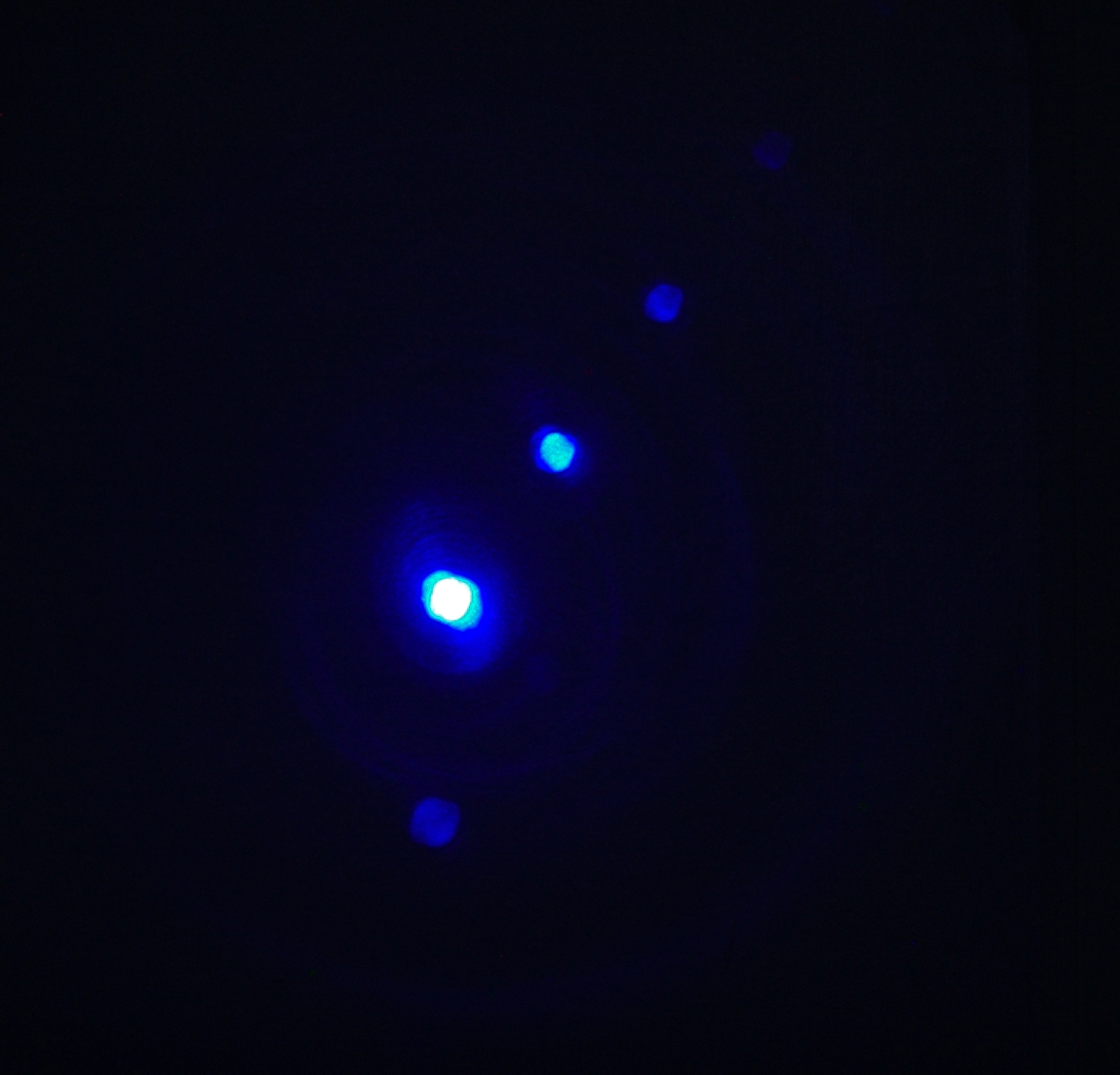
Here are some unequivocal results. In the first photo, I
have put enough Fluorol 555 into 91% isopropanol that
the laser reaches threshold. The second photo shows what
happens if I add a small amount of Coumarin 1, and the
third photo shows what happens if I add more Coumarin 1,
possibly enough that it would be able to threshold on
its own if the Fluorol were not present. (I also tried
adding a small amount of Fluorol after I took the third
photo, but it didn’t make much difference. Later I
may try adding still more; but the point is made —
Coumarin 1 definitely transfers energy to Fluorol
555 under these conditions, though it is not easy to tell
how much of the transfer is direct, and how much is by
fluorescence from the C1 that is then absorbed by the
Fluorol. Given the concentrations involved, the likelihood
is that it is mostly the latter.)
(Back to our regularly scheduled peaker cap development...
(31 January, 2010, late evening)
The 6-nf Maxwell (actually just shy of 6.2 nf) turns out
to be rated for 40 kV, so I have installed it:
I had to put lots of plastic insulation between hot points
so it wouldn’t flash over, but that worked. Here’s
a lamp trace from the oscilloscope:
The risetime looks like 70 or 80 nsec, but the system is
now underdamped. (Sigh.)
Thinking that I had perhaps added too much dye to the
solution, I poured off half of it and added an equivalent
volume of 70% isopropanol, to see how well that would
work. To my surprise, it didn’t work well at all;
the laser failed to reach threshold. I added more of
both dyes, and got some lasing, but it appears that
the mixture of Coumarin 1 and Fluorol 555 does not do
well with water in the solvent. (I suspect that this is
true of Fluorol 555 on its own, but I haven’t
tested it, so I can’t make any firm claims.)
I was just about to toss the solution and start fresh,
with a mixture of 91% and 99% iso, when I realized that
there was one more thing I could try: I added a quantity
of Rhodamine 6G. The Rhodamine was entirely happy to
cooperate. In fact, my first two traces had peaks that
were off the top of the screen, and I had to turn down
the sensitivity of the vertical amp.
This peak is only about 40 nsec wide, but that’s
not terribly surprising: the mirror is far from
appropriate for R6G, and the pumping pulse is
significantly suboptimal.
For comparison, here is a similar trace, with the
earlier 4-nf peaker (and Coumarin 1, not that it
particularly matters):
Thinking on this, I am somewhat inclined to try a larger
peaker, perhaps 8 or 10 nf. I may revise the design of
the liquid-dielectric capacitor, but I haven’t
really decided yet.
(03 February, 2010, late afternoon and early evening;
updated 04 February, 2010)
I swapped out the end windows on the dye cell for
AR-coated ones, and swapped mirror mounts in preparation
for setting the laser up with a prism, for tuned
operation. For some reason that I do not even begin to
understand, the electrical characteristics of the driver
circuit changed when I did this. The pulse became even
more seriously underdamped, and made so much electrical
noise that I was unable to see the leading edge on the
scope. The laser was just barely able to reach threshold,
and did so only occasionally. Here’s a lamp trace:
Earlier this afternoon, after thinking about the
situation, I removed the final isolation gap and got
better results. Here are a lamp pulse and a pulse from a
dye mix that is probably too concentrated. (Coumarin 1,
Fluorol 555, Rhodamine 6G; probably about 94 or 95%
isopropanol — it’s a mixture of 91% and
99+%.)
This is more than acceptable: the risetime is about 40
nsec, and the FWHM pulsewidth appears to be about 320 nsec.
I have now tested the contents of two
Sharpie™ “Accent”
highlighter markers, which I extracted briefly (no more
than a few minutes at a time) three times: first with
99.85% isopropanol (fluorescence mostly blue —
there are at least two fluorescent dyes in these
markers), and then two more times with 70% isopropanol.
The extract from these markers is initially slightly
turbid, and lasing was diffuse at first; moreover, there
is some particulate matter in the resulting dye
solution, and it should be filtered. (I didn’t
take the time.) Even so, after a bit of mixing and a
few minutes’ delay it lases fairly well:
(late that evening)
The laser is running well enough that I was able to
pulse it repeatedly and watch the pattern change; this
let me get some sense of what it was doing as I varied
the direction and speed of the dye solution, and I was
able to align the rear mirror somewhat better “on
the fly”:
Some of the glow around the bright spots may be from
particles in the dye solution, though I would guess that
most of it is ordinary lasing, with reflections off the
wall of the tubing of the dye cell, as in most of the
other photos of the far-field pattern on the wall. I
am not sure what causes the multiple spots, though.
Clearly, something slightly misaligned is
reflecting the beam, but I’m not sure what or
where it is..
Having verified the highlighter and improved the
alignment, I decided to try 4-Methyl-Umbelliferone in
70% isopropanol with a small amount of NaOH added. The
laser runs quite nicely, even with a mirror that is
optimised for green rather than blue.
I have added Fluorescein to this dye solution, and I
find that if I adjust the dye flow appropriately I can
pulse the laser more than once per second. I have not
measured the energy or power of the output pulses yet.
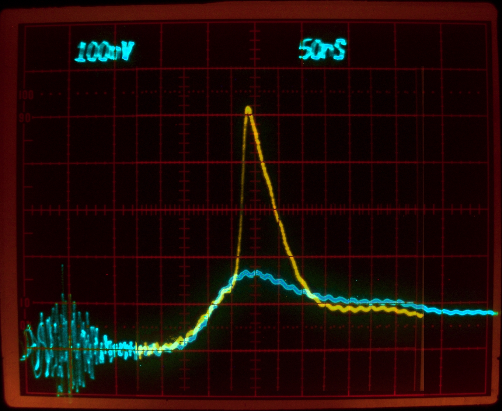
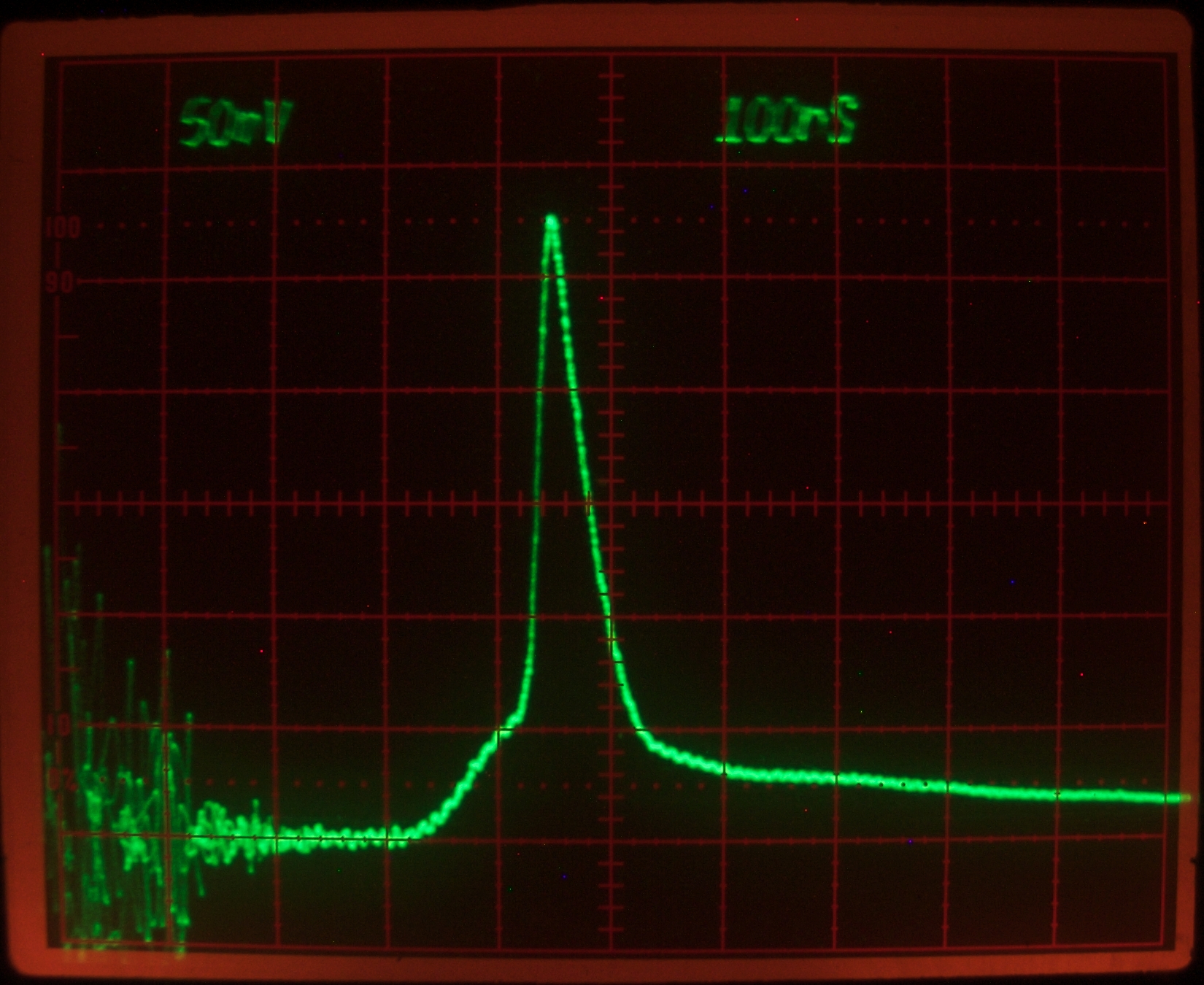
Here, however, are a lamp trace, a laser trace, and a
guess at a superimposition. Note that these were taken
at 50 nsec per division...
The lamp pulse still appears to be underdamped, and the
laser pulse is less than 40 nsec across FWHM. The short
risetime of the lamp pulse (about 40 nsec) appears to be
helpful.
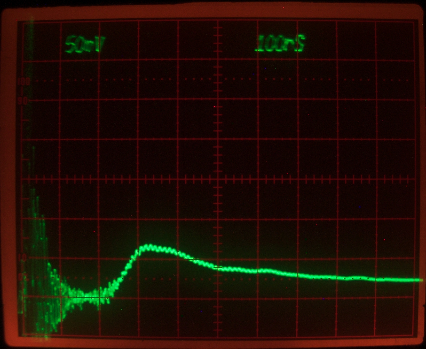
Here are the equivalents of the first two images above,
but without a peaker cap. (Everything else is the same;
I did not remove any shims, and I did not change
positions any more than I had to, just moved the ground
shims off the negative end of the peaker cap.) Note
that we are now at 100 nsec per division, not 50; the
risetime of the lamp pulse is now closer to 80 nsec than
40, and the FWHM appears to be about 440 nsec. Nonetheless,
the laser still operates. (This is the same mixture of
4-MU and Fluorescein as in the traces above.)
The laser pulse may be slightly longer without the
peaker than with it, perhaps 40 nsec FWHM instead
of 35 or so. I wouldn’t trust that, however,
as I am only showing one pulse here, and there is
some shot-to-shot variability.
(04 February, 2010)
One of the things I would like to accomplish with this
project is to move away from some of the commercial
components. Up until now, the only difficult parts of
this laser that I have actually built myself have been
the little isolation gaps. It is entirely reasonable to
use commercial mirrors, and fairly reasonable to use a
commercial flashlamp (at $16, which is what I paid for
the lamp that is currently in place, that isn’t
really any more expensive than homebrew); but the 30-nf
capacitors are about $90 apiece, which is bad; and the
EG&G or Perkin-Elmer triggered spark gap is usually
even more, when it is available at all.
I am again thinking about a Leyden jar array as the main
energy store for a version of this laser that is powered
by an electrostatic generator. It is not trivial to
build such an array with capacitance on the order of 10
nf, but it should certainly be possible. It is even less
trivial to build a Leyden jar or array with very low
ESL, but that’s an important step — if the
main store is fast enough, the laser will not require a
peaker capacitor.
(06 February, 2010, late afternoon)
The organic dye laser is in some sense the
quintessential tunable laser, particularly for the
DIYer; perhaps it is time to investigate some tuning
methods. Although a single prism does not provide much
narrowing of the bandwidth it is fairly easy to set up,
and last night I decided to try it.
Rhodamine 640 is the easiest dye to start with here,
because it can lase at 632.82 nm, the wavelength of an
ordinary HeNe laser. This means that I can align the
laser with a prism in the cavity, but no output coupler,
and actually obtain lasing, which I did. I then added a
flat OC and was lucky enough to be able to obtain lasing
again. (It was especially lucky because the OC I used is
>99% reflective at and around the HeNe wavelength, so I
had to use the reflections from the faces of the prism
as my output — I couldn’t see much of anything
coming through the “OC”.)
(07 February, 2010, early AM)
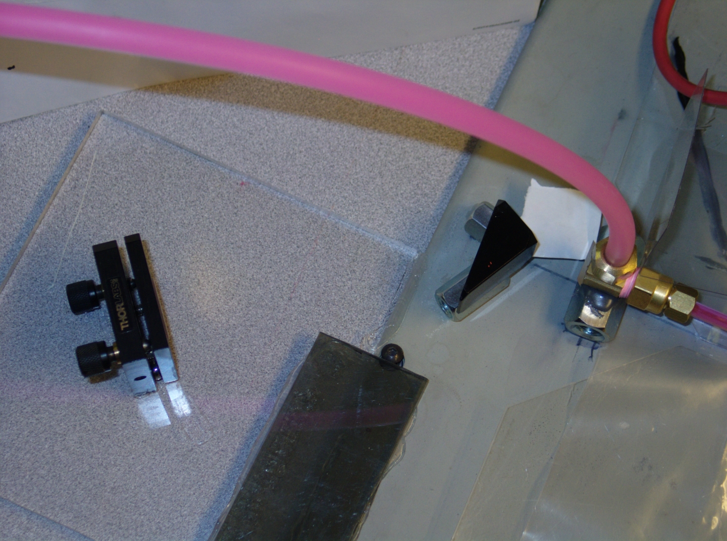
Here is the tuning setup. The prism is just off the
end of the dye cell, and the mirror is to the left.
The back of the prism is painted black; I’m
not using it. The other two faces are AR-coated,
which lets me rotate the prism to any angle I want,
instead of being constrained to Brewster’s
Angle or the angle of minimum dispersion (which is
close to Brewster’s Angle).
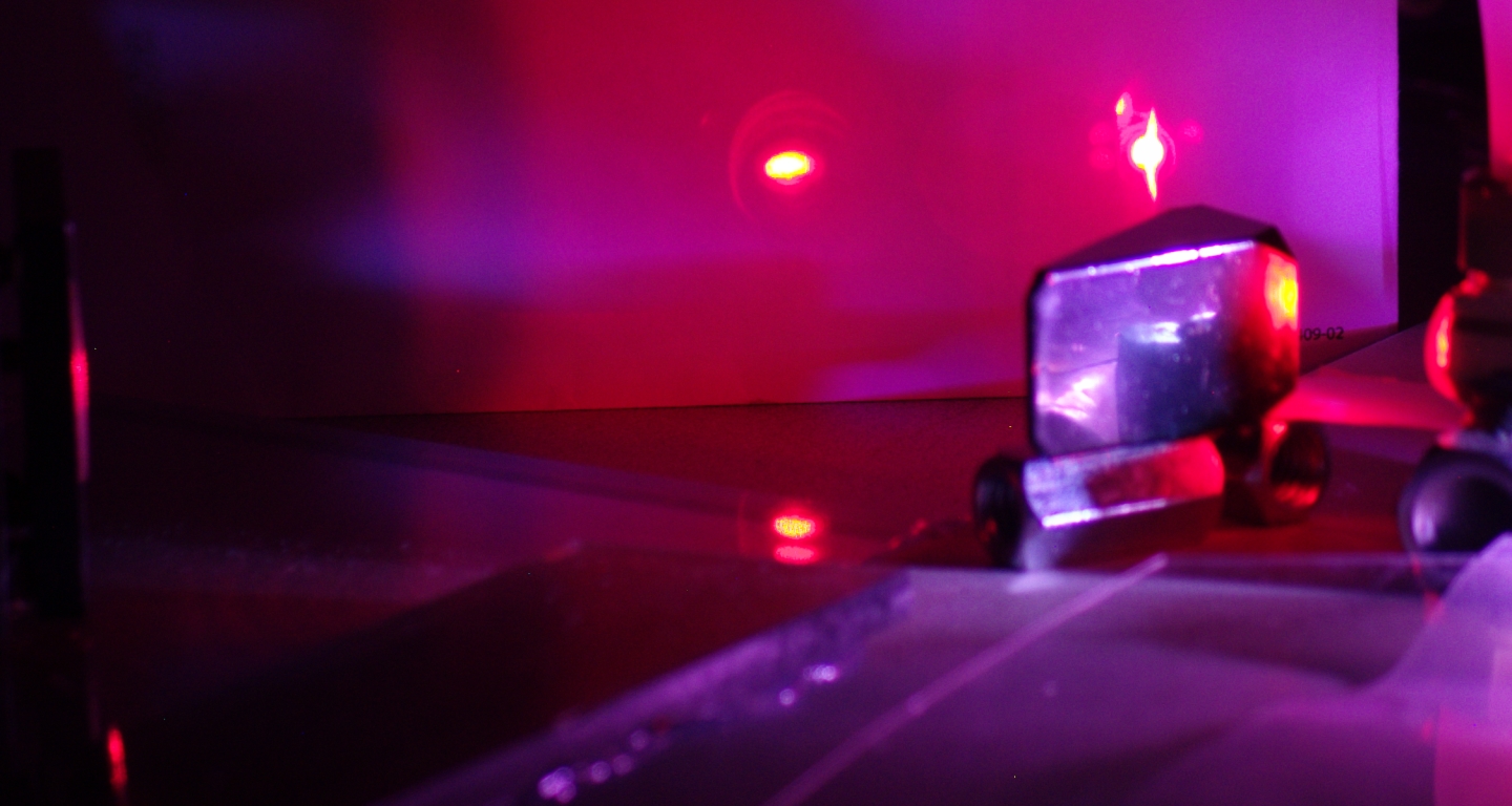
Here is a photo, showing the laser running. It is not
possible to see any tuning effect in a single image, and
of course I will have to run the output through a
monochromator to find out how far I’m able to tune
the dye, as my eyes are not calibrated in nanometers. At
least the photo will give you a sense of what this setup
looks like when it is in operation.
Note the fact that even the reflection of the dye cell
off the black paint on the back of the prism is bright
enough that it begins to overdrive the sensor of the
camera.
(10 February, 2010, late evening)
It is obvious that the prism needs to be mounted
securely in order for this to be more than a mild
amusement. The problem is that we need 3 axes of
control, and an ordinary mirror mount provides only
two. I am lucky to have an older Quantel mount here that
allows me to fake the third rotational axis because of
the way it holds its optic. (I will try to provide a
photo when I have a chance to take and label one.)
The two important adjustments of the prism are:
A) The top of the prism tilts toward or away from the
mount (this is the regular vertical axis motion),
The horizontal axis motion of the mount is considerably
less important, as I have set the prism in a reasonable
orientation. Under other circumstances I might want to
set the prism at the angle of minimum deviation, but
this prism has AR-coated faces, so that really
isn’t an issue here.
I am now attaching the mount to the base, and the prism
to the mount. When the RTV has had a chance to set
I’ll try aligning things, and we’ll see how
far I get. With some luck I will be able to tune other
dyes, which I can’t easily do as long as I have to
make adjustments to the vertical axis of the rear mirror
in addition to the tuning (which is done with the
horizontal axis).
(13 February, 2010, early afternoon)
After tweaking the alignment and making a series of
tests, I have concluded that this laser would be tunable
only if I had a dye pump on it. Short of that, it can
be fired only a few times per hour. I have removed the
prism, and restored the laser to its previous configuration.
I may post some illustrative photos here.
(13 February, 2010, early afternoon)
Jarrod Kinsey
builds electrostatic generators, and he has also built
quite a few TEA nitrogen lasers. When he first contacted
me, he asked me whether he could use an electrostatic
generator to power a nitrogen laser, and I told him that
it would work just fine. (At that point, he told me that
he had asked several other people, all of whom had told
him that it was a dumb idea and would never work. I
strongly suggested that they had not thought through the
issues carefully enough, and that they were wrong.) He
tried it, and it did work. It is now several years
later, and he wants to build a flashlamp-pumped dye
laser, which is how this project got started: he asked
me what it would take.
The first question has now been answered: a reasonably
fast system can threshold at least some dyes with only
6 J stored in its main capacitor (or capacitor bank),
but 10 or 12 J is better if you can get it.
I take a look at the next question on
the next page in this set.
Back to the first page of this set,
which covers the initial design and development of the laser.
Back to the second page of this set,
which covers the first set of refinements.
My email address is a@b.com, where a is my first name
(jon, only 3 letters, no “h”), and b is joss.
My phone number is +1 240 604 4495.
Last modified: Thu Jun 23 15:54:26 CDT 2016
2: Construction


Sidebar: Energy Transfer
3: Next Steps
Sidebar: Tuning
and
B) The long pointed end of the prism moves up or down
with respect to the shortest face. (This is the rotation
I mentioned above.)
4: Leyden Jar Main Store
This work is supported by
the Joss Research Institute
19 Main Street
Laurel MD 20707-4303 USA
Contact Information: