[Work continuing from
Broadside #5]
(2013.0522 &ff)
Now that I have a beam I can depend on for long enough to expose a film or plate of modest size, it is time to try making use of it. I am going to build an extremely simple and very small holography setup, and direct the beam into it.
Because the film I have is very old, and because the wavelength I’m using is relatively short, I think I will go for a fairly small angle between the reference beam and the object beam. I am also going to keep the pathlength differences small, at least initially.
[Note, added late evening 2013.0605: I checked, and the film, which has a 10E75 emulsion, has average grain size of 90 nm. That’s a bit large for ~400nm light, and I’m not sure whether it will be viable. I do, though, have some badly outdated BB plates that are sensitized for use with green light, and those are more likely to be suitable if they are still in good enough shape to work; the average grain size is probably about 20-25 nm, and the limiting resolution is significantly higher.]
(This section added 2013.0604, very late evening; and 2013.0611, early AM; note that some of what is described here postdates material that appears further down on the page.)
It turns out that as long as the laser has enough coherence length and does not mode-hop during the exposure, it can move around without ruining the hologram. This makes it convenient to have the laser on one platform and the holography setup on a different one. After the beam reaches the beamsplitter in the setup, however, the requirements are quite stringent. If anything in the setup moves more than perhaps 1/10 or 1/8 wavelength with respect to anything else in the setup, the hologram begins to lose contrast. Much more motion than that, and you won’t get much of a hologram, if you get one at all. It should come as no surprise that getting something to move 50 nanometers or so is far easier than preventing it from moving.
I went up on the Web, and read a bit about this general kind of stabilization. It seems that there are at least two main approaches: preventing the setup (usually the base) from responding to vibration that is present, and damping out vibration to prevent it from reaching the components in the first place. [No, not “dampening”; to dampen something is to make it wet. You dampen someone’s ardor by raining on their parade, and you dampen or moisten a cloth if you want dust to adhere to it; but you damp vibrations and oscillations. It is possible to damp or dampen a fire, but dampening it is usually a way of making smoke, or an attempt to put the fire out; damping a fire slows it down and lets the fuel last longer.]
There are several approaches to this set of issues. If you make your platform very massive, it will have a low resonant frequency. This tends to prevent vibrations and motions of low and moderate frequency from disturbing your setup; if you are lucky, motions with extremely low frequency will just cause everything to move in concert, and won’t be a problem unless those motions are part of an earthquake, in which case the hologram tends to assume secondary or tertiary importance. Ahem.
Having a base with low resonant frequency does not necessarily prevent vibrations with significantly higher frequency from reaching the components, but it should decrease their amplitude at least to some extent. If you can then make everything in the setup that sits atop the base stiff and tightly coupled, so that the parts move in concert if they move at all, you have a reasonable chance of success. I don’t have the option of putting a ton of granite into my basement, so I am obliged to take a different tack.
It is possible to absorb some vibrations, and turn their energy into heat. Various materials are used for this; one of them is a gloppy polyurethane rubber composition called Sorbothane®, which is fairly effective and readily available. I have incorporated four hemispheres of it into the stack, as I mention below. I am also using nylon yarn, as I mention below, along with two fairly heavy slate tiles and some soft plastic foam. My reasoning, which I will admit is somewhat loose, is that if different layers in the stack have different resonant frequencies and at least some of them are only loosely coupled to each other, the combination can (and, I hope, will) have fairly low Q over a relatively broad frequency range. That is, if something does disturb the base, the resulting motion at the top will be slight, and will stop very quickly rather than continuing to oscillate. As you will see from one of the videos I link to below (the one from June 9th), this approach appears to be at least marginally viable. Whether it will actually permit me to make holograms, though, remains to be seen.
(2K14.0126, late evening)
At a thrift store, earlier today, I got a bunch of hair-curling things that are essentially little steel springs wrapped in gauzy fabric. When I have time I’ll see whether an array of them can contribute to stability.
(2013.0529, late evening)
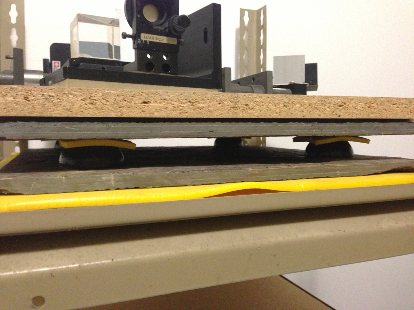
A bit earlier I threw together a Michelson interferometer on the table that I hope to use as a holography bench. I haven’t done much to this platform yet, and I figured it wouldn’t be very stable. It lived up to that expectation quite thoroughly. Here is a video [handheld again; my apologies for motion] of the fringes from it, with a good clean contrasty pattern from the main Michelson (not shown). I am now thinking about ways to stabilize the platform... I went up on eBay and bought four hemispheres of Sorbothane, each of which is 2" across. They arrived this afternoon, and I took a few minutes to make a quick test setup. As a bit of an assist, I included two large square tiles of slate. The stack order, from the bottom up, is: shelf; soft yellow foam; slate; Sorbothane; soft yellow foam (one smallish piece on top of each hemisphere); slate; a thin piece of cloth; chipboard:
(The thin cloth is not visible in the photo; it is in the dark gap between the upper slate and the chipboard.)
Here is about 15 seconds of video, showing the result. I will note that the platform is still very sensitive to vibration; but if I don’t move around and there isn’t any traffic, it will probably do. Mind you, I will probably add more layers to the cake anyway, as every little bit helps, at least if it’s the right little bit.
(2013.0605, late evening)
I took another look at the pattern, this time with the clothes dryer going in the next room. The platform is definitely not sufficiently stable to handle that, but I didn’t expect it to be. I am thinking about adding some beanbags, and I have set up my sewing machine; but it is clear that I am not going to make bags from old socks with this machine (that would take a serger, or perhaps cotton socks rather than the usual knits), so I have to find something suitable, or go to G Street Fabrics and buy a small chunk of something.
An alternative: I have a small hot-water bottle, a little rubbery thing, which I have just filled with lentils as a quick check. It seems like it would do, but one is not enough; if I go this route, I will have to find two more at thrift stores.
(2013.0607)
I tried making up plastic sandwich bags with ~200 grams of lentils in them, and putting 3 into the stack. That actually seemed to make things worse, so I took them back out. I still have extra layers in place, though, to set the height so that the beam goes into the Michelson. The pattern jumps around when the laser mode-hops, but is otherwise reasonably stable when there’s no particular vibration in the floor. (Photo/video when I get a chance.)
(2013.0608)
Last night I added three small stuffed animals (an anteater and two rhinos) to the proto-holography platform, to see whether that would help stabilize it. Results inconclusive, but I don’t think it’s any worse.
Also last night: while I was tweaking the laser setup I accidentally bumped the prism, and was surprised to notice that the laser remained locked even though the secondary beam was no longer going into the Michelson. I continued to tweak, and found that although the behavior without the interferometer is somewhat different, it doesn’t seem to be any worse; the etalon alone appears to be sufficient to coax the laser into running on a single longitudinal mode.
I then took a look at the positioning of the focal point of the collimating lens. Once again, it became entirely clear that this makes or breaks my ability to lock the laser. (I will admit that it annoys me to have to be reminded of fundamental characters of what I’m doing, but that’s life.)
Without the Michelson, I have to have some other way to tell when I have enough coherence length. Fortunately, the two-plate method that I learned from Milan Karakas (which he assures me he did not invent) is suitable. If I use an AR-coated window as the first plate, I will lose only a few percent of the beam power, which is tolerable. A few milliwatts should be enough to make a visible test pattern on the fluorescent screen, and this should be very easy to test...
(that afternoon)
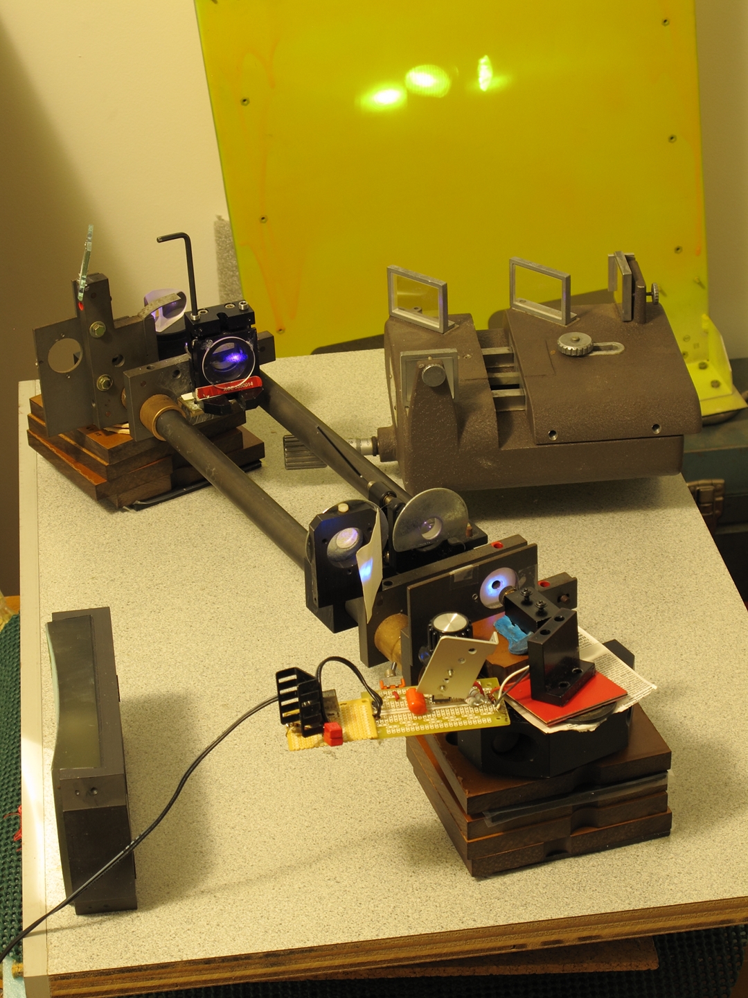
Here is the new setup, with a typical pattern. (You can just see the edge of what will become the holography table at the top left corner of the first photo.)
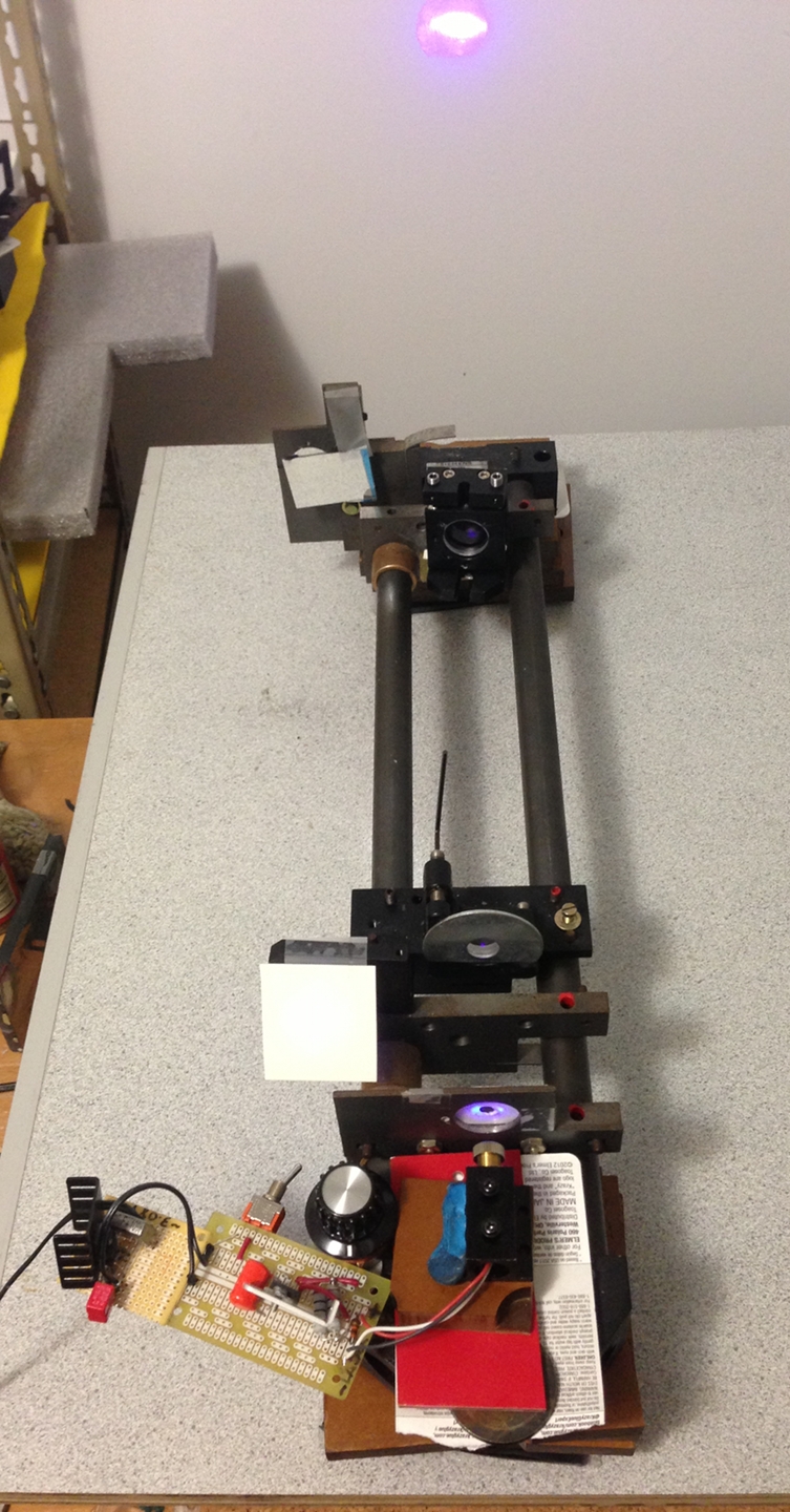
The pattern, which is currently indicating coherence length of more than 25 cm, seems to remain stable for as long as it did with the previous setup, which is more than long enough.
(late that night)
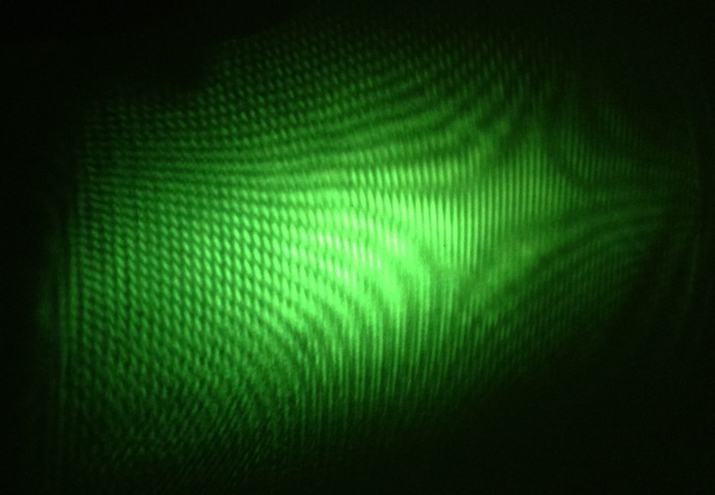
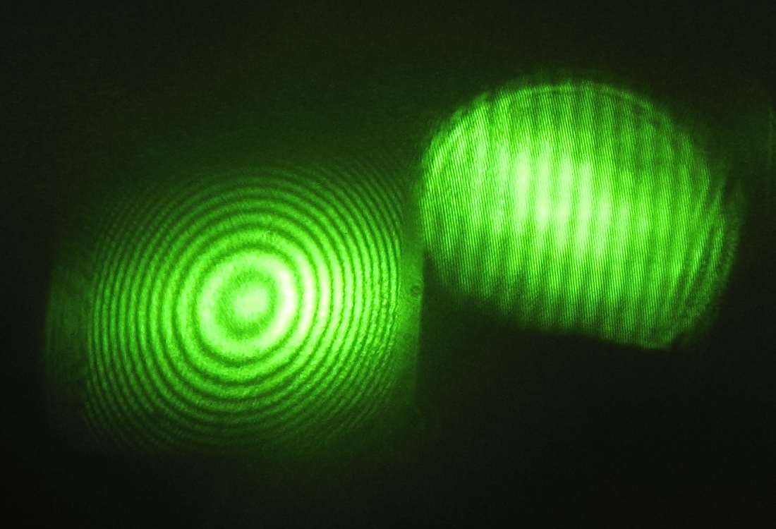
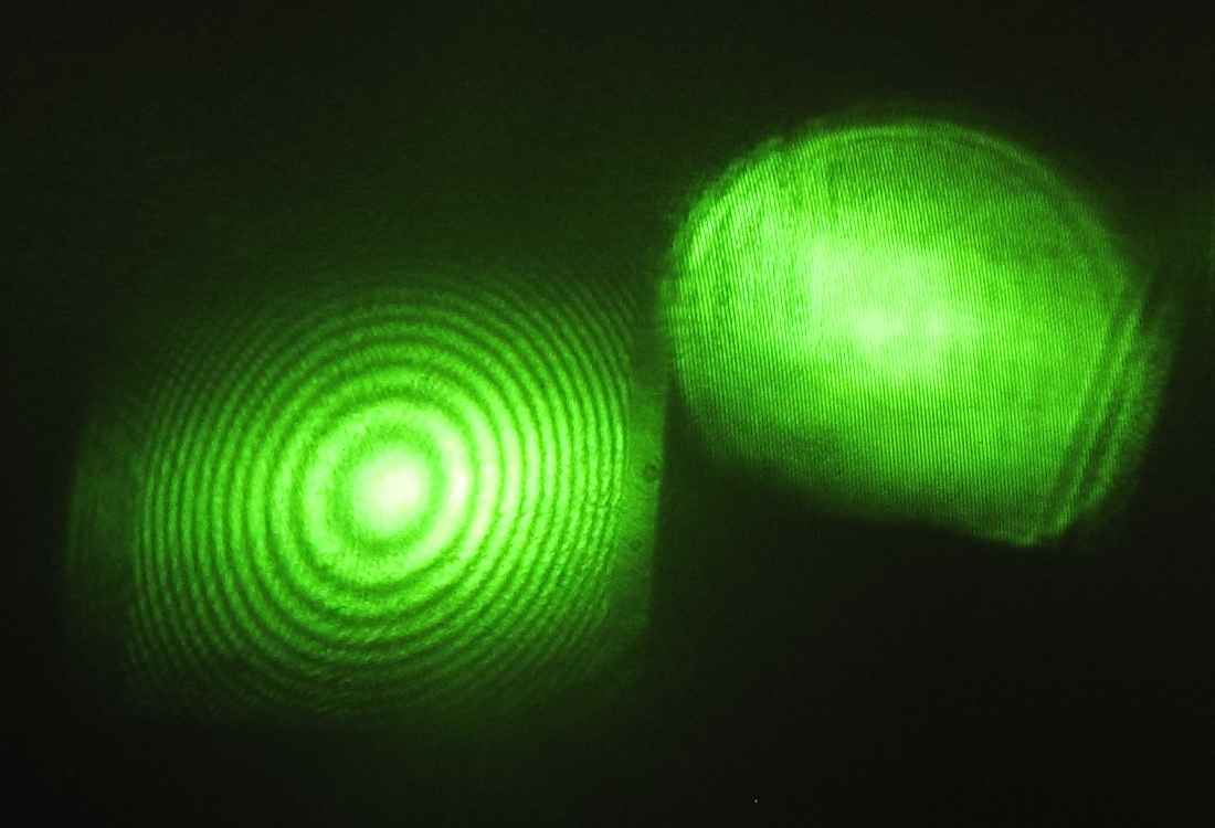
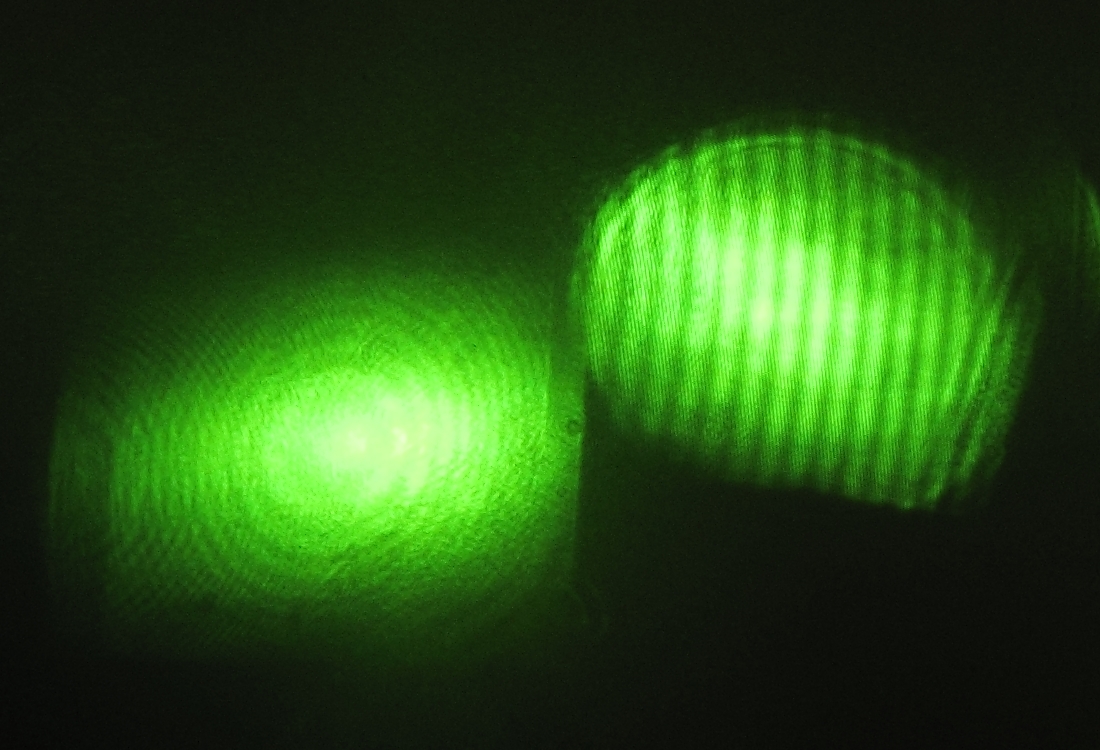
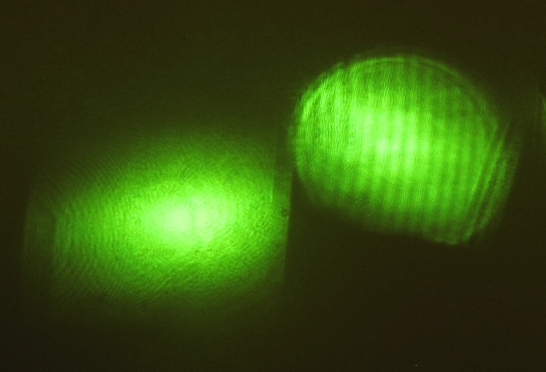
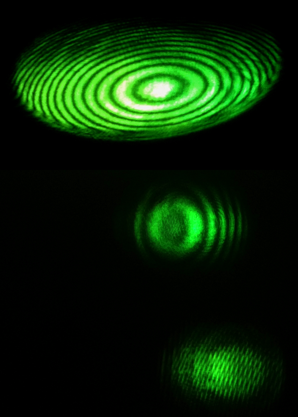
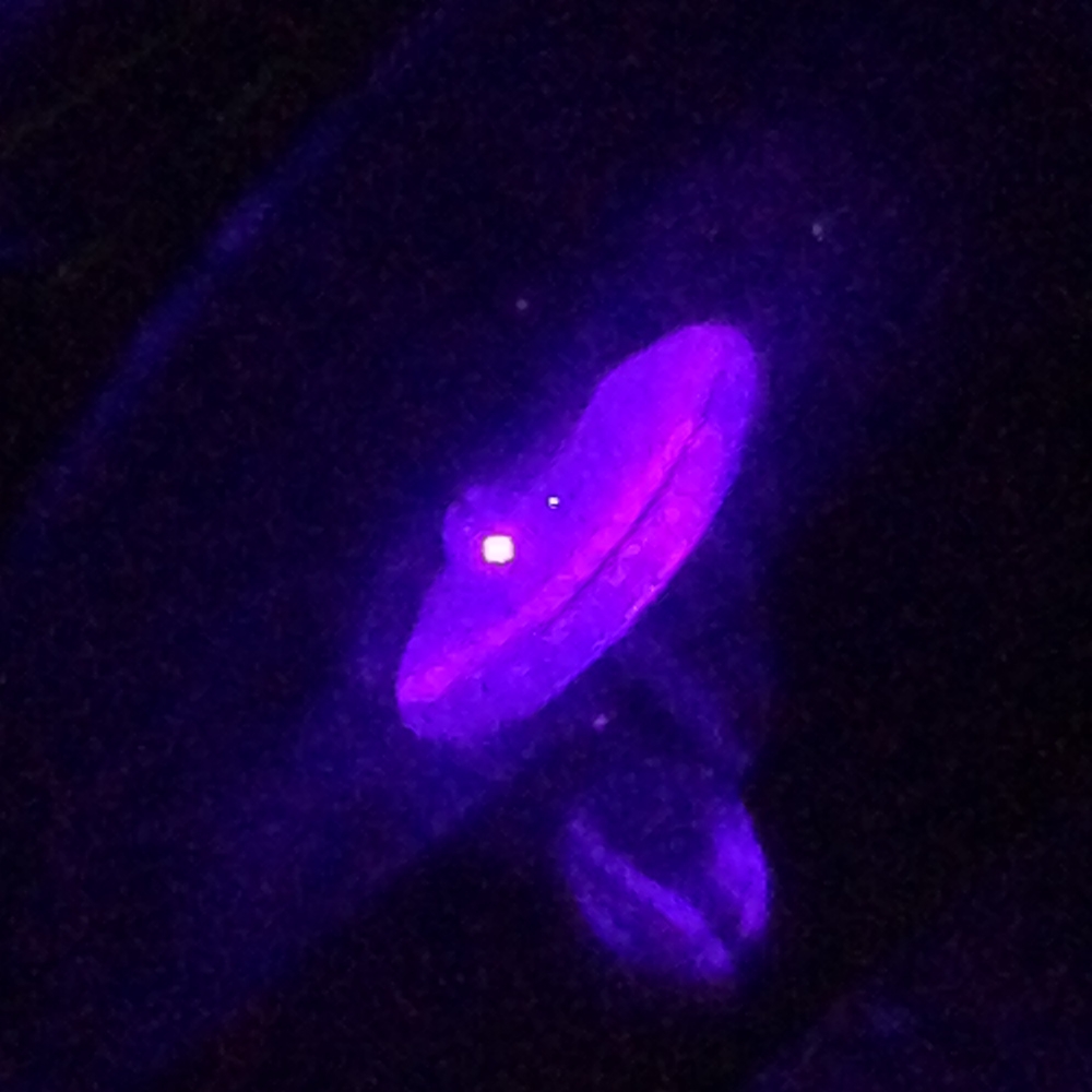
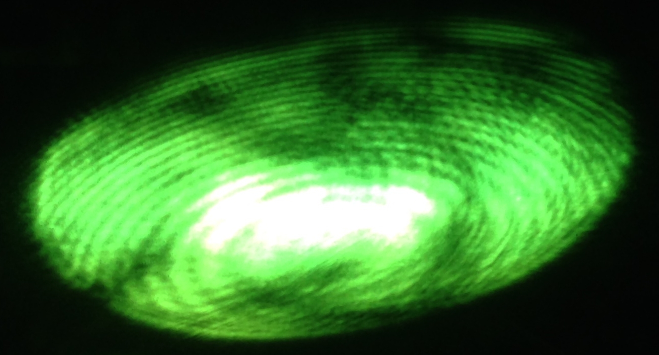
I have changed the coherence-length check, replacing the sewer-camera window with the coated etalon. I am, at least most of the time, using a lens to enlarge the pattern for viewing. Here are three images that show the pattern with several longitudinal modes running (but still with enough coherence length to get stripes from the first test plate), then with diagonal stripes just starting to be visible, and finally with the laser apparently running on a single longitudinal mode:
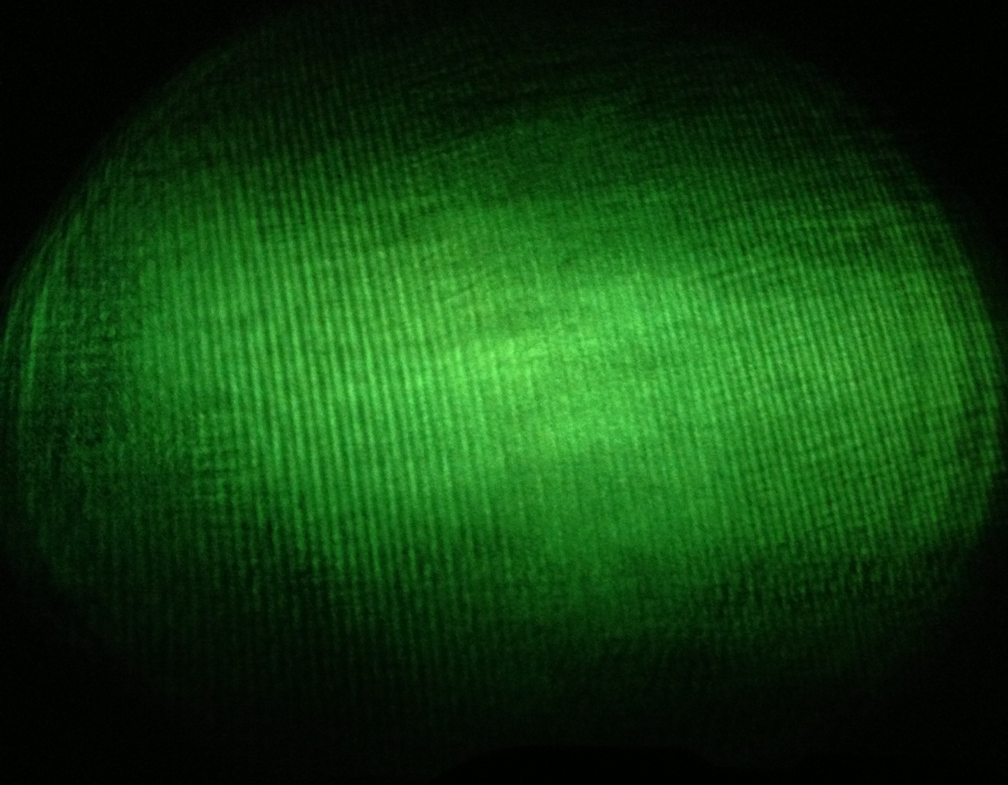
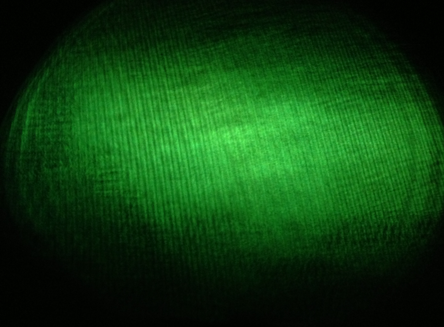
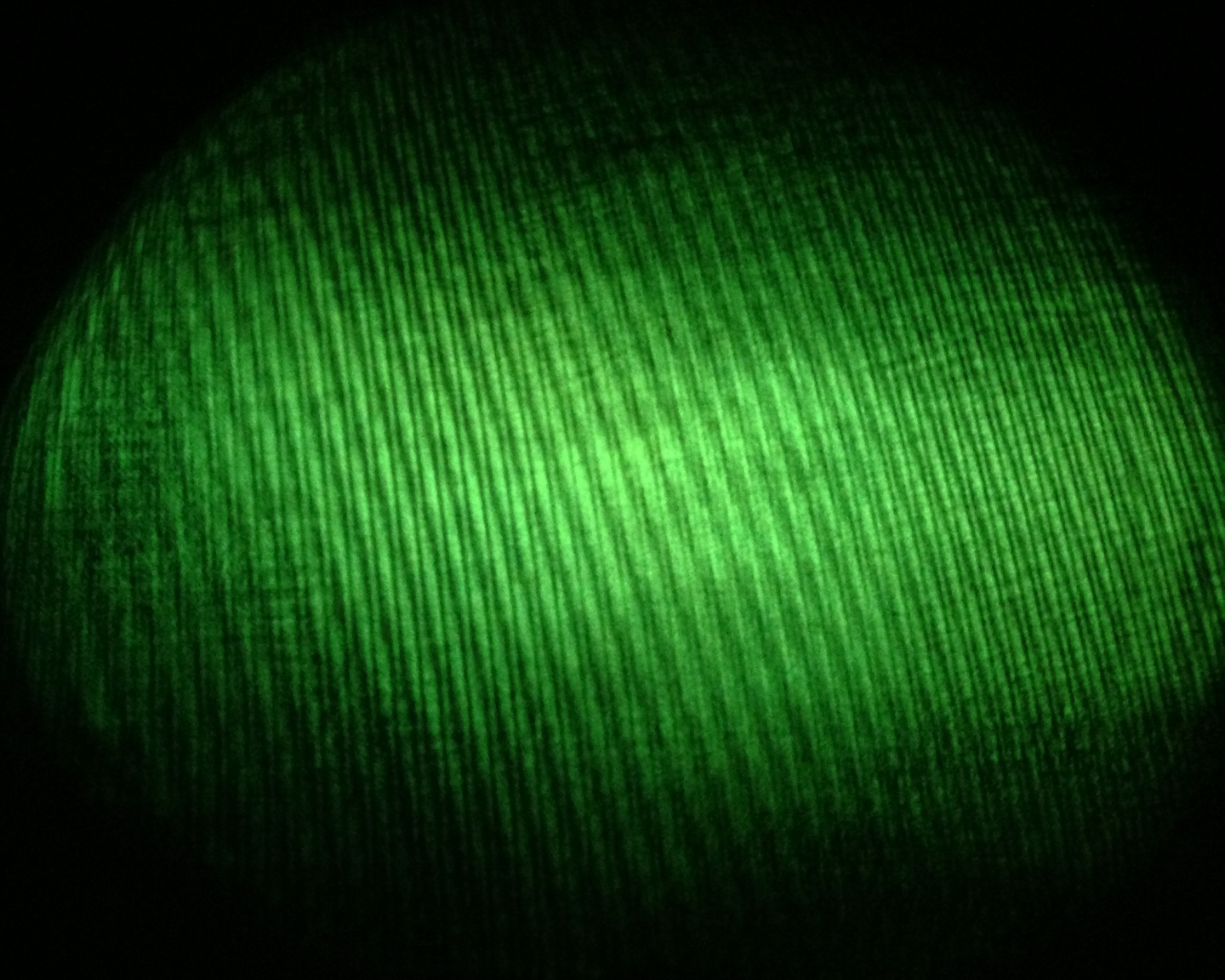
(I do not yet know why the center of the pattern is blurry; I hope that it isn’t anything fundamental about the beam. Fortunately, the fact that stripes are visible through the blur in the third photo suggests that it’s an artifact.)
(revision for stack change and new video, 2013.0610, early morning)
I took out the stuffed animals this evening, and swapped in six wads (I am not thinking of a better word; “skeins” is technically correct, but these don’t look as well-ordered as anything I would ordinarily describe by that term) of nylon yarn that I bought at a thrift store this afternoon. They are very fluffy and rather squishy, and they seem to help keep the vibration sensitivity down a little. As with the erstwhile stuffies, I put a piece of the soft yellow foam on top of each of them before setting the square of chipboard on them. Here is a side view of the stack as it is currently configured:
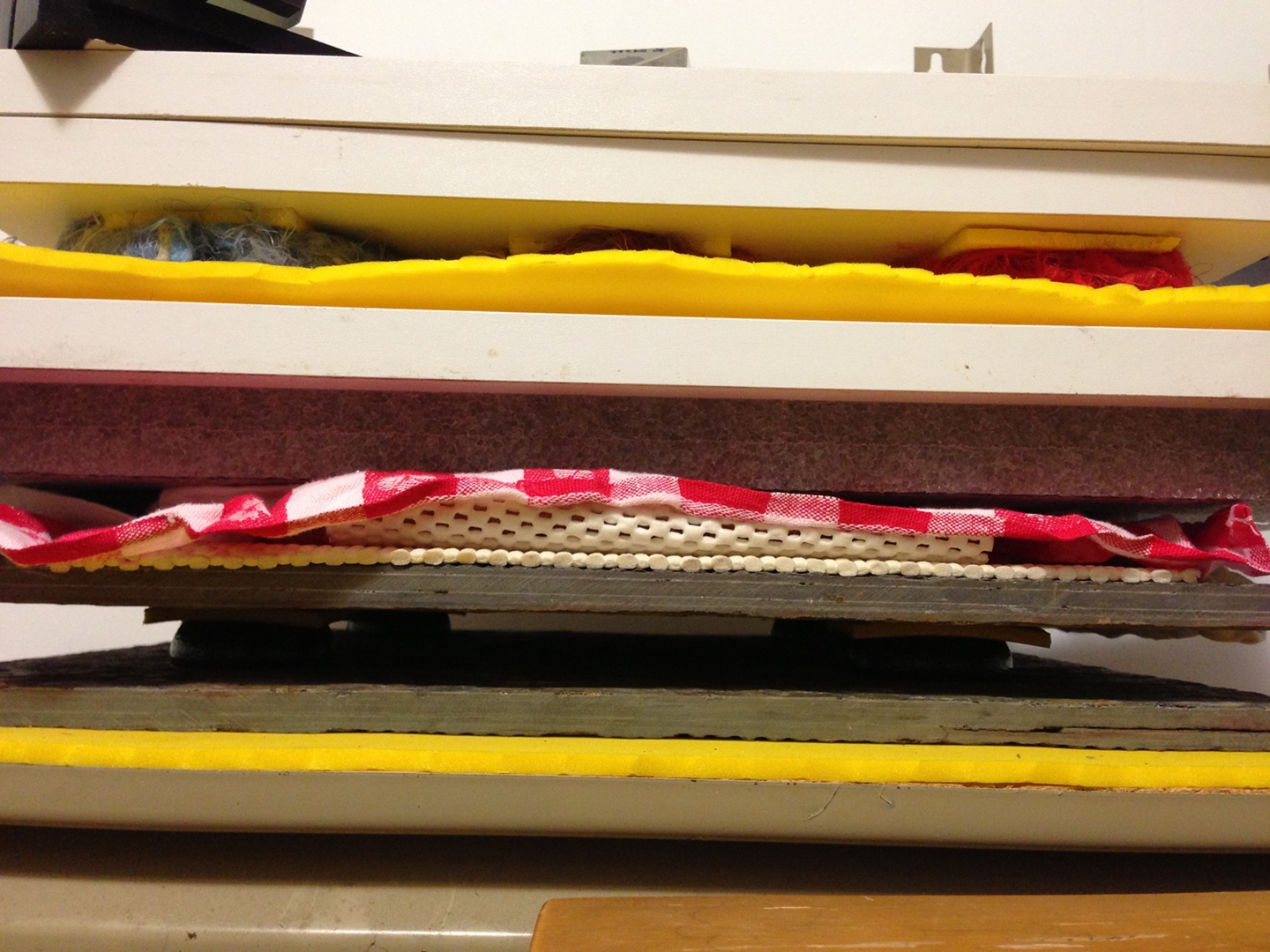
From bottom to top:
Here is a video, showing about 27 seconds of reasonable stability from the platform, except when I stamp my foot. (Filesize a bit less than 25 MB.) The coherence length, as judged by the contrast of the fringes from the Michelson, was stable for a little while before I started the camera, and remained stable for at least a little while after I stopped filming. (If the laser mode-hops, the pattern from the Michelson dances around like crazy. If the laser starts to oscillate on a lot of modes at once, the fringes blur out.)
(2013.0609, afternoon)
Last night at dinner, Amanda Lwin made a rather magical suggestion about the anti-vibration stack of the holography platform. I will attempt to implement it, and I’ll provide photos here if/as that happens. It may be a while; the things I need for it are not as easy to find as I had hoped.
(2013.0613, late evening)
In order to make holograms on this setup, I will need a protective housing around it to exclude stray light and air currents. I have made the four wooden pieces that will be the framework of the housing; they are quarter-square wood molding, and they have mitered ends so that they will sit nicely on top of the vertical posts of the Gorilla Rack after I attach them to each other. I suspect that I will use heavy card stock for the roof, to keep the weight down; either I will buy a sheet that is black on one face, or I’ll paint it matte black with spray paint. The side curtains of the housing will probably be made of the same material as the roof, possibly excepting the side where the beam enters — I will need to be flexible about this, so I may use thin plastic sheet (perhaps several layers, for better blocking of stray light) on that side.
(2013.0615, early AM)
A different opportunity presented itself, and I took it: I found one of those 18x24" corrugated-plastic signs, of the “YARD SALE” variety, cleaned the dust and cruft off it, and spray-painted it flat black on both sides. I want about a 20" square, so I cut an 18x20" rectangle from it and made the remaining 2x2" edge from what was left. I used cyanoacrylate to glue pieces of wood to the back, to hold the assembly together.
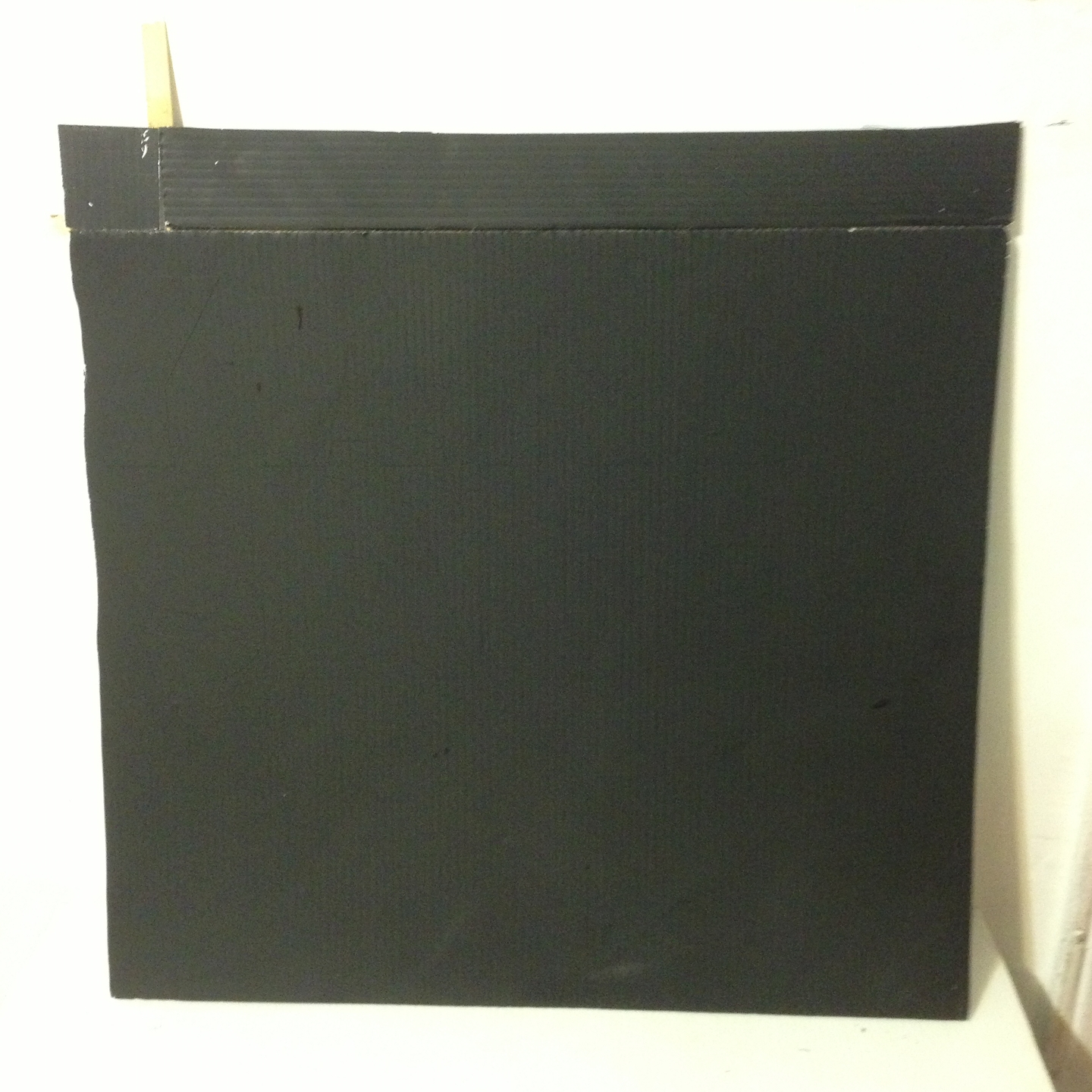
This isn’t pretty, and the paint may want a bit of a touch-up, but it should work.
(2013.0704, late evening)
Once again I am seeing behavior I do not really understand. I get a good solid pattern from the coherence test, but the fringes from the Michelson on the holography platform gain and lose contrast as I watch. There isn’t enough room on the platform for holography and an interferometer; I will probably have to steal a small amount of the beam and put it through a Michelson before it goes to the platform, so I will know when it is good enough to use. Although this is annoying, it is not likely to be particularly difficult. ...We hope.
(2013.0706, afternoon)
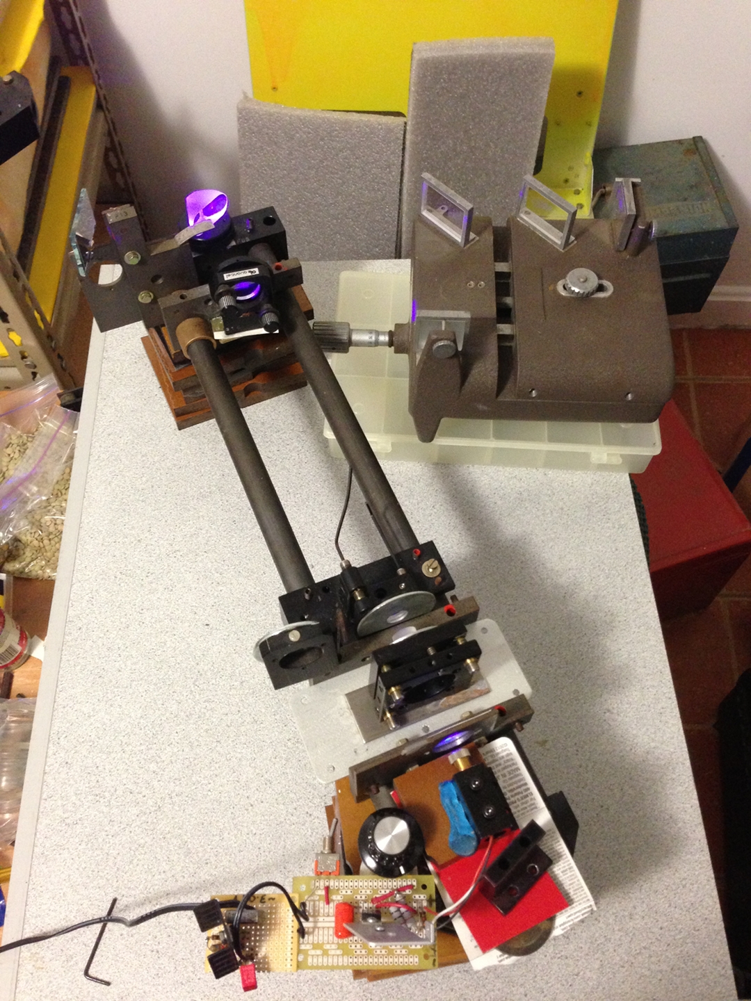
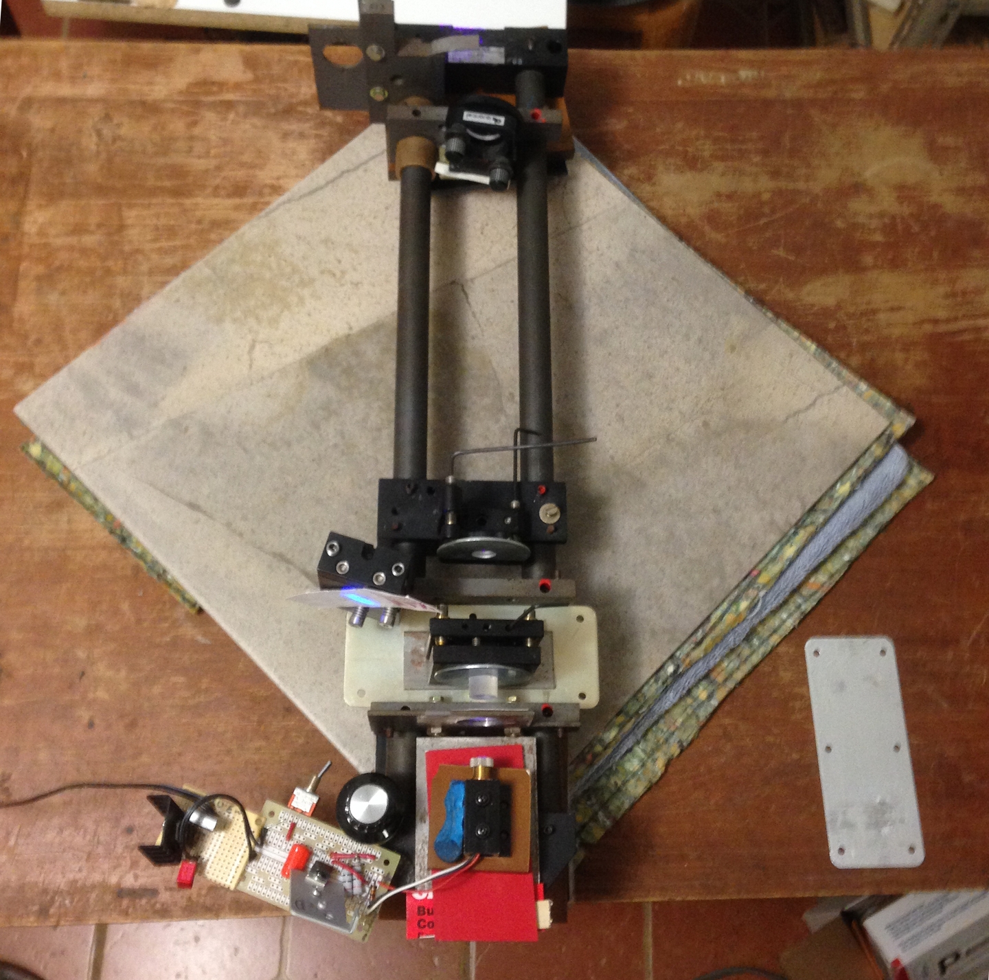
I put Dan Barlow’s Michelson on the table that the laser is on, and used a prism to divert a small amount of the beam into it. I also changed the display of the coherence test, so I can watch both patterns easily. Here is the current setup:
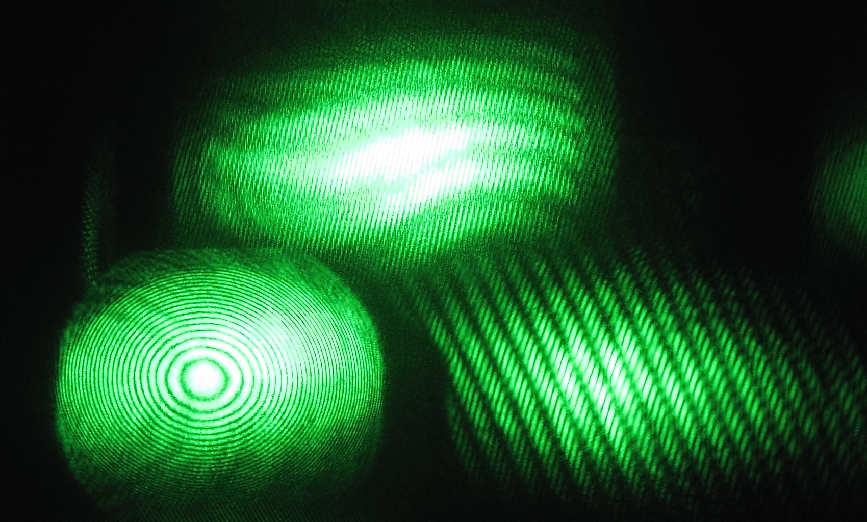
Here are a few of the patterns I’ve been seeing. First, one that looks reasonable to me:
[The coherence test pattern (on the right) has good contrast, and so does the pattern from the Michelson.]
The next one is expectable, though not as good:
[My conclusion from looking at this is that the coherence length is better than a centimeter or so (that’s the pathlength difference in the Michelson as it is currently set up), but significantly less than 25 cm. This means that although the Michelson gives reasonably good fringe contrast, the coherence test fails.]
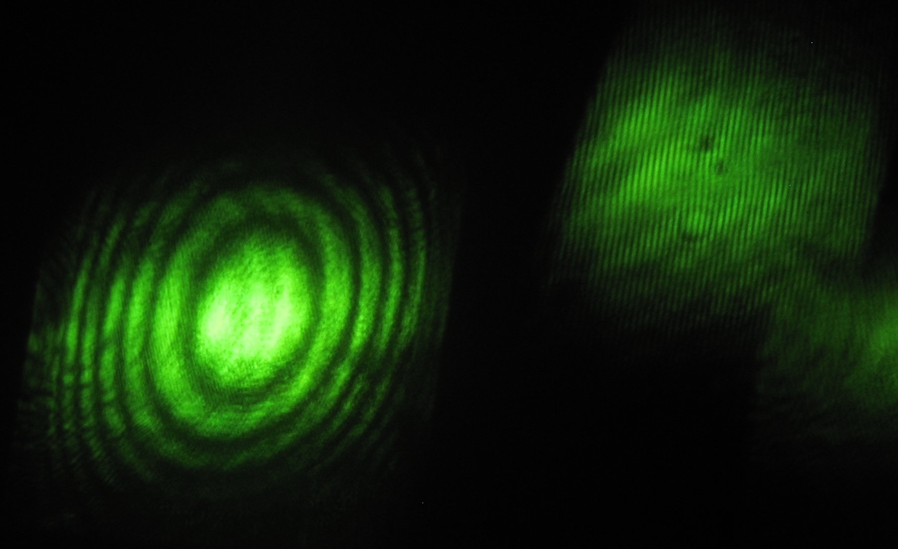
Here, however, are two examples of something that doesn’t make sense to me:
How can the Michelson fail to show good fringes when the pattern from the coherence check is easily visible?
ISTM that either I am misunderstanding the coherence check, or something very strange is going on here. I am probably going to have to look at these patterns with a photodetector and an oscilloscope, in case something is changing too rapidly to be visible by eye, though I can’t offhand imagine how that could result in what you see in this image.
(2013.0709)
Tommy Johnson points me to this page, where there are some interesting notes about the way coherent light behaves, which can be somewhat cyclical. It could be that the spacing of the 2-plate test puts it on or near one of the “coherence peaks” when the Michelson is somewhere in one of the valleys. That’s an interesting notion, though somewhat scary in that it would mean that the coherence length is shorter than I had thought. OTOH, logic suggests that if the coherence length is well under 1 cm, then the 2-plate test would have to be at a very large “peak number”, which is not likely to give much contrast; and if the coherence length is more than 1 cm the Michelson should be making nice crisp fringes, which it isn’t. Thus, this explanation seems to fail.
Either way, ISTM that making a hologram of a ruler would be relatively straightforward and a good way to improve my understanding, so I am beginning to assemble the shrouding that will go around the holo platform to exclude air currents and stray light. It is crude, but this work is primarily intended as a proof of principle before I go off to another project that I want to pursue, and it should be “close enough for folk music,” as the saying goes. (Alternative, possibly dating from the World War II era: “close enough for Government work.”)
(2013.0711)
I should note that unless I design the setup very carefully, the ruler will not be a precisely scaled indication of the coherence length of the laser; it is intended more as a general indication of what’s going on, so I can better understand the behaviors that I’m seeing.
(2013.0719, evening)
I have been reading parts of Frank J. Duarte’s Tunable Lasers Handbook, and I found a mention of an excimer laser that is tuned with three [carefully synchronized] tilted etalons. That sounded reasonably interesting, so I read up on tilted etalons on the Web, including the article at Dr. Rüdiger Paschotta’s excellent site. This continued to sound both interesting and potentially viable, and I decided to insert a second etalon between the laser and the existing etalon, to see what might happen. After a bit of fussing and fretting I seem to be getting tighter tuning, with extremely sharp fringe contrast, but typically harder to achieve, and with shorter periods of stability. Here is a look at the current setup (except that I have replaced the support under the Michelson since I took this photo), along with fringes from the Michelson [left] and the 2-plate coherence test [right].
I have also changed the anti-vibration stack of the holography platform, and I put the other Michelson back in place on it to see how stable it is. I am still not enthralled, but I think it may be very slightly better than it was. (More about this later.)
(2013.0807)
Dan Barlow suggested that I use a meter movement as the shutter. He even provided a few, so that if I messed one up I’d have a spare. I was wondering what to use for the “flag” that would obscure the beam with the shutter closed, and he suggested that the little anti-theft tags you find in occasional books and other objects contain nice thin steel sheets, some of which are easily removed. They are thin enough to be quite lightweight, but sufficiently stiff to serve nicely. Dan was kind enough to provide a tag, and also to laser-cut windows in the front and back plates of one of the meter movements. It turns out that although one of the sheets gets mangled when you disassemble the tag, there are two others in a separate compartment, and if you are careful you can get them out intact. I cut one into two pieces and used CA to attach them to the needle of the movement. I promptly found that I also needed a counterweight, for which I used part of a hand that I had removed from an alarm clock while I was making a timer for a mist-tunnel, which is an entirely different story, and two little pieces of heavy copper wire. Here’s a photo:
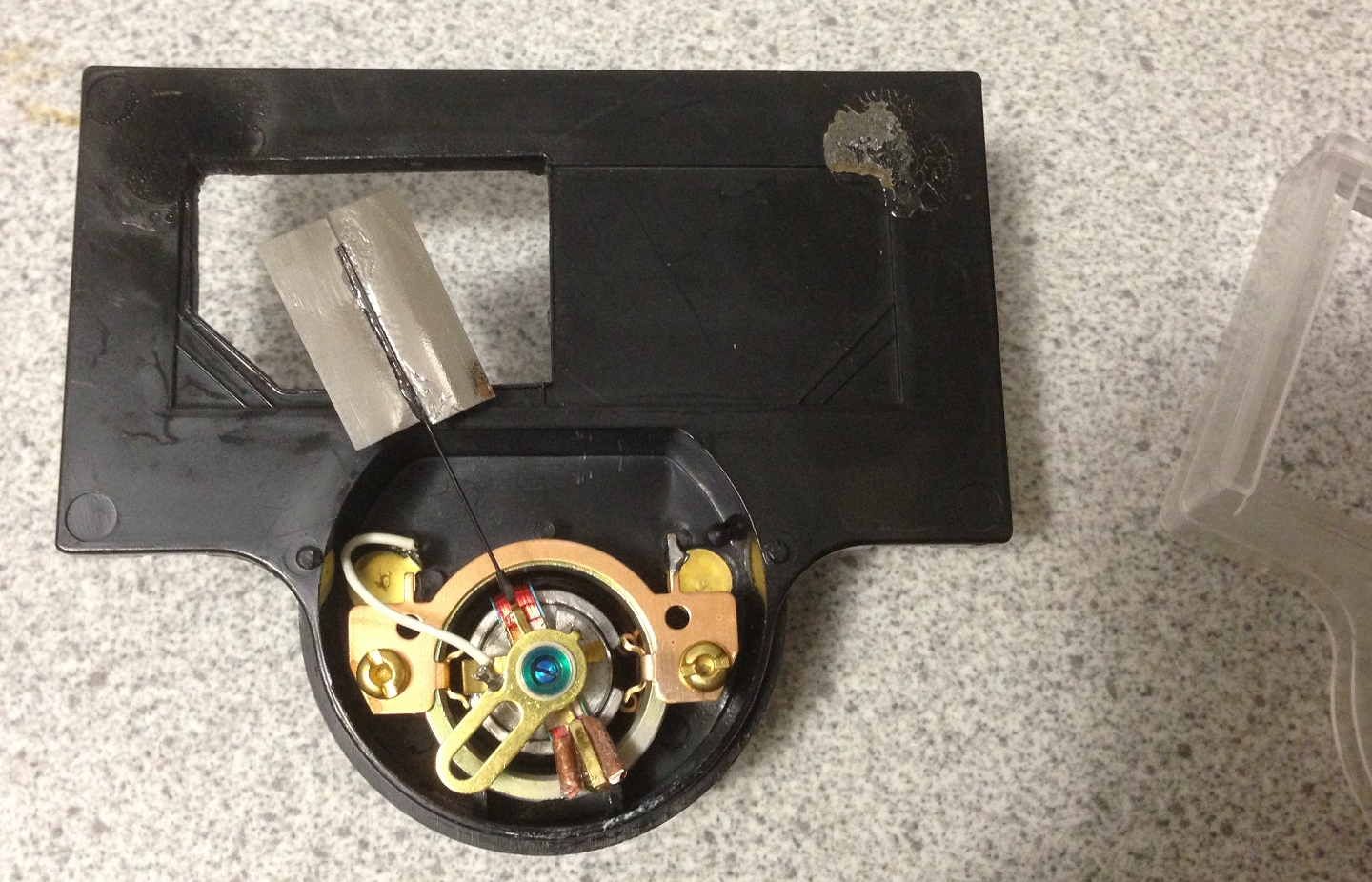
(You can see part of the front plate at the right edge.)
The movement appears to be 50 or 100 μA full scale; I expect to drive it with a timer built around a 555 chip (long may it wave!). Here is the circuitboard in its original incarnation, not even tested yet because I only just finished it a few minutes ago:
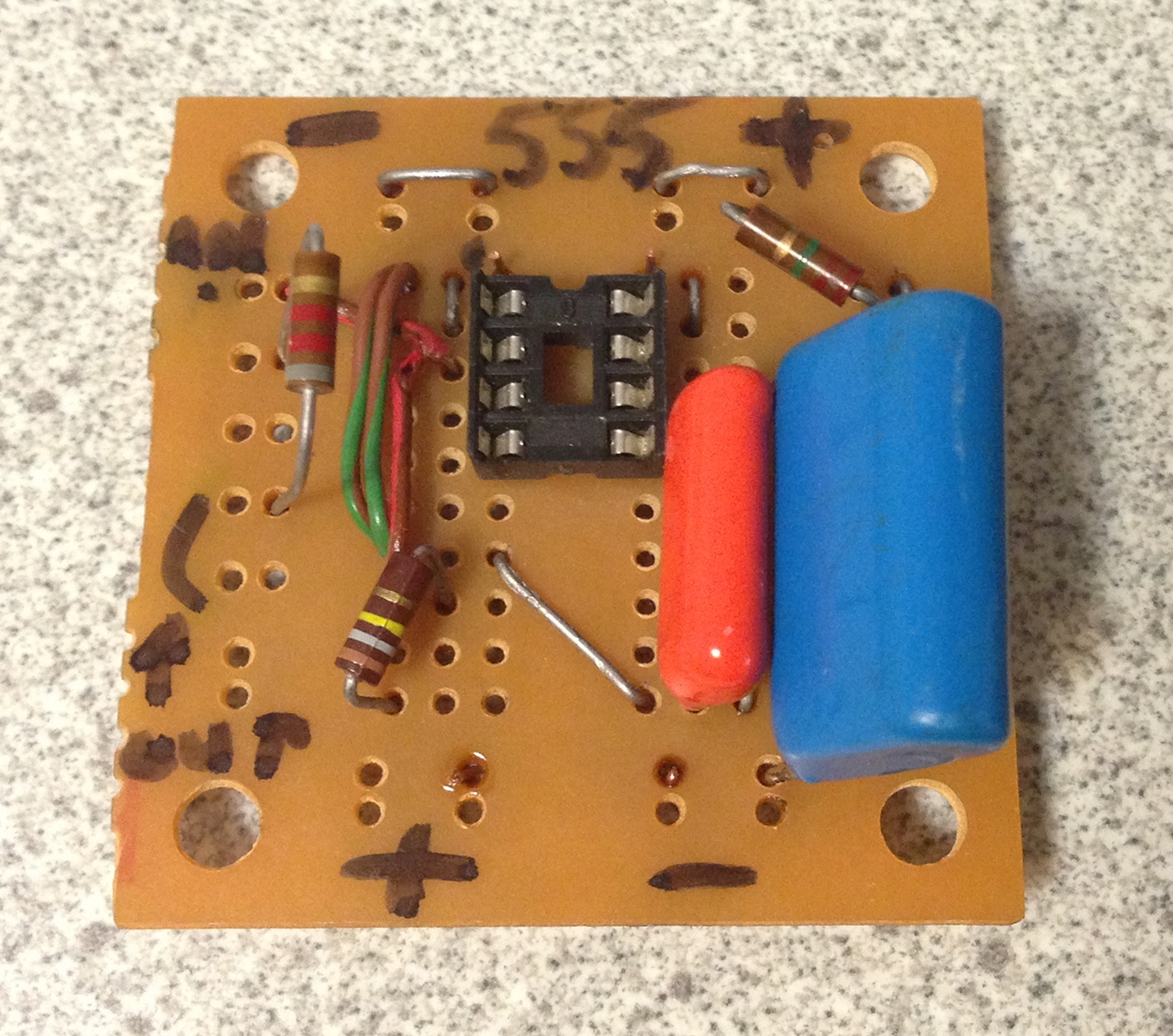
I have, for the moment, used a 2.2M resistor with a 1μf capacitor (the large blue object in the photo), so the shutter should open for about 2.2 seconds. Eventually I will probably put this circuit into a box with a switch or an adjustable resistor, so I can choose appropriate exposure timings. Because I expect to use a 9V battery (or equivalent wall-blob) to power the circuit, I have included an 8.2K series resistor to limit the current through the meter movement. It may not be large enough, but it is easy enough to replace. (See below.)
(later, that same day)
I had missed one of the pullup resistors, which I found and added when I ohmed out the circuit before testing it. It came up working, which was quite gratifying: even simple electronics has a tendency to require tweaking before it will run properly. I then played with the series resistance for the output until the shutter movement worked well; with a 9V battery as the power source, it seems to want 10K. One step closer to the goal...
Here’s a quick drawing of the circuit:
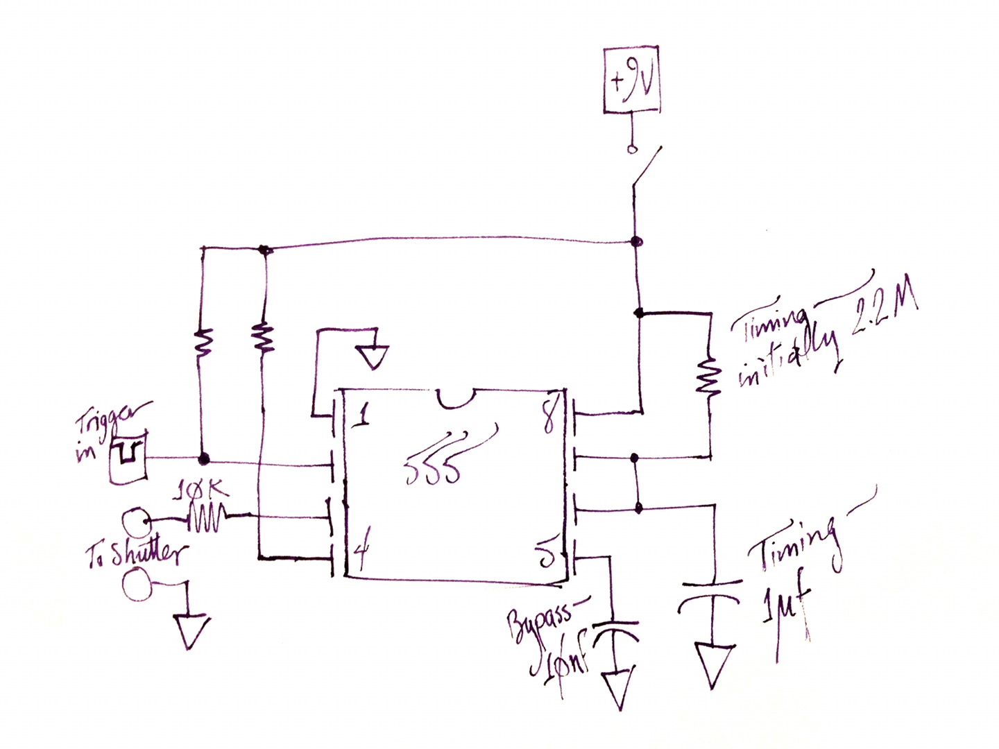
Notes:
Meanwhile, I am finding that I get good stability from the laser with the new etalon just a little bit off angle. (This is not actually surprising.) At some point I may provide a photo or two, though they are rather boring. Suffice it to say that the fringe contrast is crisp, and stays that way for a whole lot longer than I expect to need. I think I’m occasionally seeing stable operation for several minutes at a time now, which almost suggests the possibility of making Denisyuk-type holograms if I can figure out a recording system that doesn’t involve Cr VI — I have no desire to expose myself to that stuff, thankew. (A few people have succeeded in using iron-based chemistry, which is encouraging.)
(30 August, 2013)
I begin to suspect that there are other potentially viable systems, and I will be exploring at least one of them if and when I have time. Meanwhile, it appears that Ferric Ammonium Oxalate absorbs a lot better at 405 nm than Ferric Ammonium Citrate does. I am wondering about using dyes to sensitize the material, but that’s probably very tweaky.
Also meanwhile, I have revised the stack yet again, to see whether it makes much difference. This is preliminary; it is slanted, and I will be attempting to level it...
You can see parts of the Michelson on the top. Unfortunately the pattern (on a paper viewing screen, near top center in the photo) is too bright to see clearly.
(01 September, 2013, evening)
The Sorbothane pieces are rather soft, and I’ve been thinking about that. It occurred to me that some sort of glop (as it were), loaded with something appropriate, might help damp out vibrations. Accordingly, I started looking around. This afternoon, the Range Safety Officer directed my attention to some hair gel at the drugstore, and that seemed extremely promising. I think this jar cost me about $2.39...

As an initial test, I loaded it by mixing it with about an equal volume of rolled oats. I didn’t have enough oats to make as much as I wanted, but there are now three plastic bags of the mixture under the top plate of the holography setup. (In the photo above, the top two plates are touching each other. That’s where the bags of glop currently reside.)
I also moved the uncoated etalon a cm or two further away from the laser (and refocused the collimating lens), and I think I’m finding it slightly easier to get decent locking...
(2k13.0906)
I have also put an iris in the path of the beam, to get rid of some of the noise that surrounds the central region. In the next photo, the pattern at the top is from the Michelson on the holography platform, the middle pattern is from the Michelson on the laser platform, and the bottom pattern is from the two-plate coherence test. The top pattern was originally so bright that it made the others difficult to see; I have tweaked the brightness and contrast to even them up a bit.
This set of patterns can remain stable for well over a minute.
(2013.0917, early AM)
Here is an overview of the current setup, with a ruler on the coherence test so you can see that the two plates are about 30 cm apart:
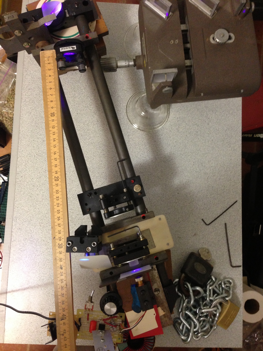
(The locks and chains at lower right are a balance weight; the laser is on a stack of stuff that is intended to cut down slightly on vibration, and it is a bit tippy. This stack isn’t as good as the stack under the holography platform, but it doesn’t need to be.)
(2013.1014)
It turns out that focusing even a few hundred mW of violet light onto an older coated etalon and leaving it that way for a long time is suboptimal and deprecated. Here is a photo of the etalon, showing the bright spot where the damage has occurred, followed by a photo of the pattern from the Michelson on the holography table, showing a very peculiar appearance, almost as if the light were shining through leaded glass...
...I have moved the beam a bit, and I inserted a beam stop
between the two etalons.
(2013.1125, afternoon)
After a gap for a conference and some time spent on other pursuits involving the cultivation of Camellia sinensis, I have returned to this project. My first actions were to replace both of the supports for the platforms. I found a nice little oak table being thrown away, presumably because it originally had a glass top (17.5" x 25.5") that got broken; I replaced the missing top with a piece of heavy plywood, and moved the table to the basement. Because of space limitations I positioned it with its long axis parallel to the wall, and was obliged to drop a piece of glass across the antivibration stack so I could position the Michelson on it. I put pieces of chipboard on the glass to protect it.

Then I swapped out the table that the laser assembly sits on, because it was far too wobbly. Again, I was obliged to orient this table parallel to the wall (more or less), and the available supports were a bit small, so I rotated one of them to put the diagonal under the laser setup. With the addition of some antivibration mounting, which may be visible in the photo, the result was just about long enough.
As before, if I tweak the etalons to be a bit off-angle with respect to the beam I can get a reasonable pattern from the Michelson for some seconds at a time. The pathlength difference is about 7 or 8 cm at the moment, but it was more like 10 or 12 cm when I first did the setup, and the results were about the same:

(The bullseye pattern has lots of rings because of the relatively large pathlength difference. [If you are ever obliged to get white light fringes from a Michelson, you may be able to use this fact to get to a good starting point: maximize the central region and minimize the number of rings around it.] The peculiar shape of the pattern is largely caused by the fact that the camera was aimed into the viewing screen at an angle.)
I expect to make the initial test setup shallow, so that even if the coherence length during a period of locking is less than, say, 10 cm I will still get at least something on the plate. We hope.
(2013.1205)
Here’s an image from yesterday:
This one shows 3 patterns; at the top is the output of Dan Barlow’s Michelson, which is on the same table as the laser. The fine vertical stripes result from the fact that I used an ordinary coated window as a beamsplitter to send some light to this device; they are more or less ignorable. The wavy horizontal stripes are the pattern from the interferometer itself.
At bottom left is the output of a Michelson on the holography table, as before. It is a tight bullseye because the pathlength difference is substantial, probably on the order of 10 or 12 cm. (If/when I measure it, I'll provide a more accurate value.)
At bottom right is the output of the two-plate interferometer. Milan is uncertain about how well this scheme actually works, and I wonder whether interpreting it may be somewhat complex. Are the two patterns merely overlapped, or are they actually interfering with each other? If the former, the result indicates coherence length greater than the thickness of each plate on its own, but less than the distance between them. If the latter, then presumably the result indicates coherence length at least as great as the distance between the plates. (On occasion, I&rsqo;ve seen one of these patterns fall apart to the point at which only one set of fringes was visible, which indicates coherence length greater than the thickness of the thinner plate, but only just.)
I have been tweaking various settings, in an attempt to find some sort of sweet spot where the setup will achieve lock as displayed in all three patterns, and will maintain the lock for at least 10 or 15 seconds, significantly longer if possible.
(2K14.0126, late evening)
On the 21st, I acquired the following object at a thrift store in Laurel, Maryland:
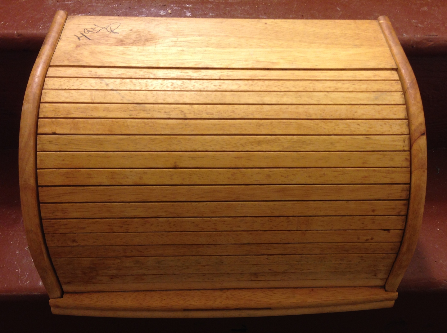
I’m reasonably certain that to any ordinary person this appears to be a smallish breadbox; but to me it looks like a nice little enclosure for holography. I have cleaned it, and I intend to spraypaint the interior flat black. I will have to make a hole in one of the sides, to let the beam enter. I have not yet decided where to put the hole, but I am leaning toward the front of the right side. (It depends on various things, such as how high up the beam is when it reaches the holography table, though that’s somewhat fungible.)
More as it happens...
More, specifically about the requirements that must be
met in order for holography to be successful, on
the next page of this set...
To the Main index for my research
Contact:
You can send email to myfirstname [only 3 characters; no “H”!] at the same domain you see in the URL of this page.
Last modified: Sat Jan 24 12:04:49 EST 2015