[Work begun in January or early February of 2013]
NOTE, added on 24 Feb, 2015: If you are not here to see all of the contortions I had to go through, you can skip to the page where I begin to see actual results.
If you want to use a diode laser to make holograms, you will find that it is eminently feasible. I’m fairly sure that people have been doing it since at least 1997, and some of them have been getting very nice results since at least 1999. One issue I regard as a problem, though, is that they have classically used low-power red (and more recently green) lasers that require sensitized media and relatively long exposures. If you can find a [green] DPSSL with good coherence length and relatively high output power you can use a shorter exposure, but you will still require sensitized films and/or plates.
My thought for this project is to try using a violet diode, which should not require any sensitization. The trick is to see whether I can achieve reasonable coherence length at relatively high power. (This probably ends up being several amusing projects, even if the original objective proves to be difficult or impossible.) I am hoping that aside from possibly stabilizing the temperature of the laser I can use an entirely passive scheme, and that’s what I have been working on as I start the project. If I can’t manage with a purely passive optical setup, I will start thinking about active stabilization.
Various articles state that the native linewidth of a red diode laser is about 20 MHz. That’s more than narrow enough for a modest hologram, and I don’t need to tune the laser, so I can probably get away with a simpler setup than the ones I’m finding in these articles. All I need, really, is to get the laser to run on a single line while delivering reasonable power.
There are many papers on the Web that deal with the issues involved, typically from a spectroscopic standpoint, but I have not yet found one that even mentions violet diodes. Moreover, the linewidth and stability requirements for most spectroscopic applications are far more stringent than what I expect to need for small holograms, particularly for AgX emulsions. (I do not want to deal with Cr VI, so if I want to use a nonsilver medium I will have to work up something other than DCG. I may discuss that issue in a later posting.)
To start this project I went up on eBay and bought a [claimed] 700mW [claimed] single mode diode. It does appear to put out a single spot, at least when I run it at about 300 mW. Frankly, as of mid-September, 2013 I haven’t been able to find any data on the Web to support the existence of single mode violet diodes that are rated to put out more than that, so I have some doubts about the claimed output power capability.
I should note that the term “single mode” in the diode description refers to the transverse mode structure. That’s entirely different from the longitudinal mode structure. A single-mode laser diode can operate on lots of longitudinal modes, and when it does that it has very poor coherence. OTOH, a diode that puts out more than one transverse mode probably cannot be locked to a single longitudinal mode (short of truly advanced magic that causes the different sections to become strongly correlated, which I suppose is possible in principle but is not at all easy in practice), and thus is not a good candidate for this application.
So far, I have tried two major stabilization methods. Milan Karakas mentioned one that I think is very interesting: you put a focusing lens into the beam, and you place a flat surface at the beam waist. (A glass plate is typical; I tried both glass and sapphire.) This plate is aligned to reflect back into the diode, and thus it establishes a larger cavity, which has different longitudinal modes from the native ones of the laser diode. If you get it adjusted correctly, if the plate is reasonably flat and clean where the beam is hitting it, and if the diode is one that works well this way, you can get a significant improvement in coherence length. Sometimes. Depending.
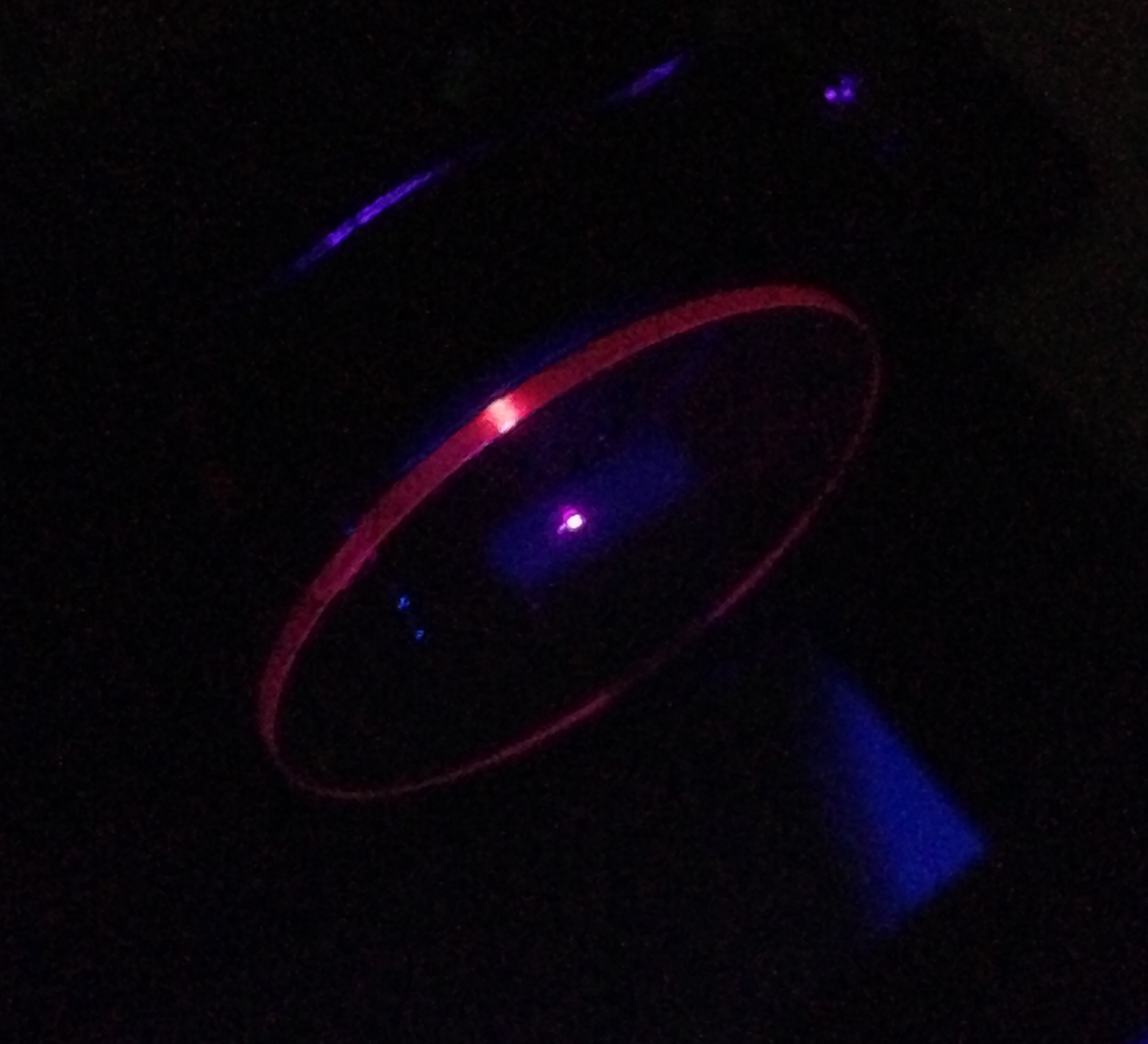
Using this method with the 700mW diode, driven by a current regulator that I made from an LM-317T, and limited to a maximum of about 260 or 270 mW, I got results that were rather confusing, but intriguing. When I tried a sapphire sewer-camera window as the stabilizer plate I even got a small surprise:
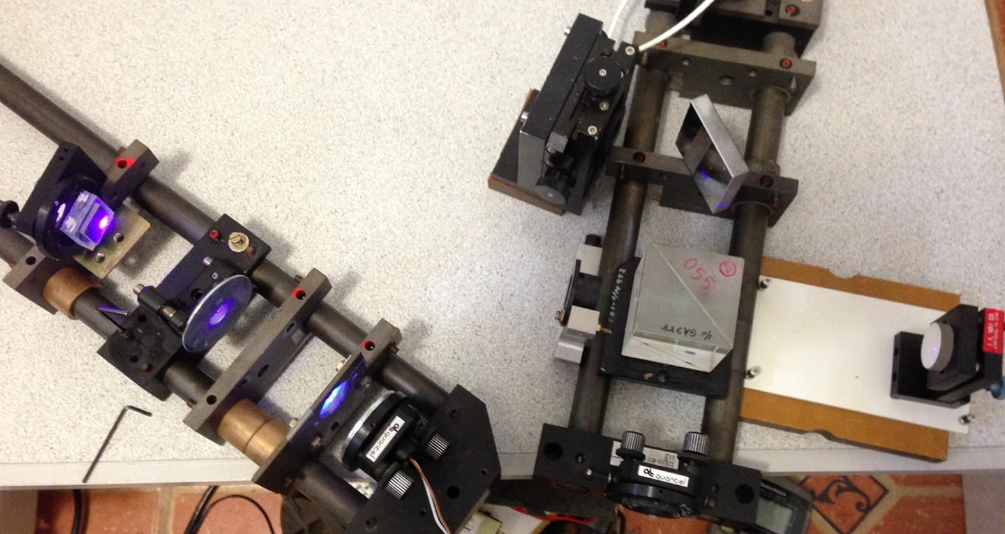
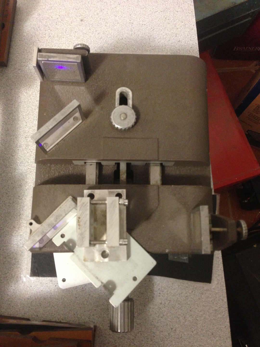
I eventually removed the plate and the focusing lens, and substituted an etalon. I continued to get confusing (but interesting) results, and eventually I swapped out the big laser and substituted the smaller one. After a false start in which I accidentally equalized the pathlengths (if you get very stable fringes even when you first turn the laser on in a cold start, you are entitled to be suspicious), I eventually started to get results that substantially match what you might expect. Here’s an overview of the setup;
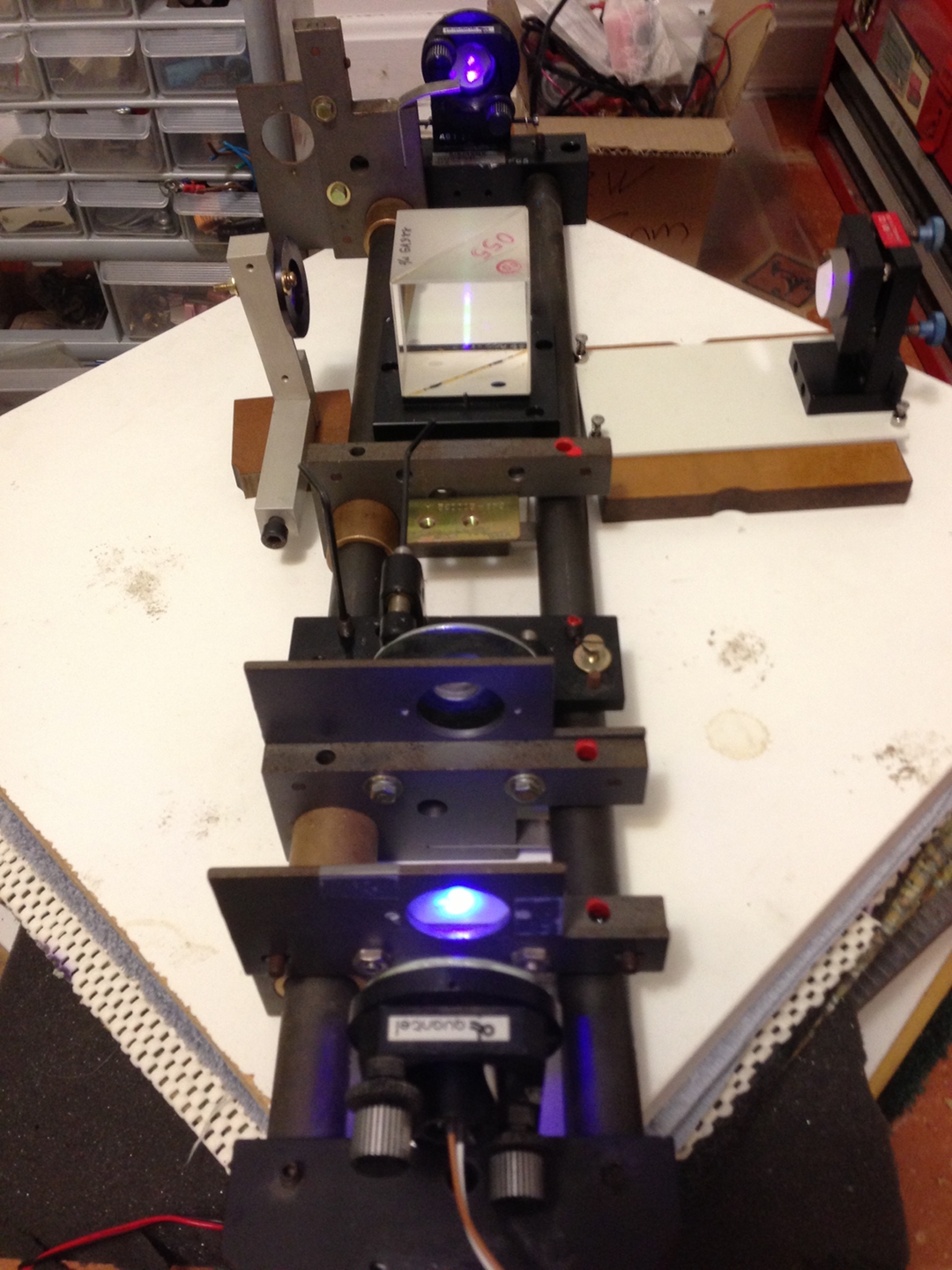
The laser (in the mount at the bottom of the image) is shining through a hole in a piece of paper. This lets me align some of the other components.
When I first saw the fluorescence of the beamsplitter I was concerned, but it doesn’t seem to be taking too much power from the beam, and it facilitates alignment.
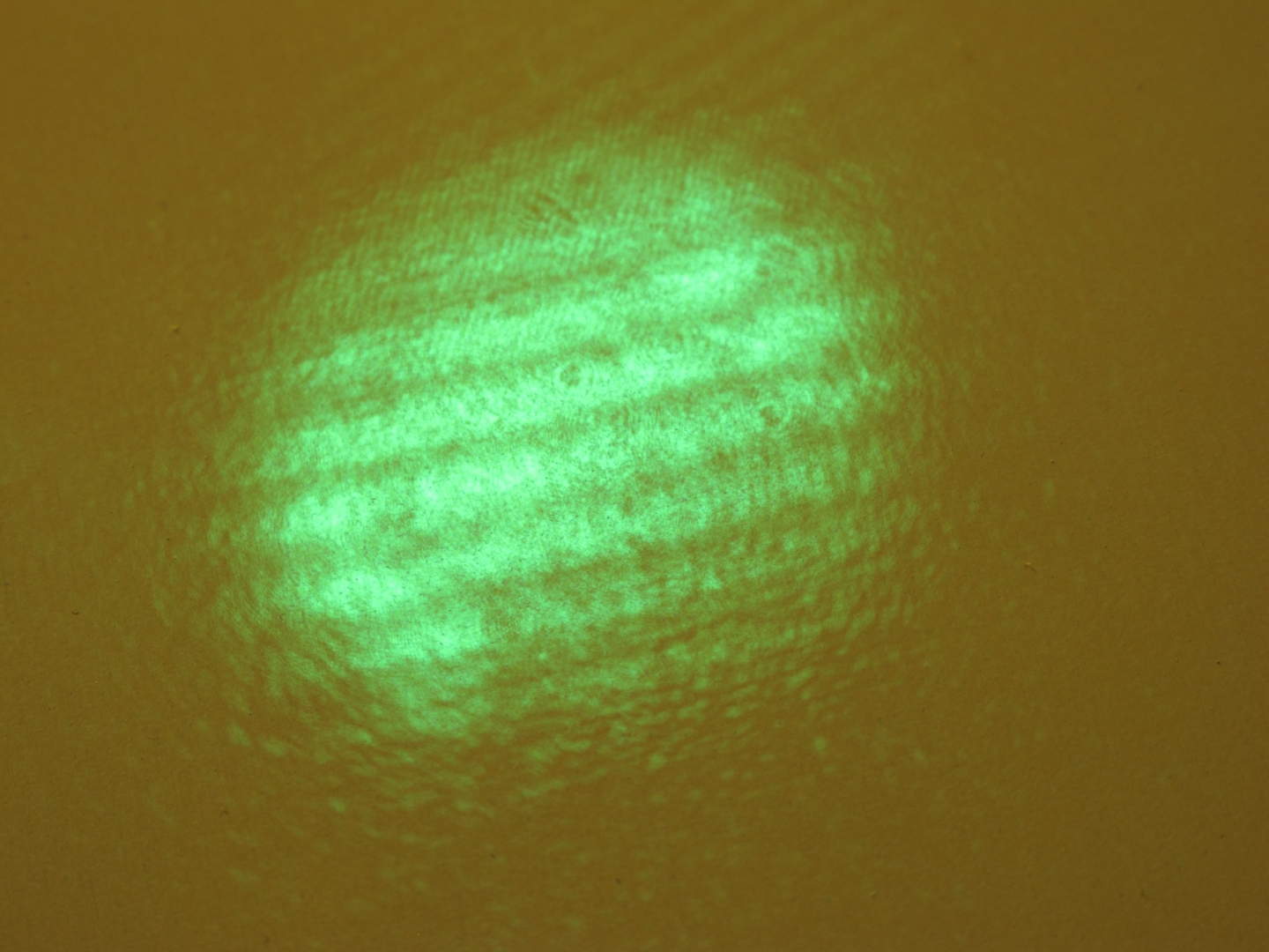
Here are photos of the pattern, first when the laser is not locked to the etalon, and then with at least a partial lock. Because the pathlength difference was about 4 cm when I took these, the fringes indicate coherence length of that general scale.
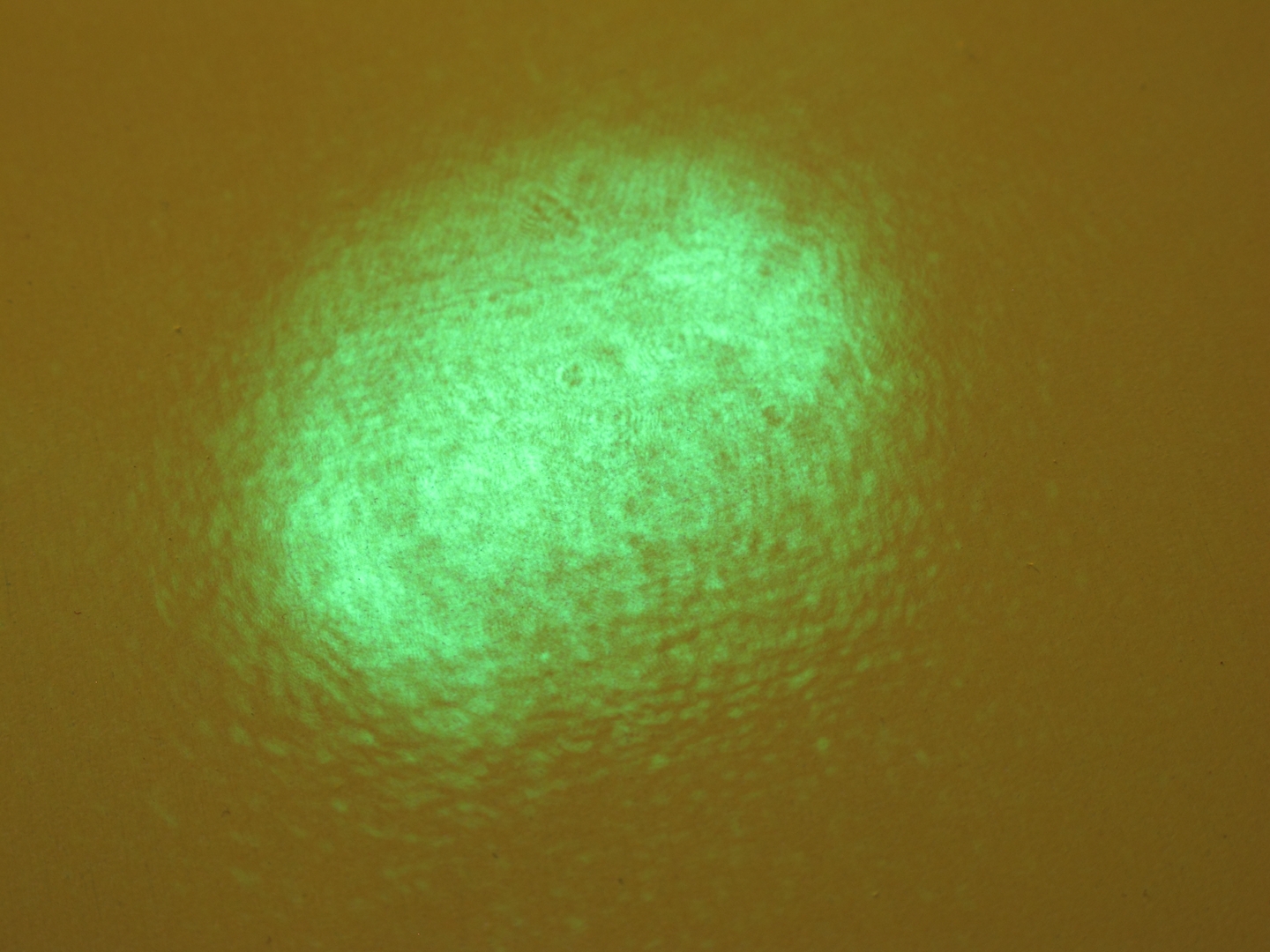
(I have since increased the difference to about 6 cm, with very little change in the behavior of the pattern, though it looks somewhat different because I also changed the focus of the collimating lens on the laser.)
(Evening of Feb. 28, 2013)
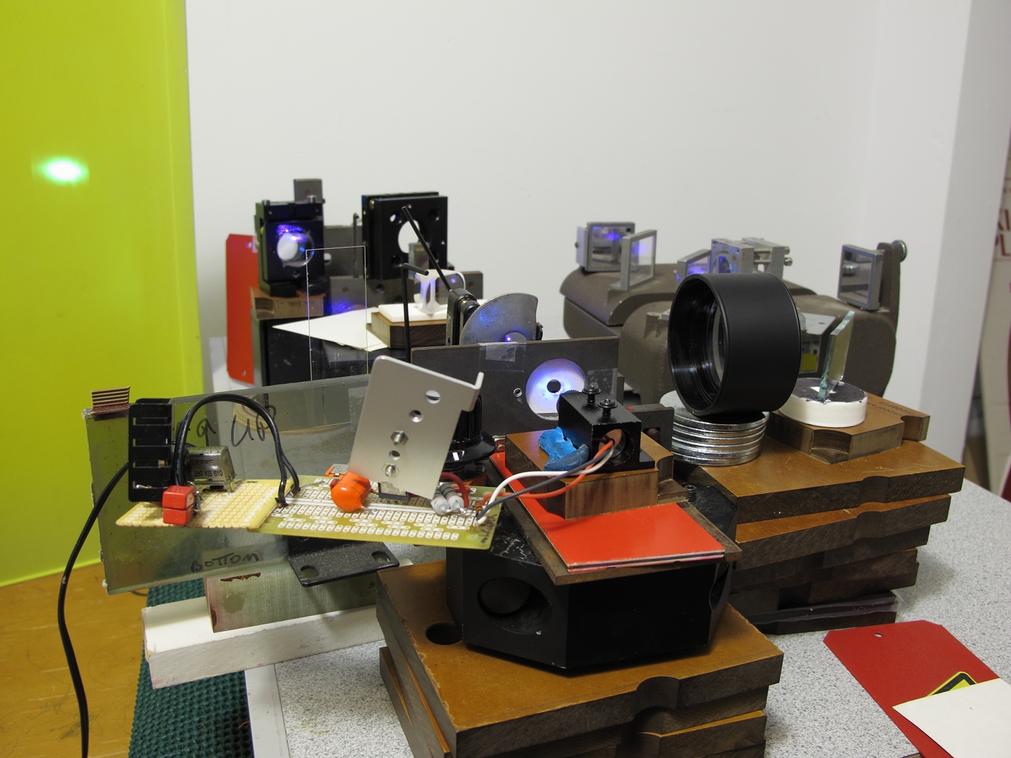
I have changed the setup to include a grating. It now looks about like this:
[The laser is at the bottom, slightly to the left of center; in terms of the image, it is pointing to the left and up. The beam goes through a hole in a paper screen, which facilitates alignment, then through the etalon (attached to a large steel washer that is attached to a mirror mount), and then to the grating, which is near the left edge of the photo. From there it goes to a focusing lens (just below and to the right of center, barely to the left of the beamsplitter cube), then through the beamsplitter, and from there to the two mirrors of the Michelson interferometer (bottom, a little to the right of center; right edge). From the mirrors it returns to the beamsplitter, and goes to a steering mirror (silvery block, upper right, standing on one of the crossbars), through another lens to magnify the image, which is otherwise too small, and off to the viewing screen, which is out of the picture to the left.]
Here is a brief video that I took with my phone (forgive the wobbliness; it was handheld), showing the laser acquiring (and losing) lock, mode-hopping, and so on. The fringe contrast is quite decent from about 18 to 22 seconds.
It is very difficult to adjust all of the settings, and
I am just starting to learn how to do that. Most of the
time, the setup is out of lock, and I don’t have
fine enough controls on any of the mounts.
(30 March, 2013, ff)
I have been through various contortions since I wrote the material above, with lots of [probably pointless] photographs and videos. I am using the high-power diode again, and I have put another LM317T in as a voltage regulator upstream from the current source, to decrease the noise. (Thanks to Todd Johnson, of FNAL, who saw mention of this technique on the Web, and told me about it.)
It is exceedingly difficult to understand the behaviors of the setup, and I spent quite a bit of time varying the settings and trying to figure out what was going on with it. I changed out the collimating lens on the laser for a “405-G-2” single-element glass one; changed back and forth between an etalon with coated faces and one with uncoated faces; changed out the grating for a cleaner one; changed the order from the grating that I was using for feedback to the laser; and eventually decided to try a prism and a mirror instead of a grating. The prism provides far less selectivity, but it has lower loss, and I am hoping that the selectivity will not be a problem.
One thing I noticed is that I don’t seem to get the fringes to lock if I align the etalon as precisely along the beam as I can. I think there are exceptions, as for example when I happen to achieve the condition that Milan uses (mentioned above), but not many. For the most part, I have to walk the etalon a wee bit out of alignment, and there is a limited angular range over which I seem to get reasonable fringe lock. Unfortunately, even in the best case I rarely get locking that lasts longer than a second or two. This is quite frustrating. (...But see below for continuing results.)
I am working with a friend on an image-analysis notion that could eventually let us predict a good time to make an exposure, but that involves computing and complexity that I would like to avoid if I can. OTOH, it’s certainly an interesting project, and it will have other uses.
When I get a chance I will take a photo of the
prism/mirror setup [see below]. In the meanwhile, I will
note the fact that I am taking a reflection from one of
the prism faces as the input to the Michelson, so I
don’t lose any power that I wouldn’t be
losing anyway. The mirror I’m using reflects only
a little at 405-410 nm. This means that I get a single
output beam, which goes through it. I hope that will be
convenient if/when I get around to building a holography
table.
(2013.0405)
The setup is very messy now, but it looks more or less like this:
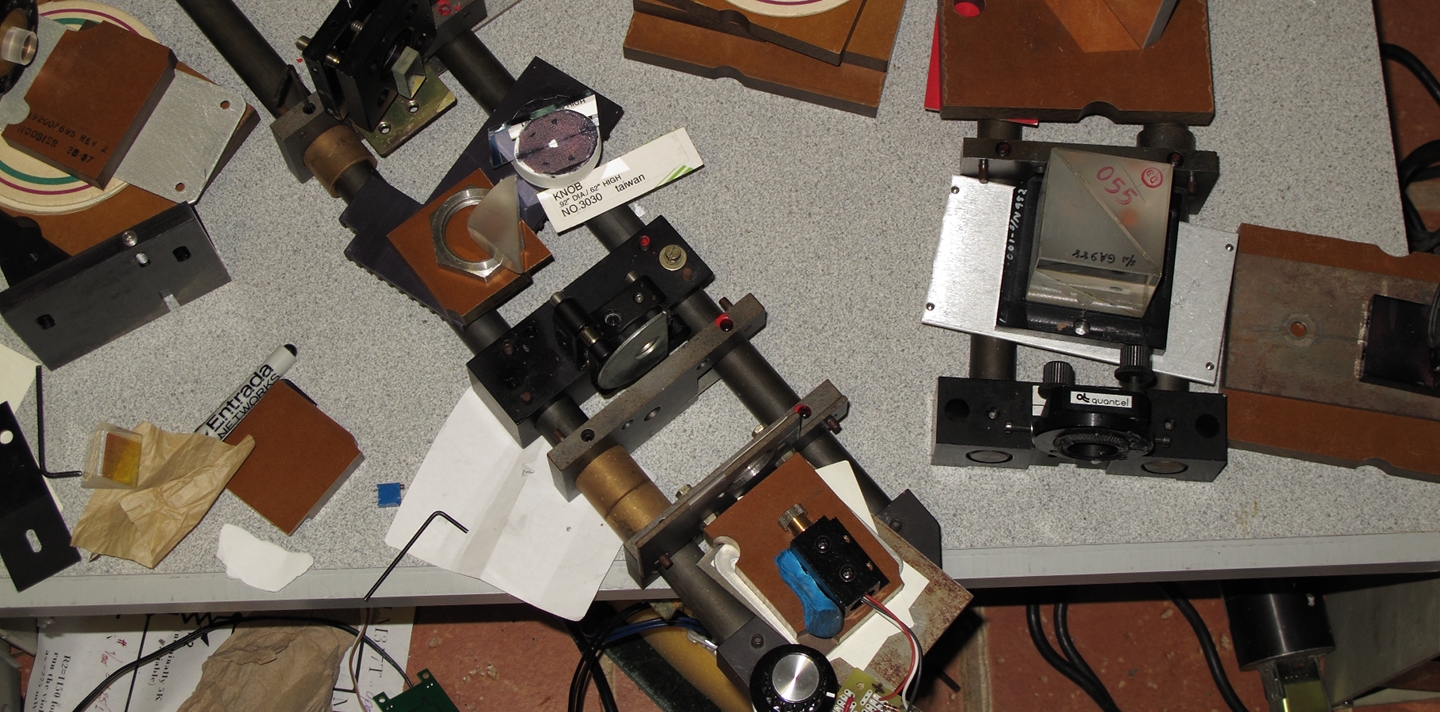
The laser is near the bottom of the photo, a little to the right of center. (The adjustment knob for the current source that drives it is just at the bottom of the photo, directly below the line of blue tacky stuff that holds the laser’s housing to a piece of brown phenolic board.) The beam goes up and to the left, through an aperture, continues through the etalon (held in a black mount), passes through the prism (sitting on another piece of brown phenolic), and continues up and to the left to a flat output coupler intended for a UV helium-cadmium laser (95 or 98% reflective at 325 nm), which is at the top left corner of the photo.
Meanwhile, the first bounce from the prism goes to the relay mirror that is just above it in the photo, and from there to the large beamsplitter cube on the right. You can see one of the mirrors of the Michelson interferometer just below the beamsplitter. The other is off to the right, outside the photo, but you can see part of its mount. The difference in path lengths is probably on the order of 10 cm.
Here (photo, below) is a view of the aperture, with the return beam from the HeCd output coupler visible on it. The OC is wedged, so it provides multiple reflections in a wide range of brightnesses, three of which are visible in the photo. I am using the second bounce for feedback, and as you can tell from the photo it is not aligned precisely with the beam coming out of the laser. I’m pretty sure that the etalon is also slightly misaligned, and my suspicion is that this is extremely important; as I mention above, I tend not to get fringe locking if the optics are aligned precisely to the beam. It is likely that even relatively modest reflections provide enough feedback to encourage lasing on multiple longitudinal modes. In fact, I am somewhat surprised to see fringe locking in this setup; with some diode lasers, destabilization has apparently been observed with as little as 1/106 of the beam returning to the laser. I will note that I have not seen locking when I used the brightest return from the OC, but the second bounce is still considerably more than a millionth of the output from the laser. I guess the combination of the etalon and the prism/mirror provides enough selectivity, if only just barely. (With earlier setups I have gotten brief periods of considerably sharper fringe contrast than you will see in the video that I link to below.)
If I block the beam to the prism, it is much easier to see other returns on the aperture; I keep the beams from the Michelson displaced off center so the laser doesn’t try to lock to them, though in fact that might not be a problem.
On various occasions I have tried blocking the beam between the prism and the OC in order to find out whether both the etalon and the prism/OC combination were having effects. With previous setups I typically saw situations in which the lock could improve either way — when it was bad with the OC, it improved without it. When it was bad without the OC, it improved with it. With the current setup the situation seems to be different: the fringe pattern certainly changes, but the lock does not seem to be all that much better or worse either way. Perhaps this is because it is neither lousy nor great; I don’t really know.
Here is about 40 seconds of video. It is uncompressed, so the file is fairly large (about 43 MB).
One way or the other, I am extremely pleased with this level of stability. I had hoped that there might be a “sweet spot” of this sort, and I think other people have observed stable operation at certain combinations of temperature and diode current; but I don’t think it often occurs at such relatively high output power levels. As far as I am currently aware, there wasn’t any reason to believe that such a condition absolutely had to exist for this diode, or even for this type of diode.
[ Here is a really splendid page of current vs temperature stability graphs for an ECDL [Extended Cavity Diode Laser] configuration that uses a grating, tested with a number of different laser diodes.]
At this point, I should probably just relay the output
beam across the room and build a holography setup to use
it. That will, however, have to wait until I have time
and cycles to deal. I just hope I can refrain from
messing things up before that happens — it is much
easier to tweak the mirror position or the etalon angle
than it is to build an entire holography table; and I
don’t know whether I could ever get back to this
level of stability, as I reached it entirely by accident.
(2013.0510, early AM)
After various fussing and fuming and fretting, punctuated by long periods of doing other things, I seem to have gotten the setup to a point at which it is moderately stable. I have eliminated the mirror, and I’m using the prism just as a beamsplitter, to send some light off to the interferometer. I think that the laser is locking partly to the etalon and partly to the Michelson; under other circumstances that might be bad, but I have no real reason to remove the Michelson from the setup, as I need it in order to decide when to start an exposure, so it’s fine with me if the laser locks to it.
I’m not entirely sure the laser is running on only one longitudinal mode, but it certainly isn’t far off, and the pathlength difference is close to 20 cm at this point. Here is the setup...
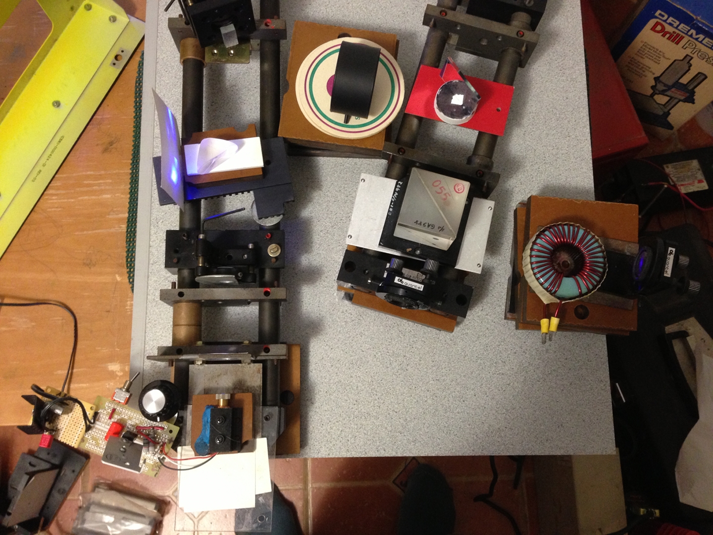
...and here is a video of the pattern from the Michelson, showing what looks like very reasonable stability for 30 seconds. (I took it with my phone, handheld, so it’s a bit wobbly.) There is some change, but I don’t think it’s enough to prevent me from making a hologram with an exposure of a second or less.
(2013.0518)
It looks like maybe 2 modes are running, so the fringe contrast is less than exquisite, but at least the pattern is more or less stable for several seconds at a time. I figured it was probably good enough to start making test holograms.
Then I took another look at the video at the bottom of this page, where he shows the pattern he gets if he shines the beam onto a microscope slide & lets it reflect back across the room. [This is a technique I learned from Milan, though Milan’s version uses two plates, and is more refined.]
So: I put the sapphire sewer-camera window (~1 mm thick; see photo, above) into the beam from the violet laser diode [after the stabilizer setup], and let it reflect onto a second fluorescent viewing screen. That should give me fringes when the coherence length is more than 1 mm, analogous to what’s on the ECDL page in the link above, only green instead of red, and with different fringe spacing.
I have seen fringes come and go, though usually not abruptly — I made a video in which it takes several seconds to go from nothing to fringes and from fringes to nothing. That seemed to be more or less typical. (I played around with the setup for a while, and got the fringes from the plate to be considerably more stable, so perhaps “several seconds” was partly caused by the laser not being fully warmed up. OTOH, in the ECDL video it seems to take about 0.5 to 1 second to show a mode-hop...)
Here’s the issue I'm having:
I can have little or nothing from the Michelson while the plate makes good crisp fringes, but that’s easy to understand: I need about 20 cm of coherence length in order to get good fringe contrast from the Michelson, but it only takes ~1 mm of coherence length to make fringes from the plate. So far, so good. (I have a video of this, but it’s pointless; just shows what you’d expect.)
What I don’t understand is how I can have crappy fringe contrast (or even no fringes at all) from the plate for an extended period while I’m seeing nice crisp fringes out of the Michelson, which happened quite a bit last night.
When the coherence length is ~20 cm, which it presumably has to be in order for the Michelson to give good fringe contrast, the fringes from a 1-mm plate have to be lovely... but sometimes they aren't. They come and go as if they had a mind of their own.
If this were mode-hopping, as in the ECDL video, the Michelson should also show it. I actually saw what looked like a mode-hop on the plate fringes at least twice last night, and it was very similar to what I see from the Michelson.
It is not possible for a laser to have 20 cm of coherence length at the same time it is having <0.1 cm of coherence length. That just doesn’t make sense. Therefore I am understanding this incorrectly, or drawing an incorrect inference somewhere.
This is driving me nuts.
(2013.0519, evening: things change for the better...)
Yesterday, Dan Barlow lent me a small Michelson interferometer. I have temporarily added a mirror mount so I can get grossly unequal pathlengths:
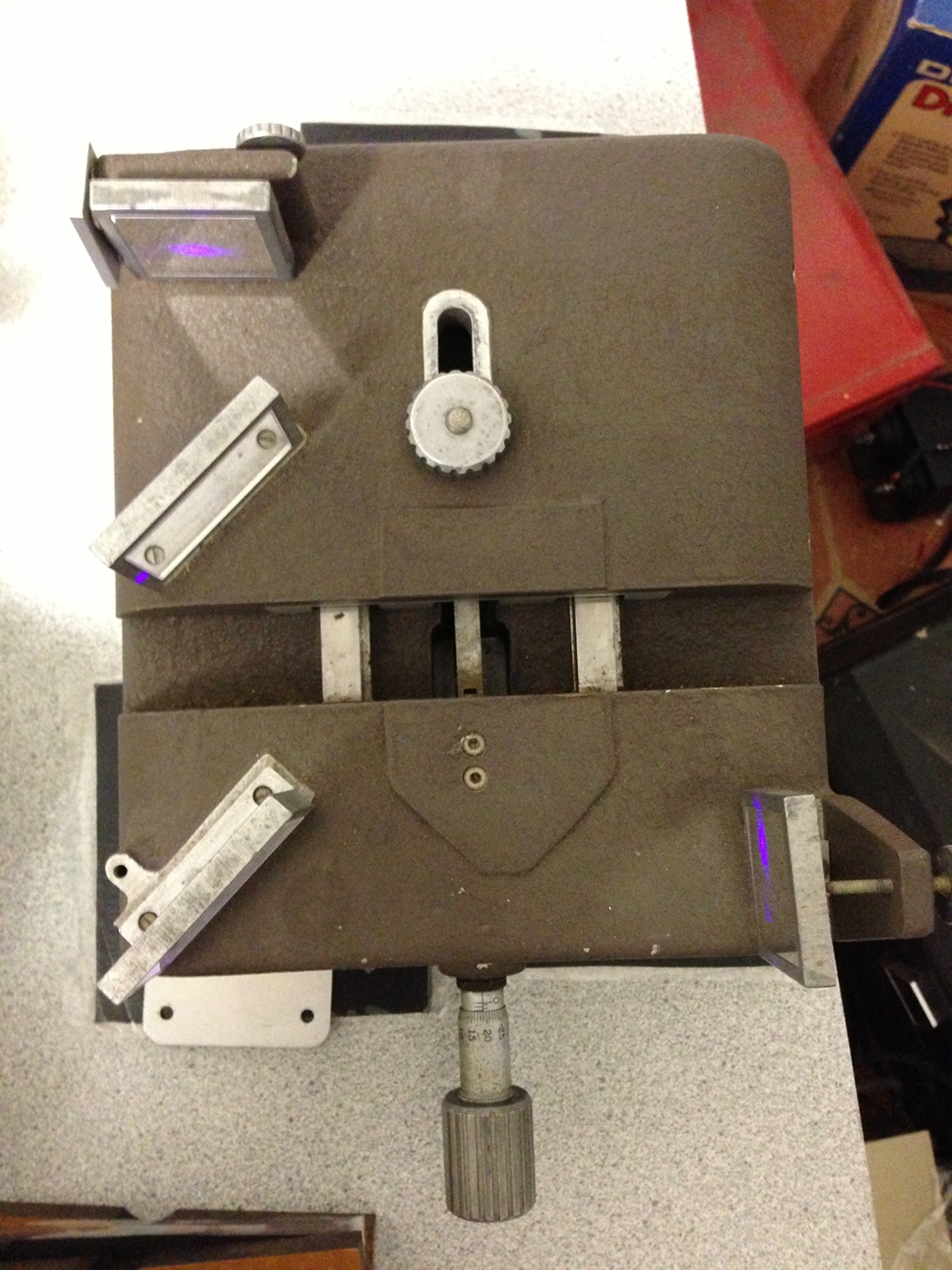
I replaced my original wobbly Michelson with this one, aligned it, and watched the patterns. First, a look at the setup:
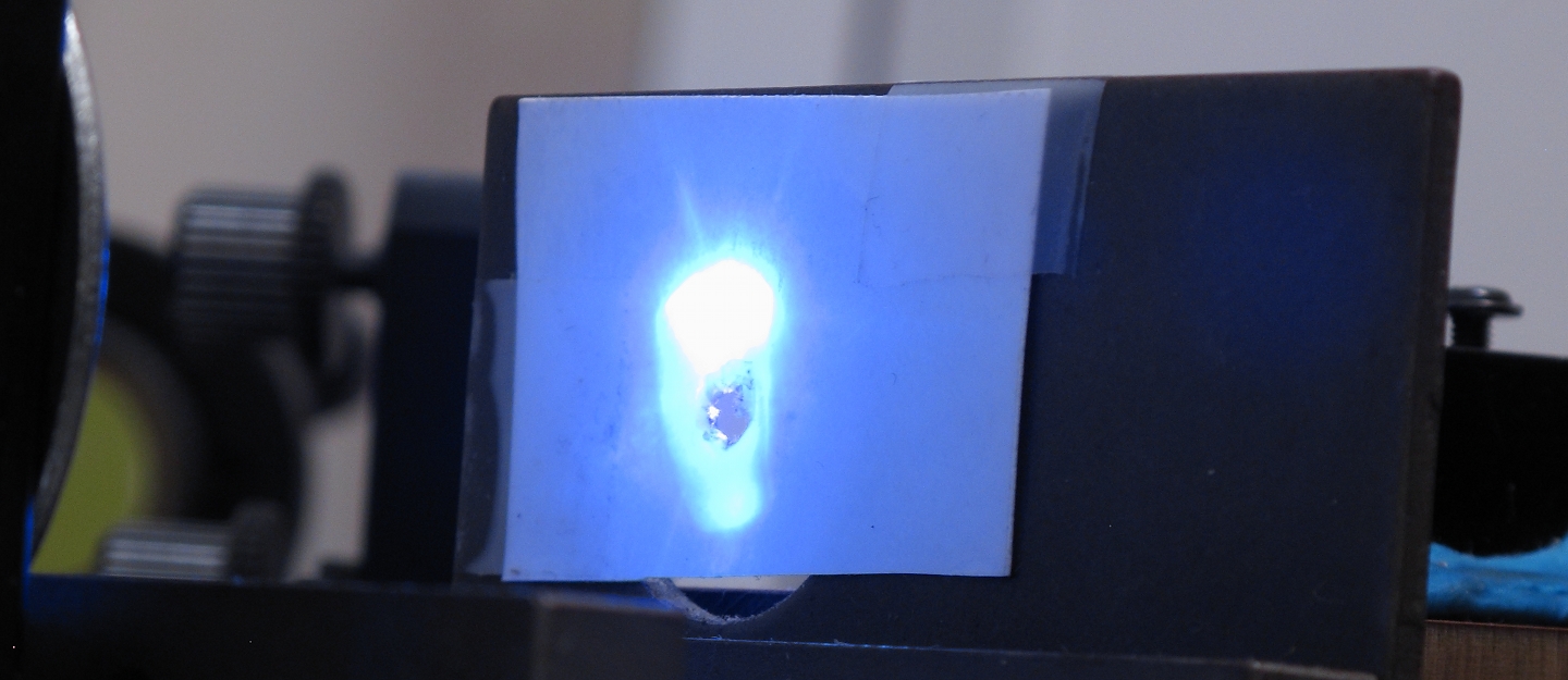
Here’s a close-up of the coherence check I am currently using, which is a method I learned from Milan Karakas:
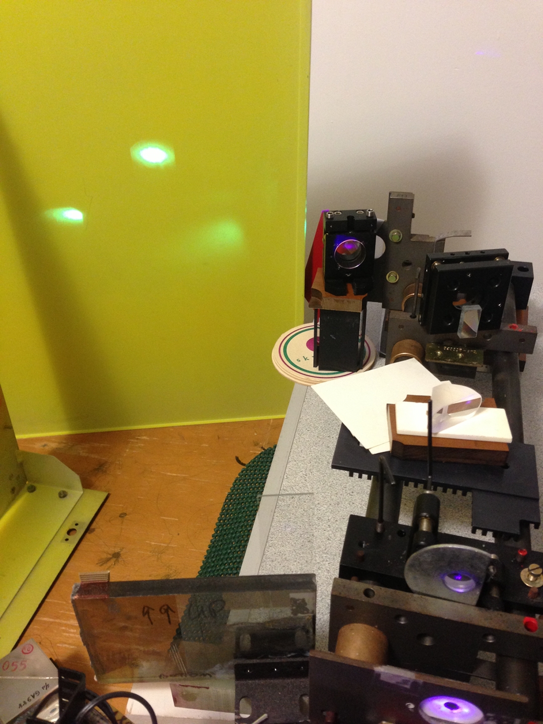
(As mentioned above, the main beam bounces off the sapphire sewer-camera window. The difference here is that I have positioned a microscope slide at least 30 cm away from the sapphire window, and I am letting it reflect onto the fluorescent screen in the background.)
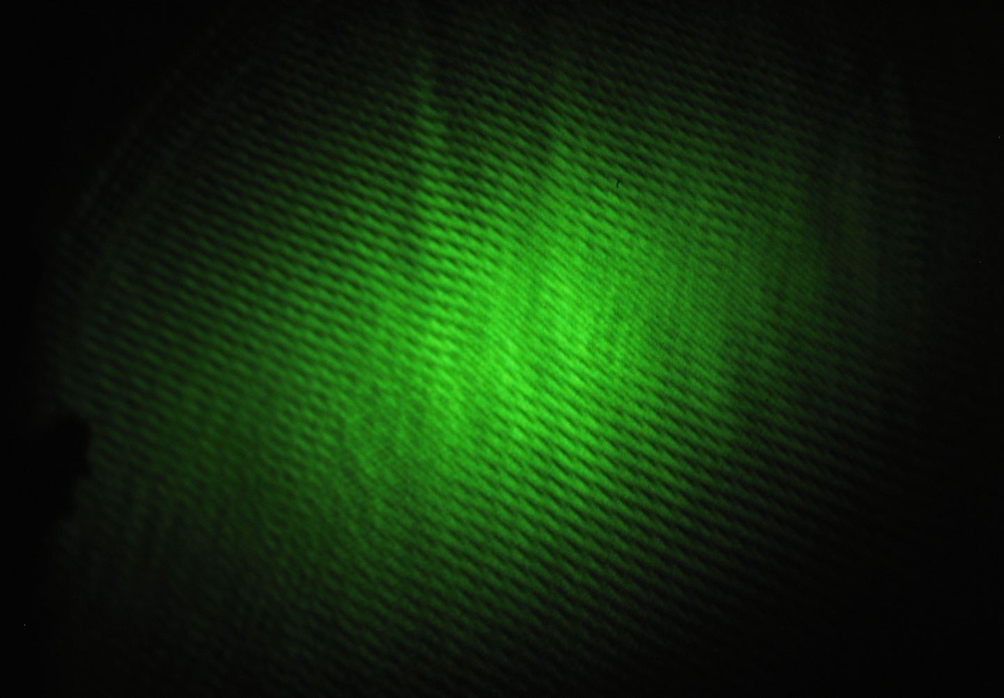
Here are three photos of output patterns. The first is a typical pattern from the new Michelson; I took it from a slightly oblique angle, which is why the bullseye is not circular. The second is a typical pattern with just the sapphire window in place, before I added the microscope slide. The third is a typical pattern with both the window and the slide in place, when the output of the Michelson has good fringe contrast. It is clear from other photos (not shown here) that when the laser is not cleanly locked, the contrast of the window-and-slide pattern is minimal or absent. Fortunately, periods of good lock last significantly longer than I should need for an exposure on ordinary film or plates.
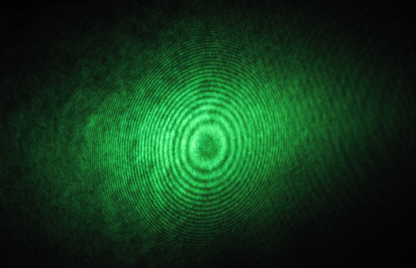
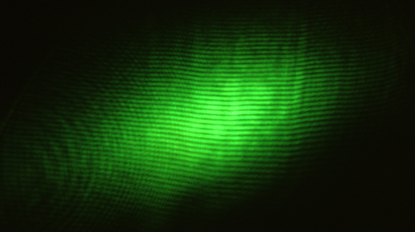
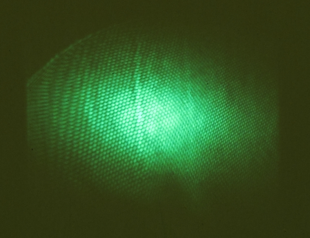
(The third picture is only 1040 px across because the pattern is so small, and I couldn’t get the camera very close to it. The background of the third image is not as dark as the background on the first two because the room lights were on when I took it.)
(Addendum, 2013.0520) Because the microscope slide is about the same thickness as the sapphire window, which can create a confusing patern, I changed it out for a fused silica plate that is ~3 mm thick. Here is a photo of the new pattern, with good fringe contrast from the Michelson, and with the window and the silica plate about 20 cm apart:
(A bit later I increased the spacing to at least 13 inches [33cm]; the fringes look slightly different because I changed the angles of the two plates, but they are just as nice.)
This all matches what I would expect, and the new fringe photo resembles one that Milan showed me. I am somewhat relieved. (I still don’t entirely understand some of what I was seeing a few days ago, but that’s life.)
Dan has also provided some old Holotest film, which is apparently somewhat fogged but should be just fine for initial testing, ...when I have time to build a holography setup. That may be a bit of a while, as there are many other things I need to accomplish in the near term.
(2013.0522)
I removed the extra mirror from the Michelson, restoring it to its original condition...
...to see what would happen. What happened was that it became significantly easier to achieve locking, and the locking became stable over much longer periods. Here is an uncompressed video (about 55 seconds, just under 71 MB), showing the patterns.
Next: can I actually make a hologram with the beam from
this thing?
(Not unexpectedly, I also make some changes to the setup.)
To the Main index for my research
Contact:
You can send email to myfirstname (3 characters; no “H”!) at the same domain that’s in the URL of this page.
Last modified: Tue Feb 24 23:39:13 EST 2015