(2015 Feb 24, &ff)
I recently purchased a box of 6 PFG-03M plates (made by Slavich) and a JD-4 developer kit from Integraf. These plates are sensitized for red light, and are intended for use with red diode lasers (typically around 650 nm); but essentially all silver-halide emulsions are sensitive to violet and ultraviolet light, and I was confident that I could get at least something with light at about 405 nm. It was largely a matter of power level and exposure time; with the laser putting out 150-250 mW I anticipated exposures of a few seconds for transmission work, and even less for reflection holograms.
Now that I have a moderately stable platform, as I’ve written up on the Sideline connected to this Broadside set, it seemed like a good time to take a stab at it. The big violet diode laser is only moderately stable, but the coherence requirement for a reflection hologram is far smaller than the requirement for a transmission hologram, and I thought I had a fair chance.
I was right. The photos here show the first plate I tried. It is also my first-ever attempt at holography with a diode laser — previously, I have only ever used HeNe lasers — and my first-ever successful white-light-viewable hologram. (I’ve tried once or twice in the past, but the plates I used did not really have sufficient resolution even with red light [longer wavelength], and the results were minimal.)
I haven’t measured the output from the violet diode I’m using, but it is supposedly capable of 500 mW or more; I think I am running it at about 150 or maybe 200 mW. (I will eventually check, to be certain.) The beam was not spread out quite enough, and was “hot” on the lower part of the plate, but the object (an old aluminum mirror mount) was largely in the area where the beam was strongest. The exposure I used was about 5 seconds, and it was enough that the entire plate turned black almost as soon as it hit the developer. This is a good sign; if you’ve read the first page in this set, you know that one of my objectives is to be able to expose a plate in 2 or 3 seconds at most, and it looks like I’m more than there, at least for little white-light-viewable plates: this one was considerably overexposed.
(In looking around on the Web, I found ample suggestion that overexposure decreases diffraction efficiency, and that may account for part of the washed-out appearance of the plate in the photos. When I get a chance I will try this again with the laser at lower power, and with a shorter exposure.)
I took the first photo below when the plate was still slightly wet. Some dust settled on it while it was drying, as you can see in the second photo. The adjustment screws were a few millimeters away from the plate during the exposure, but at least one of them is visible. Although that’s only a minimal indication of coherence, it is certainly pleasant.
My second plate got scratched when it and the object I planned to use (which had a lot of sharp edges) fell over as I was starting to set it up. I did get a hologram, but even aside from the scratches it is not as successful as this one. OTOH, I think it may show part of the setup very clearly, and that’s a good sign.
At this point I have a partial proof of principle, and probably one of the first holograms ever made with a violet diode laser running in excess of 100 mW. This is just “baby steps”, but baby steps are crucially important, and not anything to be ashamed of, as too many people are; we are, most of us, very poorly trained in this regard.
(2015.0226)
Meanwhile, Tommy Johnson notes that although the limiting resolution of PFG-03M plates (it is given as “more than 5,000 lines/mm” on the Geola site) is quite respectable, the resolution requirement for the type of hologram I made the other evening is double the requirement for a transmission hologram. Hans Bjelkhagen notes, in one of his papers, that a reflection hologram (which involves beams at 180° to each other, and thus minimizes the fringe spacing) taken with light at 400 nm requires at least 7600 l/mm resolution.
Tommy also points out that the Integraf folks show a particularly simple transmission setup on their Website, which I hadn’t noticed, and which I will be trying. The tradeoff is that transmission holography has much more stringent requirement for coherence length; I still have a lot of work to do on stabilization before I mess with this.
W/r/t stabilization, Jeff Hecht has pointed me to a page at one of the forums (I’ll provide a link when I get a chance) where people are discussing 445 nm blue lasers as possible sources for holography. That led me to the mention of a stabilization method someone used with a blue diode; it’s one I tried some time ago, with only indifferent results, but I will probably try it again, now that I’ve had more experience with the methods I discuss on the previous pages of this set. I have three more violet diodes on order. They are rated for considerably lower power than the one I’ve been using, but they’re handy in that they are all the same model, so I will be able to compare results. (There is a fine set of typical spectra on the datasheet for one of the high-power violet diodes. It gives 4 representative mode structures; they vary greatly from one unit to the next.)
If you were wondering, the reason why I didn’t go with a blue diode to begin with is simple: although they are available at rather high powers, and although it is clear from the technical specifications that PFG-03M plates are reasonably sensitive at 445 nm, many of the blue diodes do not have clean transverse mode structures (there is at least one with STM output, but the one I saw listed is only rated for 50 mW). Aside from that, an AgX emulsion is significantly more sensitive at the shorter wavelength of the violet laser. The chart, unfortunately, stops at 500 nm, but at that point it is trending upward. In any case, I have a longstanding fondness for violet light, so it was easy to rationalize the decision. ;o)
I do have a moderately powerful red diode, but it’s from an early DVD drive, and it is at a wavelength that is well beyond the sensitization peak of the PFG-03M emulsion. If I were willing to spend >$100 I could get 30 PFG-03C plates, which are sensitive out to about 700 nm, but I want to be sure I know what I’m doing before I throw that much money at this.
(2k15.0306)
I recently acquired two “pet toy” lasers, low-power 650nm red diodes, for $2.99 apiece. In testing, I found that these rapidly settled down, and both of them showed coherence length of more than 6". That made me curious, so I tried my two violet laser pointers, and was somewhat surprised to find that neither of them produced any fringes, even after some warmup time, and even with path difference of less than 1". It seems not only that small violet diodes are quite different from small red diodes, but also that they are quite different from high-power violet diodes.
I then tested a 200mW green DPSSL module that I have. This module works the same way as a typical green laser pointer; the pump energy is provided by a NIR diode laser, which runs at about 796 or 808 nm depending on the crystal host for the next stage. The pump light from the diode laser is focused into a small crystal that contains neodymium ions. That crystal lases at a wavelength of about 1.064 microns in the IR. (Again, the precise wavelength depends on the crystal type.) Its output is bounced through a nonlinear crystal that converts 2 IR photons to 1 green photon at half the original wavelength. The nonlinear effect is proportional to the square of the input power, so if (just for example) there are two longitudinal modes operating, one of which is generating twice as much power as the other, the doubled output from the stronger mode will be four times as powerful as the doubled output from the weaker one. This is not enough by itself to guarantee good coherence length, but it may help improve the contrast if there are in fact a few (very few) competing modes.
[I have wondered why people don’t just put the pump diode’s output directly into a doubling crystal. The sense I get from reading about it is that the transverse mode structure of the output from the pump diode is not well suited to this (probably the longitudinal mode structure as well), and that doubling the output of the Nd laser proceeds at much higher efficiency. It is, nonetheless, an interesting idea.]
Two other things are important here. The first is that although the little crystals involved are quite a bit larger than diode laser chips, they are still small enough that the mode spacing is fairly large. The second is that the gain bandwidth of the Nd ion is much narrower than that of any ordinary diode laser. This makes the wide mode spacing of the crystal more likely to select one or a few longitudinal modes. (If you want a better understanding of this, or any number of other laser-related issues, you may want to take a look at Dr. Rüdiger Paschotta’s excellent encyclopedia.)
The net result is that I had no trouble obtaining fringes with the green module, though it took some time to settle down, presumably because of all the sources of heat in it, and all the related effects. (The wavelength of the pump diode changes with temperature; the efficiency of the doubling crystal has some temperature dependence; both of the crystals change size with temperature, which changes the mode structure; the gain of the Nd laser may possibly change with temperature...)
I have some old plates that are sensitive to green
light, and I will be testing with them when I get a
chance. They do not have as much resolution as the
Slavich plates I tested with the violet laser, so I will
be trying transmission holography with them. I may also
try using them for transmission holography with the
violet laser, if they are still good.
(2015-0311/12)
Late this evening I made two attempts at transmission holography, using the simplified setup mentioned above. I did not get the object illuminated well enough, so only a small portion of it (the bright arc at lower right) is visible in the reconstructions here, but it is clear that this worked. I’m fairly sure that I was looking at the wrong side of the plate when I took these two photos; the bright arc should be at lower left, as it is in the third one, below. This, unfortunately, is because the plate was facing away from the object when it was exposed.
I was able to see part of the support structure as well, more clearly than the object (it is visible above and to the left of the object, particularly in the photo on the right above), but I have not yet been able to photograph it well. I will try again when I have a chance to make a better viewing setup.
One way you can tell that this is a transmission hologram: view it with a non-laser (broadband) source. Here’s what it looks like when I view it with a white LED:
I have some rather ancient BB-640 plates, which I thought until late this evening were BB-520. I also have a 200mW green DPSSL module. Because I thought that the plates were intended for green light and because I wanted to see whether they would still work (I knew they were old, but I didn’t remember that I’ve had them for 7½ years), it seemed reasonable to try them with the DPSSL, so I did. I let the laser warm up for quite a while, and it produced a behavior I had not seen before: for some time it produced 2 beams instead of one. My first exposure was for about 3 seconds, with the weaker beam. It produced essentially no result, so I exposed the second plate for about 20 seconds. That produced a hologram, but it was so pale I could barely see it. By the time I returned to the setup after processing the second plate, the laser had returned to putting out only one beam; I gave the third plate about 37 seconds, and it worked. Here is what the setup looked like —
(I had aimed the laser at what turned out to be a bad angle, and it is very difficult to photograph the plates. My apologies.)
I exposed the fourth plate for about a minute, and the image is a little bit brighter, but I managed to drop it before I could photograph it, and there is now a big chunk missing from it. Sigh. It would be just as difficult to photograph as the third one was, though, because I didn’t change the angle of the laser.
The literature that comes with the plates claims that they become insensitive after a few weeks. It provides two methods for restoring the sensitivity, and I may dabble with one of those; but the plates are not intended for use at 532 nm in any case, so I think I will try them with the violet laser when I get a chance, and if they require an uncomfortably long exposure I will try restoring them.
I should note, btw, that I used JD-4 chemistry on these plates. It seems to work reasonably well.
Addendum, 2015.0508:
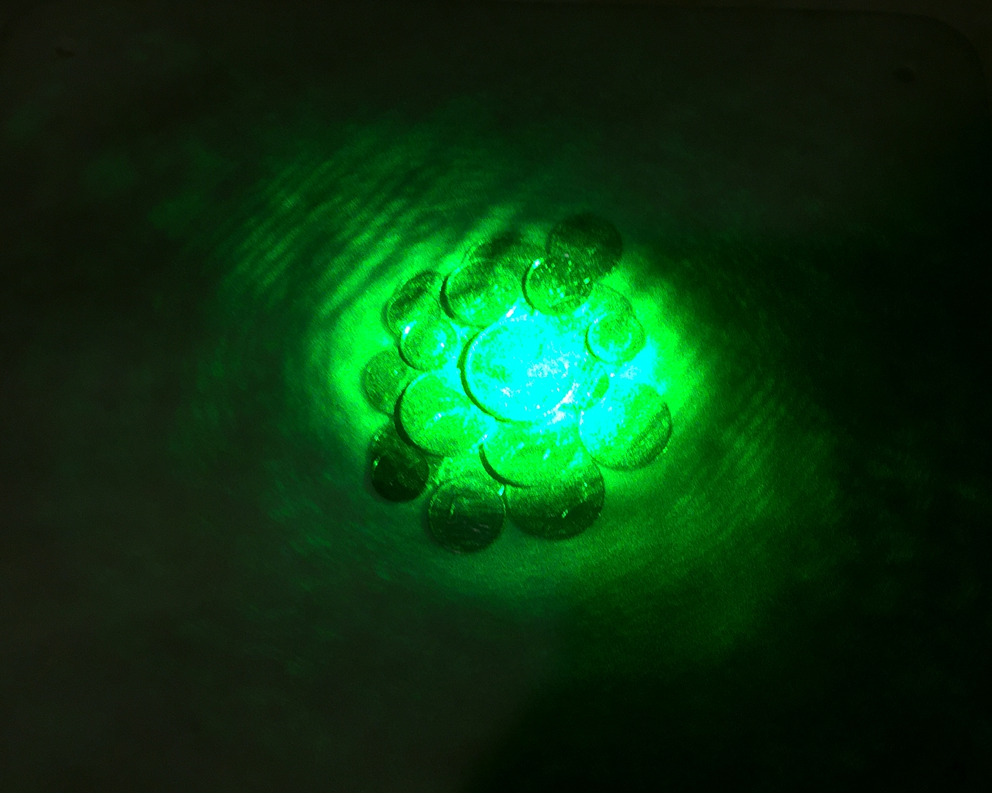
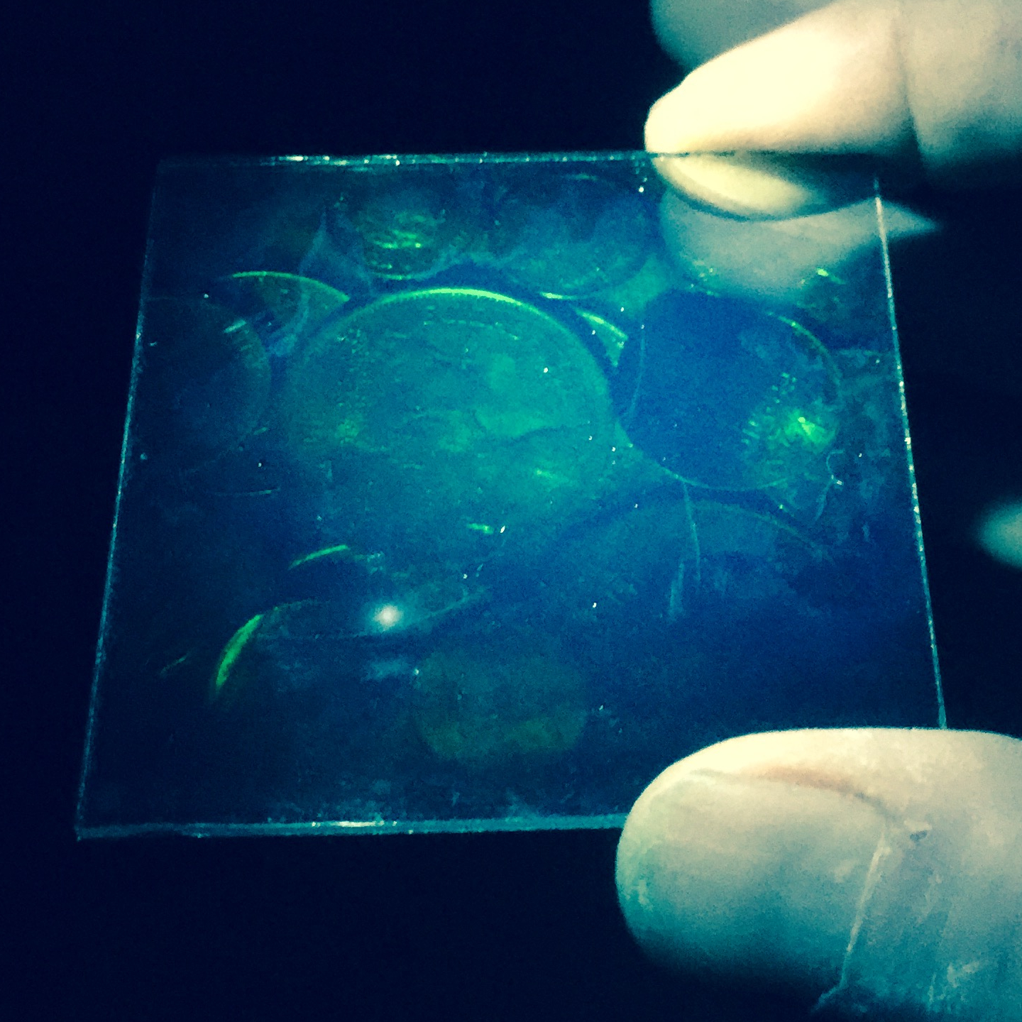
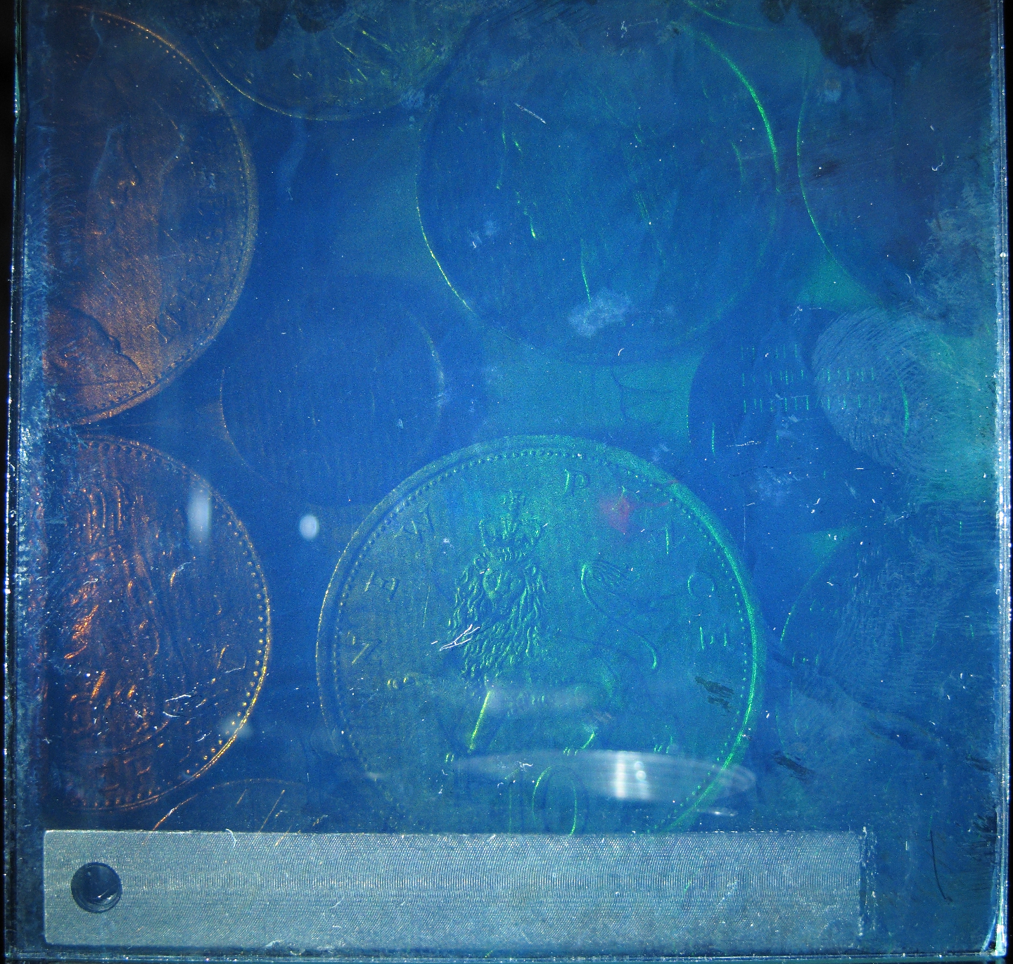
Two nights ago I tried this again. My first attempt failed, for unknown reasons, but it was with a subject that is probably better suited to transmission holography than reflection holography, and I hope to try it again when I have a good setup for that. (See below.) My second attempt was with coins; it succeeded, more or less. I think the cloudiness in the photo is partly because of the aged-out emulsion, but there may be processing issues as well. The beam from the green laser module was not spread out as much as perhaps it should have been, so the illumination of the scene was uneven. I will take steps to ameliorate that, next time. The exposure this time was 60 seconds (by the clock, not just by slow counting). I got lucky: it was late at night, there was very little traffic, and this type of setup is less sensitive to slow motions than a transmission setup. (I will need to redo the stabilization yet again before I will be willing to risk trying transmission holography here.)
I took the reconstruction photo with the Canon G-11 rather than with my phone. There are some reflections; at close quarters it is not easy to avoid them. In addition, I had to stand the hologram up against something; this accounts for the broad band of machined aluminum at the bottom of the image. (I am thinking about alternatives that will be less obtrusive.) The fingerprint at mid-right is on/in the emulsion, and I doubt that I can get rid of it. I wear rubber gloves when I process these things, and I think perhaps I will start wearing rubber gloves when I make them.
Here is a monochrome version, at higher contrast:
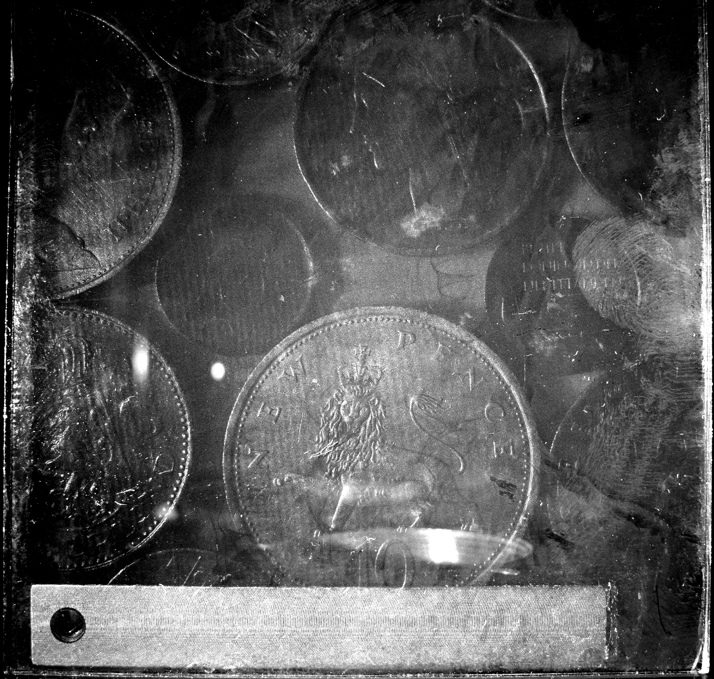
If you want a better sense of the resolution of the image, take the monochrome version and change "14c" to "27c". The detail is pretty nice. I am not entirely sure what causes the narrow bands that slant down the image; they appear on several (if not all) of these.
2015.0509, early AM
For some time I have been saving the wads of cotton that are in bottles of various supplements and occasional medications. Early this past evening, on a hunch, I stuffed a quantity of this in between the mylar balloons near the bottom of the antivibration stack. It had the result I was hoping for: the cotton damps out a fair amount of vibration, and in particular it prevents the stack from oscillating much when the house shakes. (In terms of resonances, it seems to decrease the Q of the balloons significantly.)
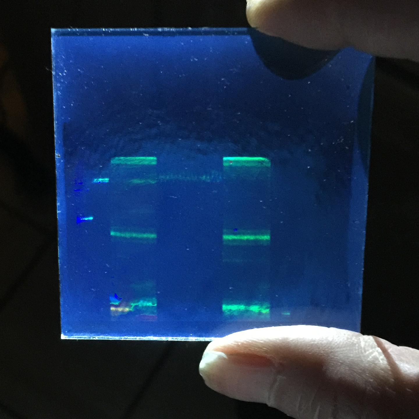
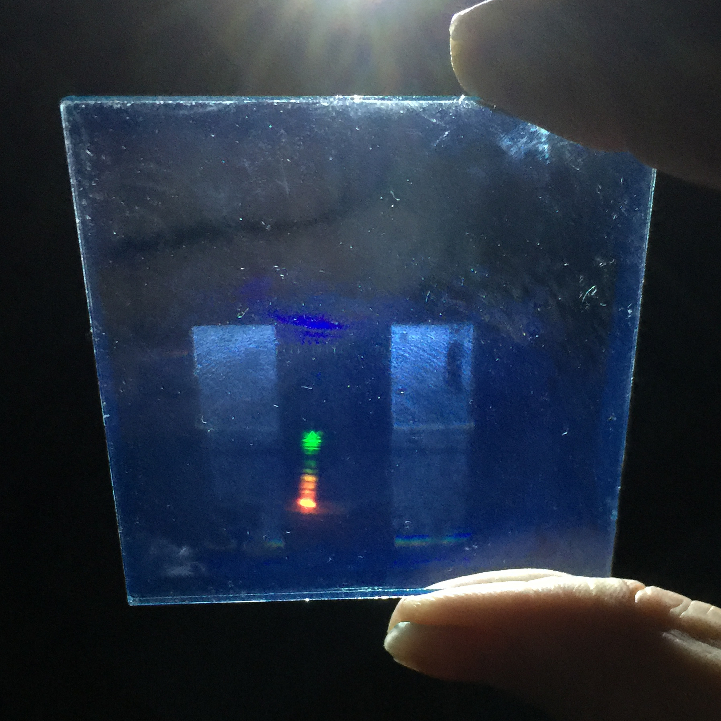
During the past few hours I tried 3 more exposures, all of which failed. Two of them were attempts at transmission holograms, with exposures of 2 minutes and 3½ minutes. When I examine the second of these with the white LED I can see areas of diffraction, rainbows, but they are somewhat indistinct. They are also hard to photograph, but this image shows a little bit of what I’m referring to — blue/green/red near the center of the image. (The red and green bars further to the right are actually transmission holograms of the edge of the plate.)
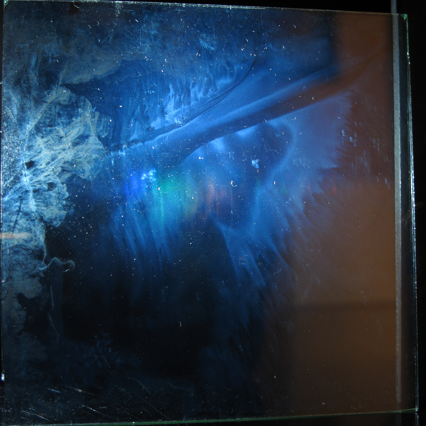
(The stuff that looks like abstract science-fiction illustration is all problems with the emulsion.)
When I illuminate the plate with the green laser I can see only the tiniest hints of anything (aside fruom the cruft), and there certainly doesn’t seem to be anything resembling an image. It’s a little bit better with a red laser, but again there isn’t anything like an image. Still, the rainbow fringing I see with the white LED tells me that something was recorded, which is a good sign: there was an unpleasant amount of traffic, and I’m sure the top of the platform shook at least a little during the exposure. (I have since had an idea for a plateholder, which I hope to build this evening.)
As mentioned, these plates don’t look very good, and I am more and more afraid that they have taken too much damage in storage to work well enough for display. They’re still good for practicing on, though, and perhaps eventually I will find other uses for them.
(2015.0510)
Several of the items in the setup were not as stable as
I wanted, so I have taken steps to firm them up. I
built a plateholder, put a base under the beamsplitter,
and stabilized one of the mirrors a bit better. In
addition, I added another piece of shielding against
air currents. I am hoping to try again this evening,
and will report results if there are any worth reporting.
More as it transpires...
To the page on which I develop a viable stabilization method for this work v
To the Main index for my research
Contact:
Email: use my first name (only 3 letters; no “H”), at the domain that’s in the URL for this page.
Last modified: Sun May 10 16:58:43 EDT 2015