(Addendum, 13 May, 2008)
If you want the whole Megillah, just keep reading. If you
don’t need to see the entire process, you can
skip to a page that contains only recent information.
(2003 Jun 10)
Some time ago I was given a small Paragon electric kiln. It served as my main kiln for a while; but we acquired other kilns (an L&L J-23 and a lovely old Dyna-Kiln), and eventually the elements in the Paragon wore out. I decided to convert it to gas so I’d have a modest test kiln with which to learn something about fuel firing, and also to continue learning about glazes that are fired in reduction or to cones higher than 9.
I ditched out the elements and made two extra holes in the side, one to serve as a flame inlet and one for a flue. I built a chimney from fiberboard.
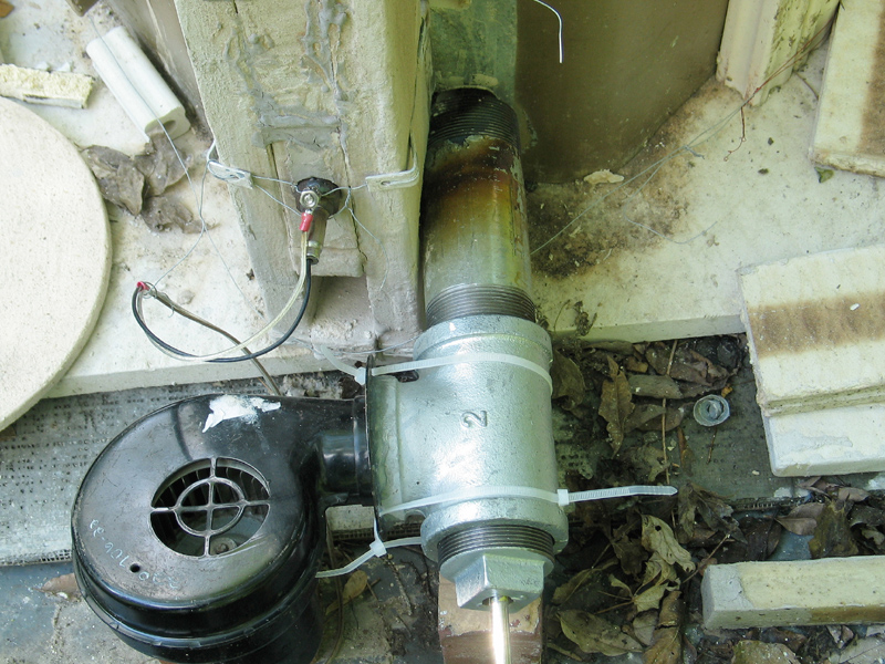
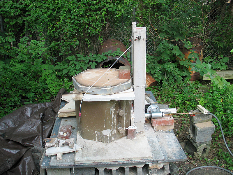
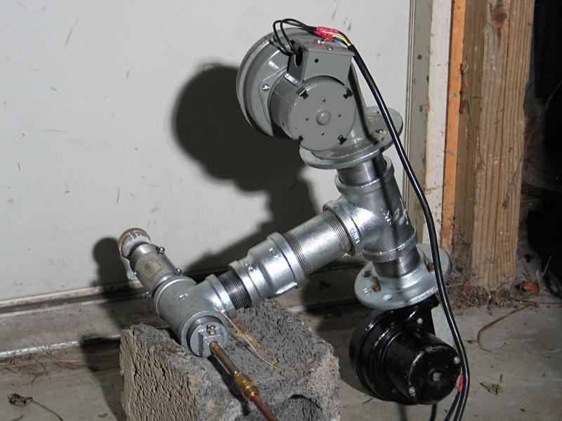
I was going to use my small burner, which I constructed for use with a tiny test kiln last year, but Melissa McDowell gave me a weed burner, and I decided to make a forced-air burner from that. I took a small centrifugal blower and attached it to some two-inch galvanized pipe fittings that I bought at the hardware store; I also put an adapter on the thing so I can run it off something larger than a little propane cylinder. (I hate disposable anything.) This combination seems to work reasonably well for a first attempt. Here’s what it looks like:
I can’t show you what this looks like in action (yet), but here it is in position at the kiln:
The kiln sits on an inch of fiberboard, which sits on a
half-inch nylon-reinforced concrete slab from the hardware
store, which sits on a thin steel plate for support. (Even
with the nylon in it, concrete isn’t all that strong when
it’s so thin.) The whole business rests on a
sand-and-cinderblock plinth. I have all of this outdoors
because I do not have adequate ventilation in my studio and
I don’t care to asphyxiate myself. (I keep a tarp over this
entire thing when the weather is wet; the steel plate helps
keep wetness from the ground away from the kiln and the
fiberboard it rests on.)
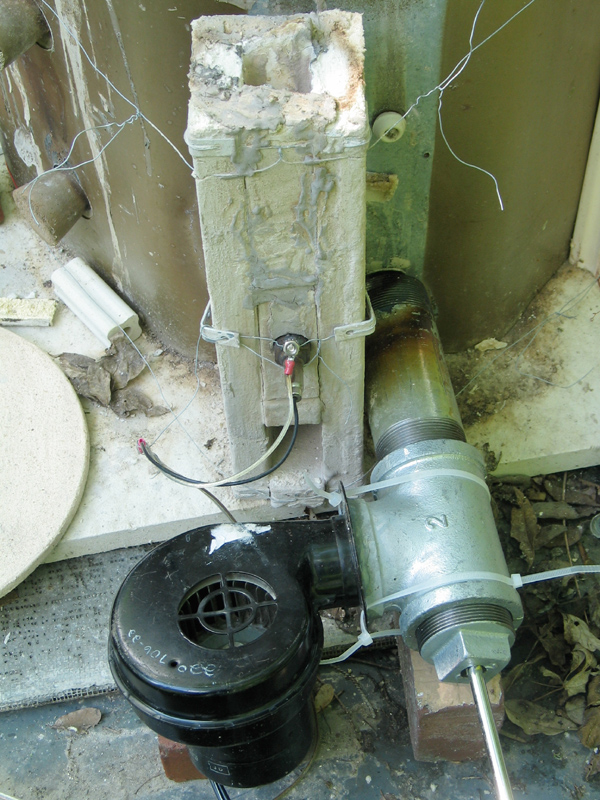
Here’s a bit of detail of the burner and flue in position. To the left of the burner, sticking out of the flue, you can see the back end of the automotive oxygen sensor that I’m using to monitor the redox conditions during firings. (I’d been vaguely wondering whether there was any way to use an automotive sensor in a kiln, but hadn’t done anything about it. Then Roger Graham, in Australia, did it and wrote it up for Ceramics Monthly. They used to have it in their “Must Reads” section, but I can no longer find that entire part of their Website. (Sigh.) In any case, it definitely works!)
I’ve only fired this kiln once so far, and I had to stop the firing after only 4 hours; it reached cone 013 in about 50 minutes, and by the time I turned it off it was hot enough to fuse a cone 10 clear (just barely) to a matte surface, probably just under cone 3. I have every hope that it will reach cone 10 without any real trouble. The oxygen sensor makes it really easy to tell when I’m oxidizing and when I’m reducing (see the recent "must read" article on this at ceramicsmonthly.com), but I’ve had a very difficult time trying to achieve a neutral fire. Perhaps with practice, or maybe using some sort of servo control system... For those who are interested, I kept the voltage from the sensor around 0.6 to 0.75 volts for what I hope was mild reduction, and below about 0.2 volts for oxidation (mostly below 0.1 volt). It’s really easy to do this by adjusting the gas flow and/or blocking part of the air inlet of the blower with a flat piece of cardboard or plastic. (Suction holds it in place.)
I am thinking about spraying a centimeter or so of refractory on the inside of the kiln to enhance the insulation; the kiln is really rated only to about cone 8 as it stands, and I don’t want to damage it. I’ve already coated it with ITC 100HT, and will either apply ITC 296A over that, or will redo the coating(s) if I add more insulation.
One thing I don’t yet know is whether I can get the flame
to fill the inside of the kiln well enough to give me
reasonably uniform temperature throughout. I’ll have to play
around with it, but that’s part of the fun of learning.
(2003 July 7 or so)
I have now fired the kiln a second time, toward the end of June, as a result of which I rebuilt the burner. The brass, which is somewhat delicate (and slightly melted, ahem) is positioned further back inside the long tube (which is now 8" long instead of 6" as it originally was), and I’ve put a pipe cap on the end with many holes in it to act as a flameholder. There’s a stainless-steel scrubby-pad behind the pipe cap, to assist in mixing and to slow down the flow of gas so the flame doesn’t fall off the burner and go out. (I learned this with my previous burner, and it has now come in handy once again, but keep reading for some reasons to avoid it.) I have also bolted the blower onto a pipe flange for a more secure attachment.
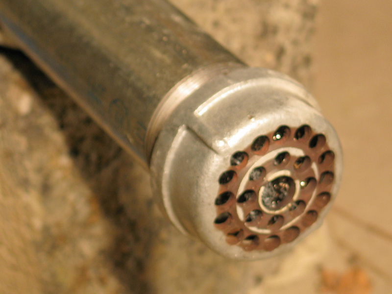
Here are two images. Sorry the detail of the flameholder is slightly out of focus; eventually I’ll try to take a better shot.
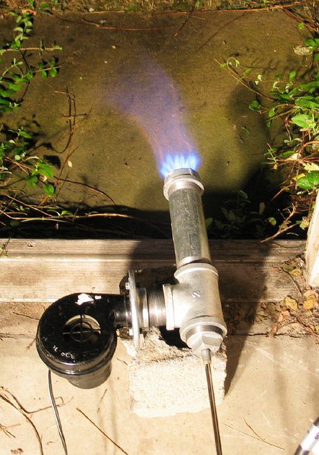
(If you want a considerably larger view of the burner operating, click the small picture and then change ".c6.jpg" in the filename of the resulting image to ".c14.jpg".)
You’ll observe the discoloration of the business end of the burner in the second photo. Given the fact that it has operated for a grand total of about 90 seconds at this point, I don’t know how long it will last; but pipe caps are cheap, and I can always make a slightly better flameholder from another one. (I do intend to clean it up a bit, and coat it with ITC 213 metal protectant, so it could actually last quite a while.)
When there’s light enough, and time, I will take photos of
this new burner at the kiln, though I hope there won’t be
much to see — I’m trying to set things up so very little
flame escapes.
(2003 July 27)
Every time the flame flashed back into the burner, which it did from time to time, it burned the crap out of the stainless-steel scrubby pad stuff in there. Eventually it wouldn’t run correctly at all, so I replaced the burnt scrubby with a new one, which I moved back a bit so it would be away from the flame. I also tweaked things a bit, and got the parameters adjusted so that the flame stopped flashing back.
Before I tried firing again, I lined the kiln with a thin layer of high-temperature fiber blanket, and painted ITC-100HT on the hot face. When I got it going, everything went well for just about two hours, all of it in fairly heavy reduction, after which the flame flashed back, and I couldn’t restart it. (No real surprise there.) When I examined the burner later I found that the front plate was partly melted; the burner had been pushed up against the kiln, and the business end had gotten extremely hot. Fortunate that it was just a cheap pipe-cap. (If you are going to engage in learning exercises, it’s good to do it as inexpensively as possible, consistent with safety and with actually getting the information you’re after.)
Here’s a photo (added on August 9th, 2003) —
I’ve decided that my next attempt will be with the smaller of the two commercial venturi burners I’ve got. It’s rated for 75,000 BTU/hr, which is gross overkill, but I’ve found that it throttles back very nicely.
I’m not a draft-and-chimney expert, which is part of why I was hoping to use a forced-air burner: the chimney is there mostly to put the exhaust in a convenient location and to direct it upward — it isn’t really necessary. With a venturi burner, on the other hand, you have to ensure a decent draft. If it fails to draw enough, the worst case is that the flame sits mostly outside the kiln, doing you no good at all. If there’s too much draft, the kiln will probably run in oxidation all the time because it will be pulling in too much secondary air, and it may not heat sufficiently well to reach peak temperature. This is a fairly delicate balance, and I’m somewhat uneasy about it — it is conceivable that the kiln could require six feet (a little under two meters) of chimney or even more in order to work well.
As of this afternoon, I’m constructing a new chimney that
is taller and wider than the one in the photos; it has
over two feet of active height, and I just hope that will
prove to be enough. At some point, I’ll try to take photos
of the burner, the chimney, and other salient bits, and
I’ll put them here or in the next section, when there is a
next section.
(2003 August 03)
I tried running the kiln with my commercial venturi burner,
as I mentioned in the previous section. The new chimney
seemed to draw at least moderately well, but when I tried to
turn up the gas even a little, the flame pushed out of the
top of the chimney about a foot or a foot and a half. It
was, at that point, very reducing and not very hot. Also,
about half of it was outside the kiln, either in or above
the chimney.
It is possible that the flame inlet is too small, but in
fact that style of venturi burner is designed to produce a
long brushy flame, which almost certainly contributed to the
problem — the kiln is literally too small for the burner.
After almost 8 hours (I gave it a fighting chance) it didn’t
get any hotter than it has been during the previous
attempts, so I stopped the firing and retreated to the
drawing board and the Web.
[If you are interested in burners, you may want to take a look at
Ron Reil’s pages;
check out
Rex Price’s burners
while you’re at it, as well — they look
really good to me. There is also a book about burner
design, called Gas Burners for Forges Furnaces &
Kilns, by Michael Porter, of Seattle; it is full of
typos and errors, which is extremely unfortunate, but it
contains much good information and advice. Porter is the
person who figured out that the wire-feeder tip from a
MIG welder is just the right shape to be an extremely
efficient gas orifice, a fact that I took advantage of
here after I saw it mentioned on one of the pages I was
reading. (This project took place before Porter wrote
his book; I added some of this information at a later
date.)]
I decided to go back to forced air, but with the slightly
enlarged flue and the new (larger and taller) chimney, and
with a somewhat different burner design. This one is
modelled after the free-air forge burners that I mention
in the previous paragraph, with the differences that you’d
expect because of the blower — two concentric pipes instead
of just one, for example, with the inner pipe being the
actual burner, carrying gas and primary air, and the outer
one carrying secondary air.
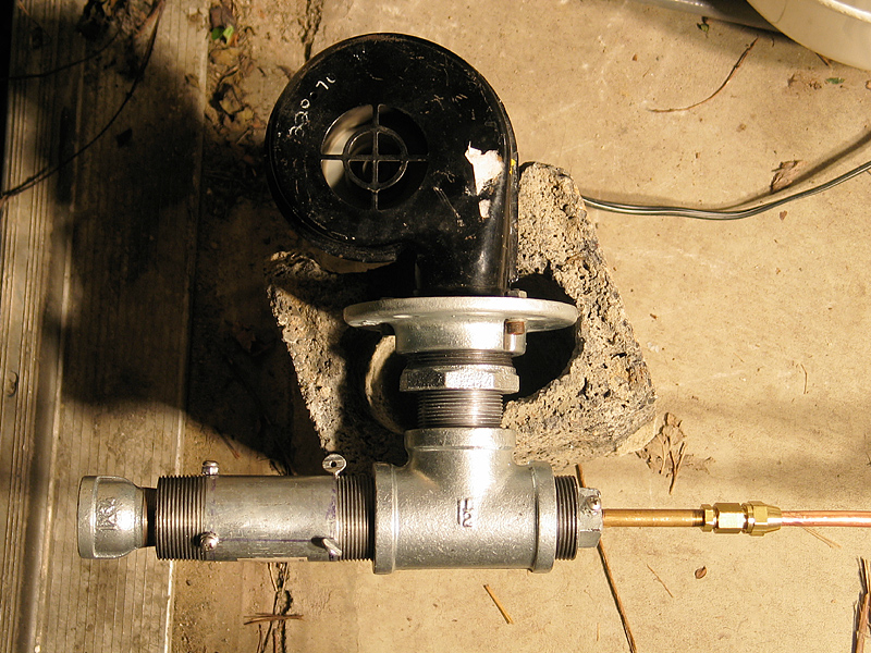
Here are some photos. First, an overview. The blower is at
the top, the gas feed is at the right, and the flame emerges
from the nozzle at the left. (I was calling it a flameholder
until Ron Reil suggested, in email, that there were good
reasons to refer to it differently. Seems that the term
"flameholder" largely refers to devices that slow down the
gas mixture by impeding the flow, which is not a happy
method — remember my flashback problem with the previous
burner design.)
Note that the majority of this design is built from 1.5"
pipe; my previous burners for this kiln were built from 2"
pipe (in fact, you can see that I’ve had to adapt the
blower flange, which is a 2" part, down to 1.5" so it
would fit the tee). I chose the smaller pipe size partly
so that I could be relatively certain it would match the
size of the flame inlet on the kiln, in case that was a
problem with the previous burners. (I don’t really think
it was, but I didn’t want to take the chance.)
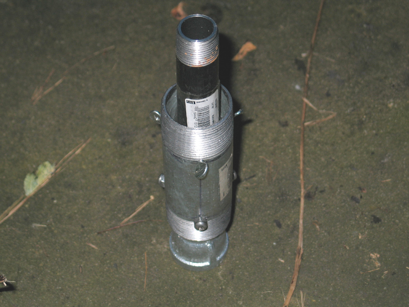
Here are the two concentric pipes I mentioned, unscrewed
from the tee section, and with the nozzle down on the
floor. Notice that the inner pipe extends into the tee
section much farther than the outer one. (I’ll get into
the purpose of this in a bit.)
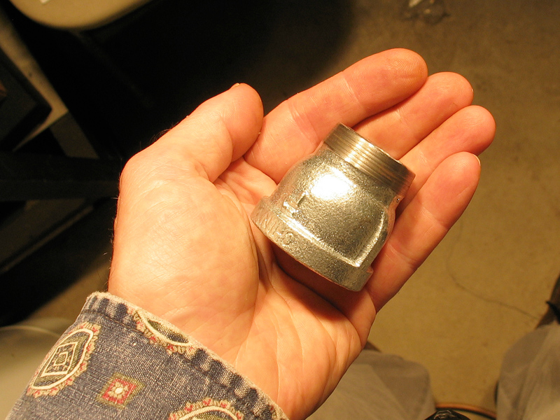
The nozzle is nearly invisible in that photo, so here’s
a picture of it. You can see that I’ve turned down the
flange on the narrow end.
The flame front travels at a certain speed. (This probably
depends on the gas:air ratio and various other things.)
While the mixture is inside the burner you want it to move
faster than the flame front does, so that the flame stays
outside where it belongs — if the gas mixture moves too
slowly, the flame flashes back into the inside of the
burner. This tends to heat up the burner rather than the
kiln, and is strongly deprecated. (Ahem.) When the mixture
reaches the end of the pipe, however, you want it to slow
down so that it is moving out only as fast as the flame
front moves in — if the gas mixture moves too quickly, the
flame blows off the end and you can’t keep the burner
lit. When you get it right, the flame front sits nicely at
the end of the burner.
The really good designs I’ve seen use fairly sophisticated
nozzles, but you have to have a forge to make a 12:1 taper
out of a piece of pipe. Thinking about what I needed and
what was readily available, I had a pleasant idea for a
simple one that turns out to work pretty well: I used a
pipe fitting, a 1"-to-3/4" reducer. Because the diameter
of the flowing column of gas has to increase in order for
it to fill the wide end of the reducer, the gas has to
slow down. I figured that it would slow down just about
enough, and I was happy to discover that it does. This
relatively crude arrangement probably isn’t as efficient as
a smooth 12:1 tapered pipe nozzle, but simplicity is not
to be sneered at. OTOH, I have some suspicion that the only
reason why this works in my design is that I have cold air
running along the outside of it whenever the flame is lit
— Ron Reil notes that there is some danger of melting the
nozzle if you are in free air, which doesn’t keep it cool.
(Mine gets red/orange hot, even with constant cooling!)
[Note, added on February 20th, 2005: I have been using
this same nozzle for about a year and a half now. I probably
should have coated it with ITC-213 metal protectant, but
I didn’t, and it is nonetheless still quite serviceable.]
I used a lathe to turn down the outside of the smaller end
of the reducer so that there would be room for the secondary
air to get past it. (As you can see in the overview shot and
in the first photo below, the base of the nozzle is
just at the end of the larger tube. If it’s too wide, it
gets in the way. If I’d used 2" pipe for the larger tube,
this probably wouldn’t be an issue.)
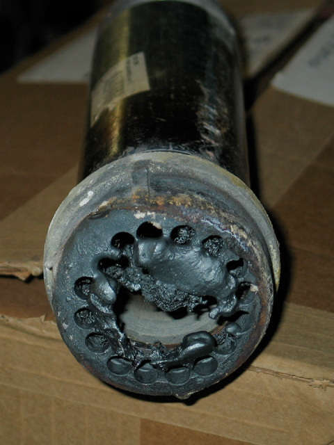
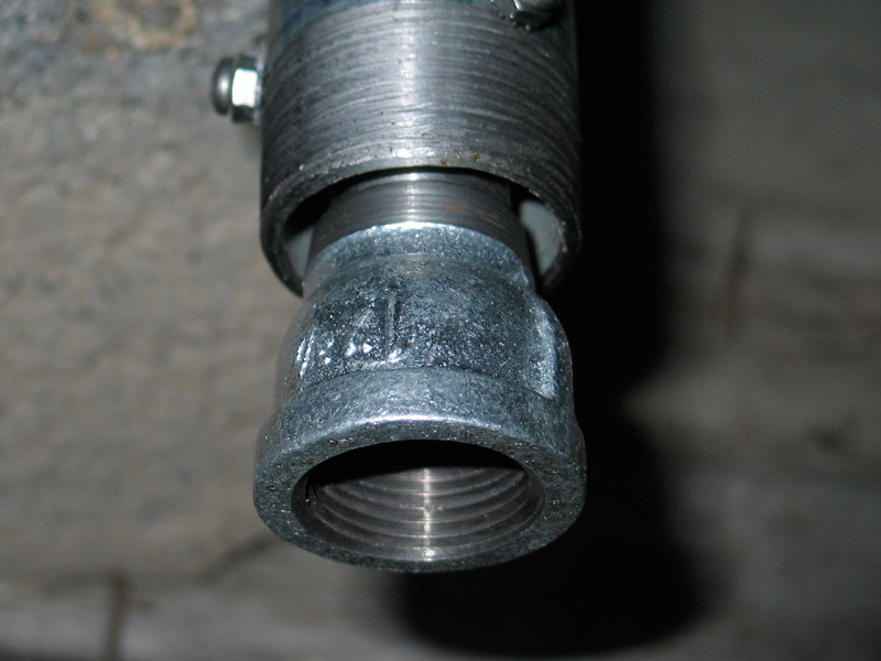
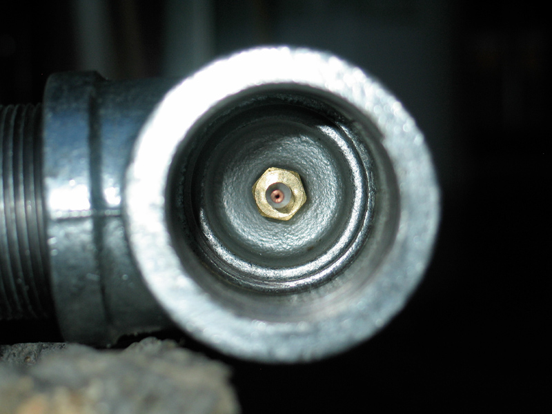
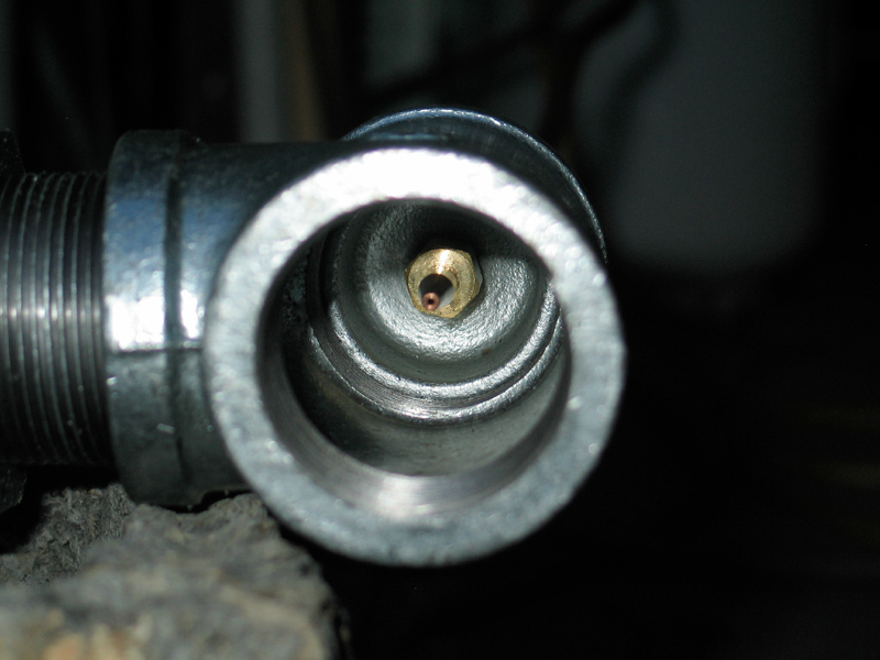
Here’s a look at the "business end" with the nozzle in
place, then again with the nozzle removed, and then two
views with the concentric tubes removed, looking a bit
more directly down the bore.
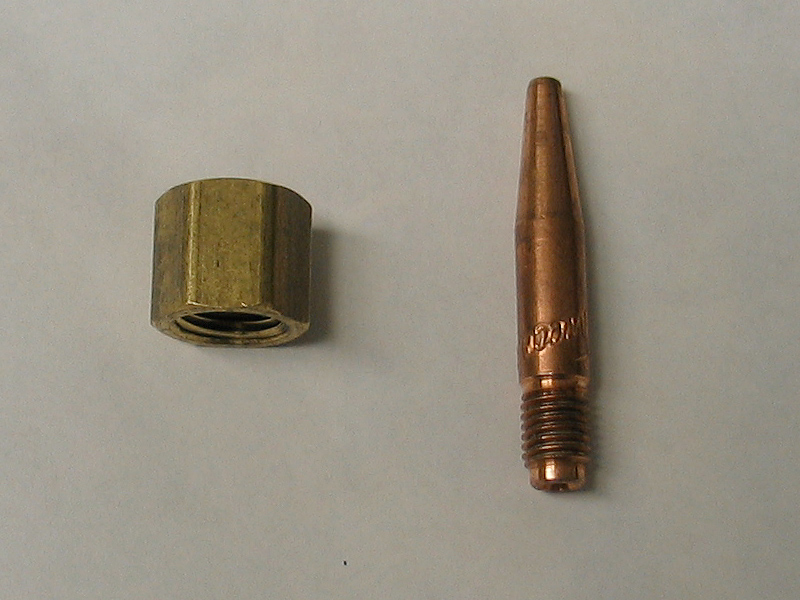
The copper and brass that you can see at the far end, down
inside, are the Tweco 14T tip that I’m using as a gas jet
and the pipe cap that it is screwed into. The Tweco tip is
intended for use as the wire guide on a MIG welder, as I
mention above. It’s rather amusing that it works so well
as a gas orifice. Here, anyway, are the Tweco and the pipe cap
on their own:
The pipe cap, in turn, is screwed onto the 1/8" brass pipe
that carries gas to the burner, which you can see in the
overview shot. (Remember, "pipe" is different from "tubing";
1/8" pipe is almost 7/16" outside diameter.)
This design is reasonably adjustable. I can slide the inner
pipe forward or back, which tends to change the ratio of
primary to secondary air. I can also swap out the inner pipe
entirely, and in fact I had to do that in order to get the
burner to operate correctly — the first one I tried was too
short, and there was so much primary air that I had to choke
off the inlet of the blower almost completely to get the
flame to stay lit. I thought about that, and decided that if
I could position the inner end of the burner pipe very far
back, less air would get into it. I put in a pipe that was
2" longer than the first one, and found that it worked a lot
better.
In addition, I can move the gas pipe in from the opposite
end, and thus push the pipe cap and Tweco tip into the back
end of the burner pipe, which obstructs the primary air even
more. This means I have three ways of adjusting the amount
of primary air, if need be. (I’m not counting the blower,
because I hope to run this burner with the blower wide
open.)
As you might guess, this device was pretty cheap to build. A
Tweco tip is about a dollar and a half, as is the little
pipe cap it goes into. A galvanized iron tee is probably
over three dollars; but I think all of the other pieces, or
nearly all, are under that. The fitting for the gas delivery
pipe is a couple dollars. I think the total cost was around
$20 or $25, not counting the tool I bought for putting a
flange on the copper tubing that carries the gas to the 1/8"
pipe at the back of the burner, and not counting the gas
hose that goes from the regulator to the burner — those are
regrettably pricy. I tried to keep machining to a minimum,
too, so the burner would be really easy to construct.
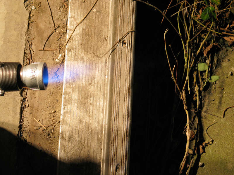
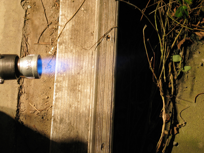
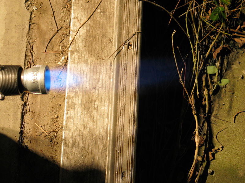
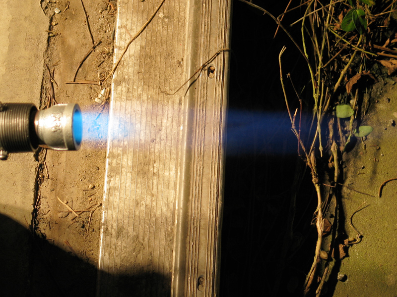
Here’s a series of flame pictures, at increasing gas
pressures. The first one, at the lowest pressure, is
a bit wobbly, but not horribly so. As the pressure
begins to increase the flame stabilizes very quickly,
and it remains stable up to approximately the highest
pressure I can get from this regulator.
Note that as the amount of gas increases, the flame gets
longer and eventually becomes more brushy; in addition, the
base becomes brighter and more greenish. The outside edge
remains blue because that’s where the flame begins to mix
with secondary air.
Inside the kiln, the flame will mix very thoroughly with the
secondary air, which will tend to make it more oxidizing (or
less reducing, depending). This means that I can use more
gas, and get more heat, before I push over into reduction.
(Note, added November 4, 2003 — As it happens, I’ve
discovered that in practice this design starts reducing at
fairly low pressure settings. If we number these photos 1
through 6, I usually run the burner on 2 or 3. I’m probably
going to add a second blower, to give myself a bit more
working range.) [Note, added December 24, 2004 — I did,
indeed, add a second blower; see the "Second Blower" section
below. I also put a pressure gauge on my regulator; I find
that I get moderately strong reduction at about 8 and
¼ psi, neutral-to-oxidizing flame at perhaps 6.5 or
lower. I have operated the burner with pressure as low as
4.5 psi or so with both blowers on, but I’m more comfortable
with at least 5 psi. If I really want to bring the heat up
slowly I turn off one blower and reduce the pressure to 4
psi or a little less. Even that isn’t slow enough for some
things, though.]
I didn’t run the burner very long to take these photos,
perhaps two minutes, but I did turn it all the way up.
Even so, within a minute after I turned off the gas I
could touch the nozzle for a moment without burning
myself. I’m sure it will get a lot hotter when I run it
for hours at a time, but that’s to be expected. (Note,
added later: As I mention above, it gets quite hot in
operation; but it cools very rapidly when I turn off the
gas flow, and within a minute or two I can easily touch it
without getting burned.)
(Note, added in proof, August 5th, 2003) —
I’ve added a bit of shim stock, wrapped around the gas pipe
where it enters the back end of the burner:
This holds the pipe in place better, and also centers it
better.
In the process of testing, I’ve found that the burner will
run at almost any setting of the gas regulator, and that
setting the position of the gas pipe probably gives me all
the control over the primary-to-secondary air ratio that I
could ever want. This is a very decent little burner, and I
hope it heats the kiln up the way I want it to...
The next section, when there is one, will almost certainly
report what happens when I attempt to fire the kiln with
this burner and the new chimney.
(2003 August 8)
The burner definitely works. I could begin to see a dull red
glow through the upper spyhole after only 9 minutes (!),
and the kiln reached cone 8 in just over 4 hours.
At that point it stalled, and I terminated the firing after
perhaps 4 hours and 45 minutes; but it is clear that we are
getting somewhere with this.
I went to buy a larger Tweco tip, but they were out of
stock, so I asked them to order one (it should be in today)
and I drilled out my extra one to a slightly larger diameter
as a stopgap measure. The drilled-out tip gives me more gas
flow and means I need more primary air, so I moved the inner
pipe forward and the gas pipe back to compensate. This
produces a noticeably heftier flame. The fact that I’ve
moved the inner pipe may allow a bit more secondary airflow
(the nozzle is now farther forward, and thus presents
less of an obstruction), which is good because I had to get
the extra primary air from someplace. (I’m still wondering
where I stashed my two larger centrifugal blowers, in case
the total airflow is no longer sufficient. Searching
produces various interesting results, but not what I’m
looking for. Argh.)
The next step is to fire the kiln again, with the interior
relatively unchanged. I’m not leaving the same glaze tests
in place, and of course I’ll need new cones this time, but
I’m planning on having everything else pretty much as it
was. Presumably, that will give me a sense of what I’ve done
to the burner.
Assuming I get farther than I did this last time, I will
then redo the configuration of the inside of the kiln. I’ve
concluded that having the flame go in underneath the bottom
shelf may be a mistake (it heats a region where there isn’t
any pottery), so I think I’m going to take the shelf off its
supports and let it sit on the floor. That, however, leaves
the flame pointing straight into the ware, so I’m also going
to put in something to direct the flame upward and possibly
slightly away from the flue. In addition, I want to revamp
the flame inlet, which is now irregular in shape and
somewhat larger than it needs to be for this burner; it is
letting some heat escape unnecessarily.
With luck I will fire this kiln again today, and will
report results here if they’re worth reporting.
(2003 August 08/09)
The title says most of it. I turned the kiln on at 8:30
after a couple false starts. (I tried to dry out the cone
packs, which I only made up last night, and a greenware test
tile; partially succeeded, but only partially... lost the
test tile and two of the four cone packs. The kiln was hot
enough that I was uncomfortable removing cones and bits of
cone-support porcelain with my bare hands, but not quite
hot enough to prevent me from doing it that way.)
I’m mostly adjusting the burner by watching for the flame
that comes out of the spyhole when I pull the plug or (when
I want more reduction) by just barely getting a bit of flame
to appear at the top of the chimney. I can sorta do this by
sound now — the burner makes a noise like continuous
distant thunder when there’s flame at the top of the
chimney, and kinda grumbles a bit when there’s just a small
amount of flame at the spyhole. The sound is more of a clear
rushing noise when the flame ceases to emerge at the
spyhole. The flame-watching technique only works at night,
because it’s hard as hell to see the flame during the day,
but if I can get another oxy sensor I should be able to fire
in daylight. (My old sensor seems somewhat erratic, and I
may have to replace it. I’d buy a new one, except that there
is a special pleasure in making good use of trash or surplus.)
If I haven’t misread the cone pack (if you have never looked
into a kiln at cone 10, please take my word for the fact
that it’s really hard to see much of anything in there even
with goggles on, and dangerous to look without them), it was
just at cone 10 when I turned off the gas at 10 minutes
after 11. That’s 2 hours 40 minutes from nothing to cone 10,
which is manifestly satisfactory. Next, I get to think about
the layout inside the kiln, to see whether I can improve it.
It also goes through propane maybe a bit faster than I’d like;
I suspect that I’m getting about three firings from a 40-lb
tank. Again, if I can bring up the overall efficiency, maybe
I’ll be able to improve on that.
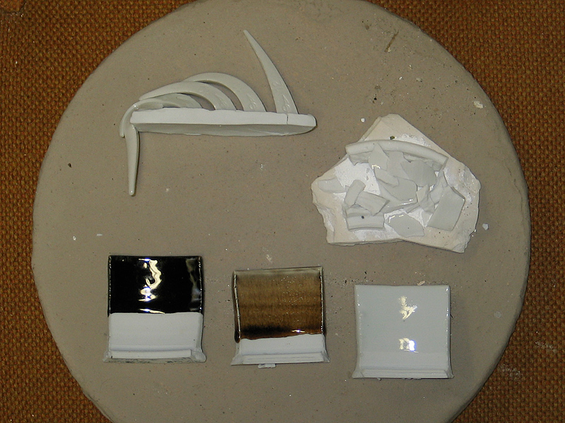
In the meanwhile, here are some photos of the results.
First an overview, showing the cone pack, the destroyed
translucent porcelain test, a tenmoku test, a Rutile Blue
test that didn’t turn blue (I suspect that I wasn’t reducing
hard enough for it), and a clear that’s pretty decent. The
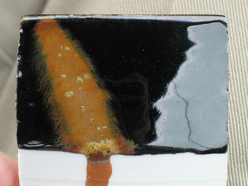
Tenmoku, which did just fine, is shown close up in the
second photo. The brown stripe that you see on it, with the
small groups of burnt-gold crystals, is a fairly standard
wash that I learned about when I was taking classes at
Seward Park Art Studio, in Seattle.
As you can see, I did indeed misread the cone pack: the
firing very nearly reached cone 11 — it is slumped over and
is touching cone 10; cone 12, all the way to the right, has
just barely started to move.
(2003 August 12)
I fired the kiln again today. It went to at least cone 10,
but it took a lot longer than the previous firing. There
were several reasons, possibly the biggest of which is that
I didn’t go back during the night last time and tarp the
kiln, as a result of which it got rained on rather heavily.
A lot of heat from this firing went into the last phase of
drying it out. (I did two previous drying runs, using a
propane torch, but they only got things started.)
Another reason why it took longer is that I was running it
in fairly heavy reduction through much more of the firing
than I needed to. In fact, I probably could have used
somewhat lighter reduction in general, and fired in neutral
toward the end. I think I’m either going to have to use
multiple cone packs, so I can tell when to stop reducing, or
put a pyrometer in. (I have some thermocouples, good ones
that Howard Davidson sent me, but they are quite small, and
I need to make protection tubes for them. I also need to get
the correct extension wire.)
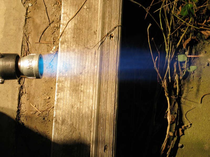
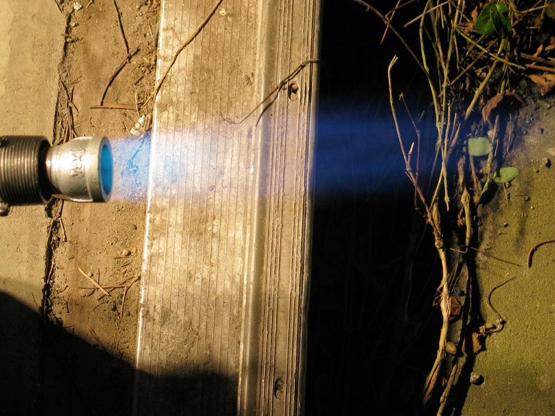
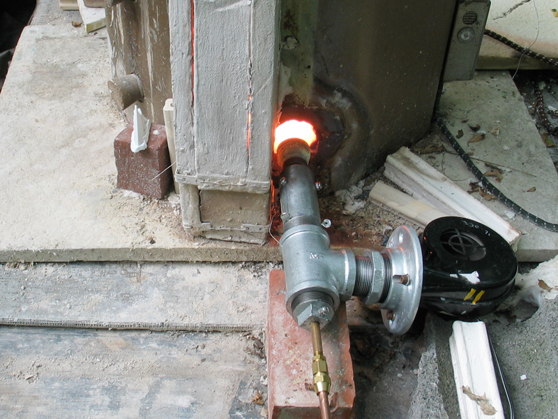
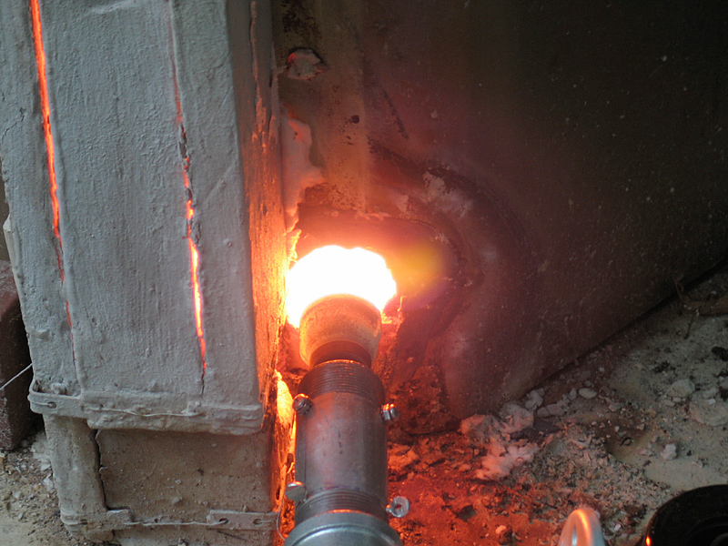
Here are some photos. First, the kiln on its plinth; then
the burner in action, with a close-up. You can see that the
chimney has some issues. (Please excuse the mess. I have
been putting my energy into getting this thing set up and
fussing with it to make it run, and I haven’t had much time
for prettifying it.)
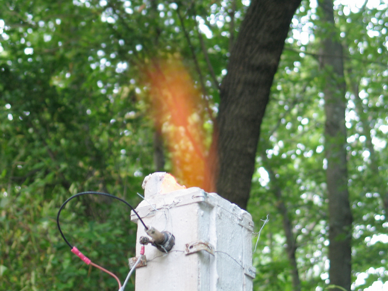
Here’s what the top of the chimney looks like when the kiln is
reducing moderately strongly:
When I get inside, I’ll put up some photos of the results
of the firing, assuming that they’re worth it.
(2003 August 21)
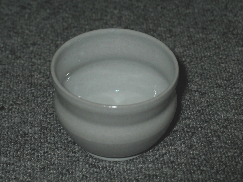
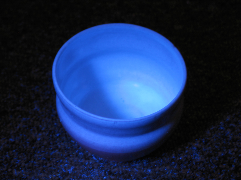
I got a couple nice glaze tests out of that last firing,
and a teacup that carbon-trapped... but not the glaze:
the body turned gray. It’s an odd and somewhat interesting
effect:
Not, however, what I wanted: that was supposed to be a nice
translucent porcelain. I conclude that one reason why the
firing took so long is that I was reducing very heavily,
using a lot of gas and not getting much heat. At least I
got the other effect I was looking for — here is the
same cup under longwave UV:
I replaced the Tweco tip with a new one of slightly larger
diameter than my first one (though somewhat smaller than my
drilled-out special) and fired again today, taking a bit
more care not to over-reduce. I was not entirely successful
— the kiln was in heavy reduction for over an hour — but
even so it went up to about cone 10.5 in less than three
hours, and I got at least one good glaze test out of it. The
copper red is gray, however, and I have to think about what
might have caused that. (Over-reduction is the most obvious
candidate.)
I think I’m going to shorten the chimney and seal it better,
in the hope that I can get cleaner readings from the oxygen
sensor. It is clear that the readings I’ve been getting lately
were ’way far off from the reality of what was going on inside
the kiln.
In any case, it is now clear that I’ve got a working gas
test kiln, and that I can fire it in reduction to the cone
10-11 range; that essentially marks the end of this
conversion effort. Now I get to learn how to run it and
optimize it; I’ll probably report those efforts elsewhere.
(2003 August 24)
I’m taking steps to add a thermocouple to the kiln, partly
so I can use it in oxidation for crystal glazes and partly
so I can get a better sense of how fast it heats up and
cools down. In the meanwhile I’ve shortened the chimney and
tightened it up a bit. It is now drying.
I’ve also decided that it’s probably a good idea to avoid
firing greenware unless I do a really long preheat, using a
propane torch as a small burner — the kiln heats up so
rapidly with the big burner that even very dry and fairly
thin greenware has a tendency to explode in it. (Voice of
sad experience.)
(Continuing, 2003 November 4)
I built a little amplifier for the thermocouple, so I can
read it with an ordinary digital meter (a Type S
thermocouple puts out only a few millivolts at 1250°
celsius, and much less near room temp, so I use an
instrumentation amplifier chip to multiply the voltage by
100), and I can now track the temperature during the firing.
I find that it goes up extremely steeply during the first 5
or 10 minutes, no surprise, and that by the time the kiln
gets to about cone 9 it is going up by perhaps 100 degrees
per hour. I’ve taken to writing down the temperature every 5
minutes during firings, and when the cone pack fell over, a
few weeks ago, with the kiln between 1160 and 1200 celsius,
I was able to finish the firing by doing a time/temperature
comparison with previous firings. This is not "the way it
sposeta be", but it was certainly preferable to terminating
the firing early.
Pursuant to Roger Graham’s excellent article in Ceramics
Monthly (which is at
this URL
if it’s still online), I now have two automotive oxygen
sensors on the chimney; but the readings I get from them
are rather strange. It takes them quite a while to come up
to operating temperature, for one thing; and if I fire
entirely in oxidation, I never see more than about 22
millivolts output. (I would expect to see 650-750 mV when
the kiln is in light to moderate reduction, perhaps
400-500 mV in a reasonably neutral atmosphere, less than
250 in light oxidation, and less than 100 in firm
oxidation. I do sometimes see numbers of that sort, but
not often. Having watched this a few times now, I think
that the sensor has to sit in a firmly reducing atmosphere
for at least a short time before it responds that way,
but I need to check that a bit more carefully.)
In the process of firing the kiln perhaps ten or twelve
times I have learned a certain amount of control, but the
path was somewhat fraught. If I keep it in light reduction,
it reaches cone 9 in roughly 90 minutes from a standing
start. If I keep it oxidizing, I get 6 or 8 firings from a
40-lb charge of propane; that drops to perhaps 4 firings if
I’m reducing, for obvious reasons. Unfortunately, because of
the trouble I’m having with the oxy sensors and the fact
that I often fire during the day, which means that I can’t
see any indications of flame at the top of the chimney, I’ve
had to learn to adjust the redox level by the sound.
Sometimes I forget that even a hint of throaty rumble in the
(generally smooth) rushing noise is an indication that the
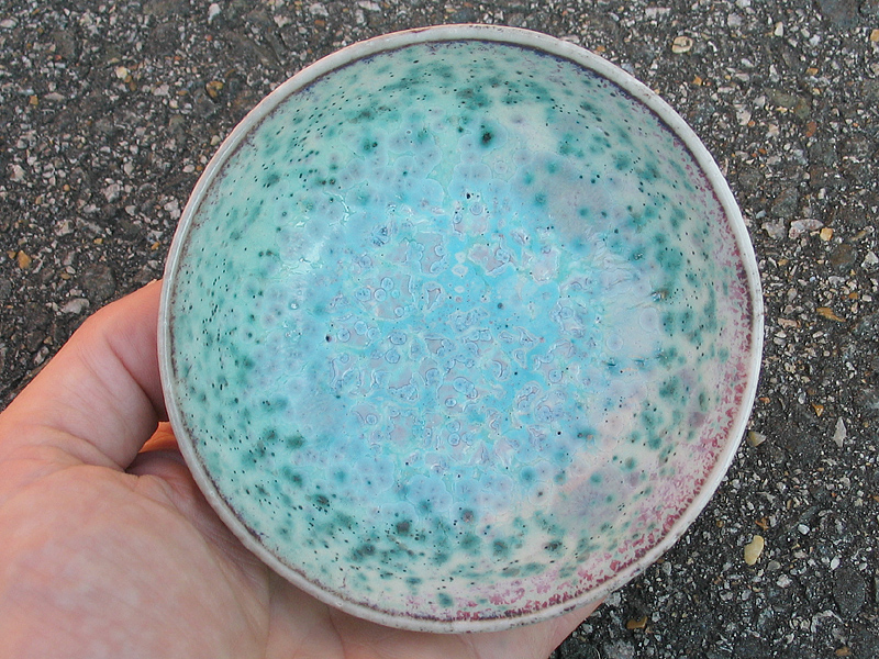
flame is reducing. I’ve done several firings of crystal
glazes, one of which went into reduction and produced
expectably muddled (though rather pretty) results —
At night it’s somewhat easier, though during the early
stages of a firing the sound is still the more reliable
indication. I’m just lucky that the difference between
oxidizing and reducing is actually audible.
While the burner is fairly well behaved, and the Type S
thermocouple is a real blessing, results like the bowl in
that photo tell me that there isn’t quite as much primary
air as I’d like, so I’m probably going to add a second
blower.
(2003 November 9)
I did, indeed, add another little centrifugal blower, and
once I got the burner adjusted, it ran fairly well. I
fired the kiln with it last night, and although I did
manage to get into reduction for a while (it takes a bit
of experience to get used to changes in the way these
things operate), I was very happy with the performance: I
ran the burner for about 80 minutes, and it took the kiln
nearly to cone 10, despite the fact that everything was
quite wet. (We’ve been having very wet weather here, and
the tarp I put over the kiln wasn’t enough to keep it
dry.) Here’s a photo of the new configuration:
(20 February, 2005)
I also shortened the chimney; it is only an inch or so taller than
the kiln. A forced-air burner system doesn’t really require a
chimney at all, and I have one mostly to keep the exhaust away
from the burner and the gas line, and to provide a place to put
the oxygen sensor.
(22 August, 2005)
Noticing that operation was slightly uneven with the two
small blowers, and wanting just a bit more air, I have
replaced that assembly with a single, slightly larger
blower. When I get a chance, I will photograph the new
arrangement, which works quite well.
(02 December, 2007)
Having read parts of Michael Porter’s book, I
conclude that I was very lucky to get a working burner
that actually seems to match my kiln fairly well; there
are many parameters, and lots of ways to make a lousy
design. As I say, though, I seem to have lucked out; it
now takes 90 minutes or so for the kiln to go from about
150° C (I preheat to drive off any water that
remains in the ware after I glaze it) to cone 10.
The kiln is in serious need of a new chimney and a new
fiber blanket coat inside, however, and is probably
nearing the end of its service life. We’ll see
how long it lasts.
For forges, at least, Ron Reil is currently convinced
that a blown burner confers no advantage at all over one
that is fed by venturi; I don’t know whether that
is also true of kilns, which present somewhat different
parameters.
(2008 Feb. 2)
I have just fired the kiln for the final time
in its current incarnation. Inside it were the
pieces of a new chimney, coated with ITC-100HT.
I took it to 1314° C in 105 minutes, thinking
all the while that I would run out of gas because
I used the dregs of a tank. I was wrong; there
was still a wee bit left when I turned off the
flow and pulled the burner away from the inlet
port.
I want to put a new fiber liner inside the kiln,
coated with ITC-100HT; I want to enlarge the
inlet port slightly, moving its center away from
the outlet port in the process; I want to move
the center of the outlet port slightly farther
from the inlet port if I can; I want to put
liners in both ports, to protect the kiln a bit;
and I want to see whether I can create a fiber
seal around the rim, so I don’t have to
keep worrying about leaks every time I fire.
(I should be able to get woven fiber rope,
specifically intended for this purpose.)
I will describe the rebuild and its results on
the next page in this set.
If you build one of these, please remember that the
flame emits copious quantities of UV, which isn’t
good for your corneas (or skin), and a hot kiln emits
copious quantities of IR, which can give you cataracts.
Wear welding goggles or equivalent protective devices
when you look in there! Also, be extremely careful about
gas leaks. Because I don’t have automatic shutoff
equipment on this burner, I stay with the kiln throughout
the firing. (Yeah, sometimes I leave long enough to take
a leak, but that’s about the limit.)
In closing, I would like to state my deep appreciation for
the work that people like Ron Reil, Michael Porter, and Rex
Price have done (a good deal of which Ron Reil has published
on the Web). I would have been completely at sea without
their excellent information.
On to the next stages of this work, in which I:
revamp this kiln,
build a larger burner,
and (I hope) eventually convert a nice old Dyna-Kiln to use
the new burner.
Email: a@b.com, where you can replace a with my first name
(only 3 letters, just jon, no “h”) and b with joss.
Phone: +1 240 604 4495.
Last modified: Sun Feb 17 00:36:44 EST 2013
I Think It’s About Time for a New Burner Design
About the Nozzle:
![]()
![]()
A Report from the Firing Line:
Success: Cone 10 in 2 Hours and 40 Minutes
Success Again, at a Price
Return to Our Previous Success Rate —
Learning to Fire the Kiln
Second Blower
Time for a Rebuild.
CAUTION
the Joss Research Institute
19 Main St.
Laurel MD 20707-4303 USA
Contact Information: