(30 December, 2003)
This is a followon to the page in which I describe my effort to resuscitate a rather dead nitrogen laser that we acquired on eBay a while ago.
I recently brought up a commercial dye laser (also found on
eBay), and discovered that although it is a fine device,
there are some limitations to what I can run through it. It
isn’t particularly suitable for some of the dyes I’d like to
test, so I’ve returned to the Avco head, to see whether I
can bring it back on line.
It has been some time since I worked on this laser. In the interim I’ve done various other things, and I’ve been cooking the nitrogen laser issues on the back burner. Several things have emerged; some of them are developed here. (I’m also working on another design, not a commercial head but a build-from-scratch, which I’ll document elsewhere.)
I’ve decided to make a change in the circuit topology:
This puts the switch directly on the laser channel. (The original topology had the main store mounted on the channel, and the switch mounted on the main store. See the previous page for details.) The main store, btw, is actually ~16 nf; I’ll fix the diagram when I have time.
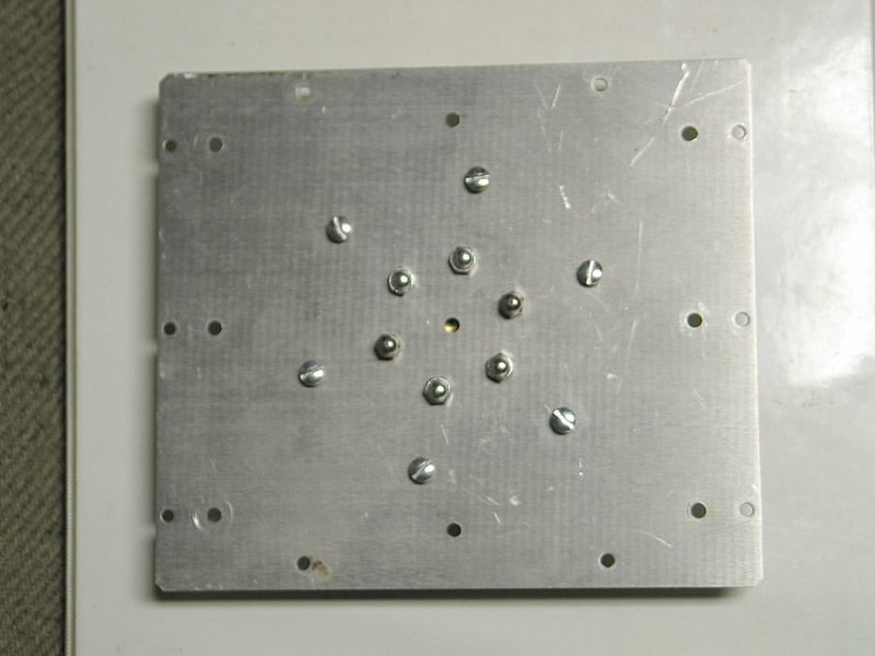
The advantage of mounting the switch on the channel is twofold: first, it means that the switch and cap won’t necessarily stick out as far from the backplate. Not only is that handy in terms of positioning the laser, but it probably reduces the inductances involved. Second, it lets me use "doorknob" capacitors as the main store or "dumper" cap. Here are eight doorknobs, each 2 nf, mounted on the backplate:
I was fortunate enough to have caps with broad, low-inductance terminations, though there’s a fair chance that the more usual narrow connections would have worked almost as well.
Here is a detail of the assembly, with caps and switch in place:
You can see the transparent file folders that I’m using as insulators (hey, they were available), and the two large white wires that go off to the trigger unit. (Very lovely 60-kV-rated wire.)
I will be putting a vacuum regulator on this head, so that I can adjust the pressure. If I presume, for simplicity, that it will perform optimally at 100 V / Torr cm, and if I figure that the channel width is 4 cm (see next photos), I need 4 kV on the channel at 10 Torr, and 8 kV at 20 Torr. Unless I’m charging the "peaker" caps extremely rapidly, I doubt that I can get much more than 8 or maybe 12 kV across it, so I need 20-30 Torr. The vacuum regulator goes down to 10 Torr, which is just fine.
I’ll report results on that when they become available; in the meanwhile, here’s a cell full of 7-Diethylamino-4-Methyl-Coumarin, first by roomlight and then caught with a pulse going into it:
(My apologies for the quality of the pictures -- it was fairly late, and I was holding the camera with one hand and the trigger switch with the other. I’ll provide better images later on.)
Note, added in proof, 2004 February 03:
Here are some photos that show a dye laser that I’m
pumping with this head, and a photographic tuning curve
for Rhodamine 6G.
(2004 February 03)
It eventually occurred to me that I had made
a significant error when I rebuilt the laser.
To wit, I was putting positive HV on the cathode.
Nitrogen lasers being what they are, it ran; but
I suspected that I could get better results with
the correct polarity, so I decided to swap it
around.
At about that same point, however, I was having
a certain amount of trouble getting the spark
gap to trigger, and I also managed to lose one of
the 2-nf dumper caps. (The cracks are not huge, but
they are clearly visible in the larger version of
the picture.)
I changed out the GP-15 for
a more recent GP-15B while I was replacing the cap,
thinking that perhaps the GP-15 was nearing the
end of its useful lifetime. Alas, although the newer
gap triggered nicely at first (at least with the
power supply "backwards"), when I corrected the
polarity I was unable to get it to trigger. At all.
I then spent quite some time investigating our
trigger units (one TM-11, old style, and three
of the newer TM-11A design). I’m still not entirely
certain about the issues, but I have decided to
rebuild the laser again, and I’m revising the
topology back to what it was originally. I was
going to insist on operating the gap in what the
literature on it describes as "Mode A", in which
the trigger pin and the "adjacent" electrode (the
one that surrounds it) are positive, but that
would have involved a certain amount of hanky-panky
because the end of the gap with the trigger electrode
would have been at 30 kV, face down (as it were),
with the trigger electrode inside the capacitor
bank.
Milan Karakas has convinced me to try, instead,
triggering in "Mode B", in which both the trigger
pin and the "adjacent" electrode are negative. This
puts the trigger electrode facing out, which is
much more convenient, and allows me to maintain
this area at or near ground potential except during
firing, so I won’t need any isolation between the
TM-11A and the switch. Here’s a revised schematic;
sorry it’s a bit rough.
Here are some photos that I took today, showing
intermediate stages in the rebuild. The first two
show the baseplate of the new assembly, which
attaches to the cathode rail. Sorry they’re a bit
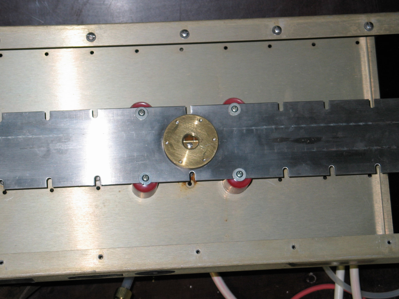
blurry. The next two show the rail itself, at the
attachment point, without and then with the protective
insulator.
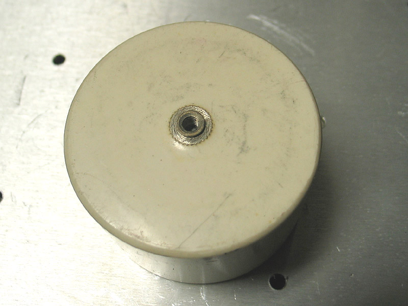
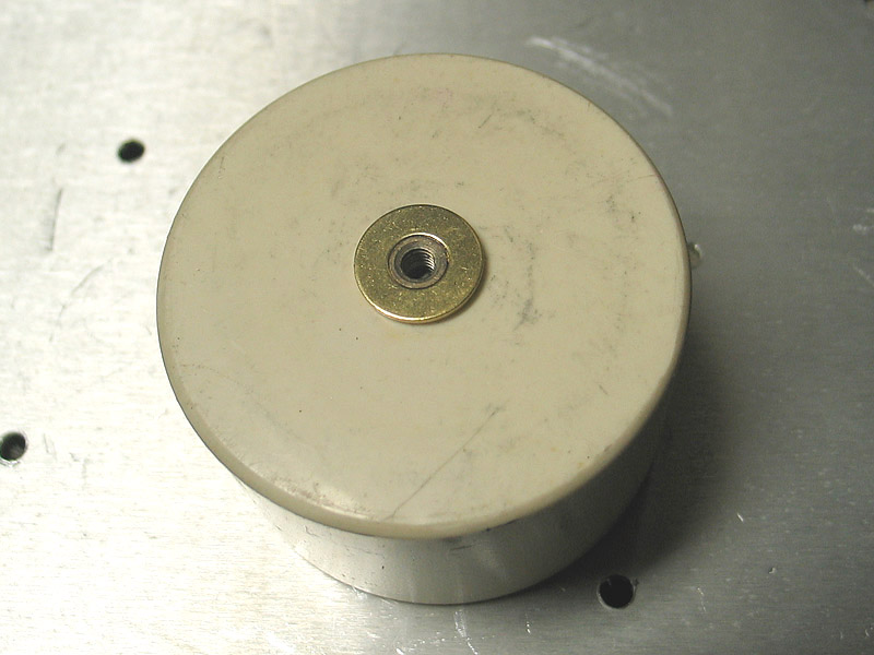
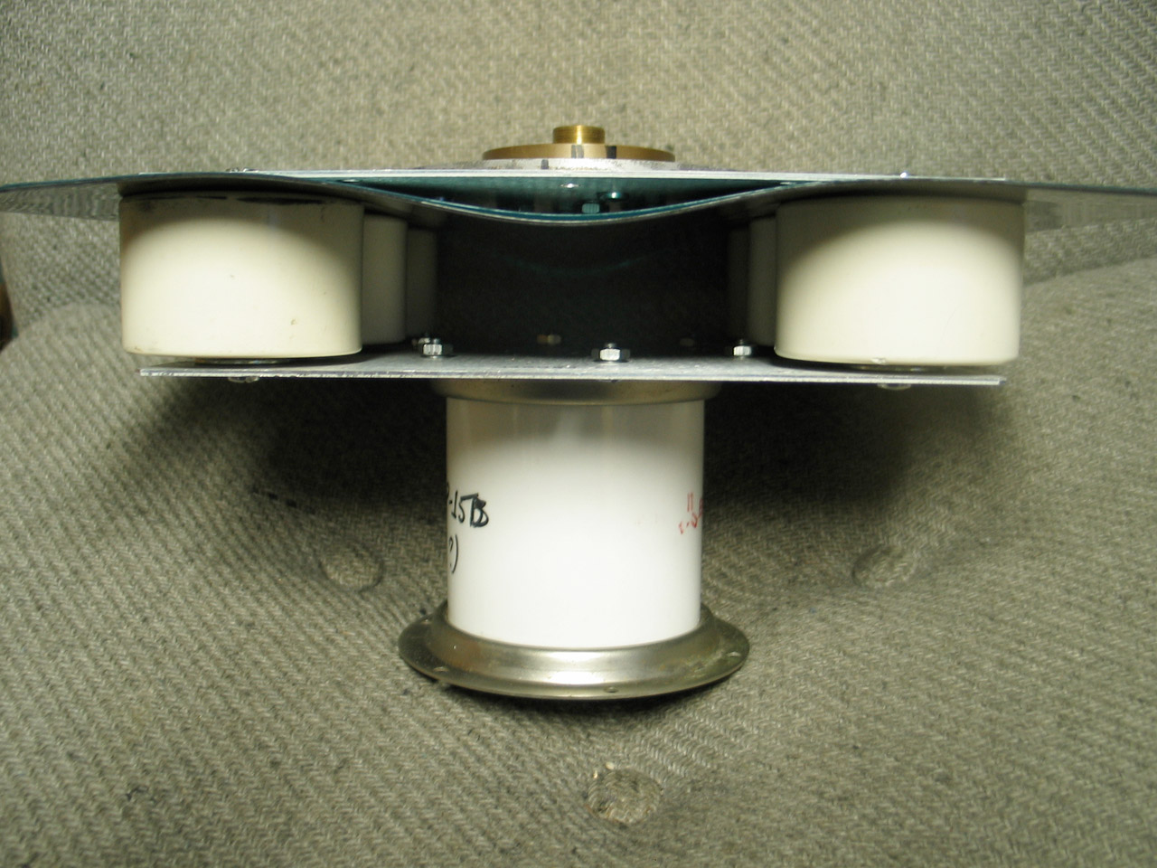
The next two show one of the capacitors; they are
not quite as nice as the 2-nf ones I was using
previously: the termination is considerably narrower,
which means that it has higher inductance. At these
speeds, that’s a big issue, and I’ve been reluctant
to use these at all. I noticed, however, that if I
clean any excess epoxy off the shoulder, they are at
least half as wide as the really good ones, and
should do; a washer allows me to make good contact.
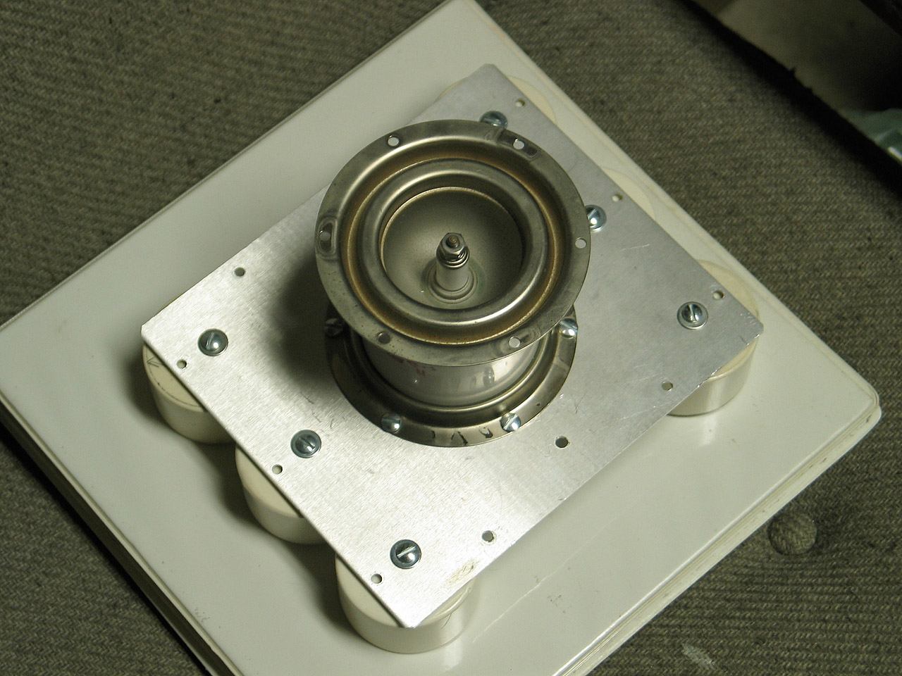
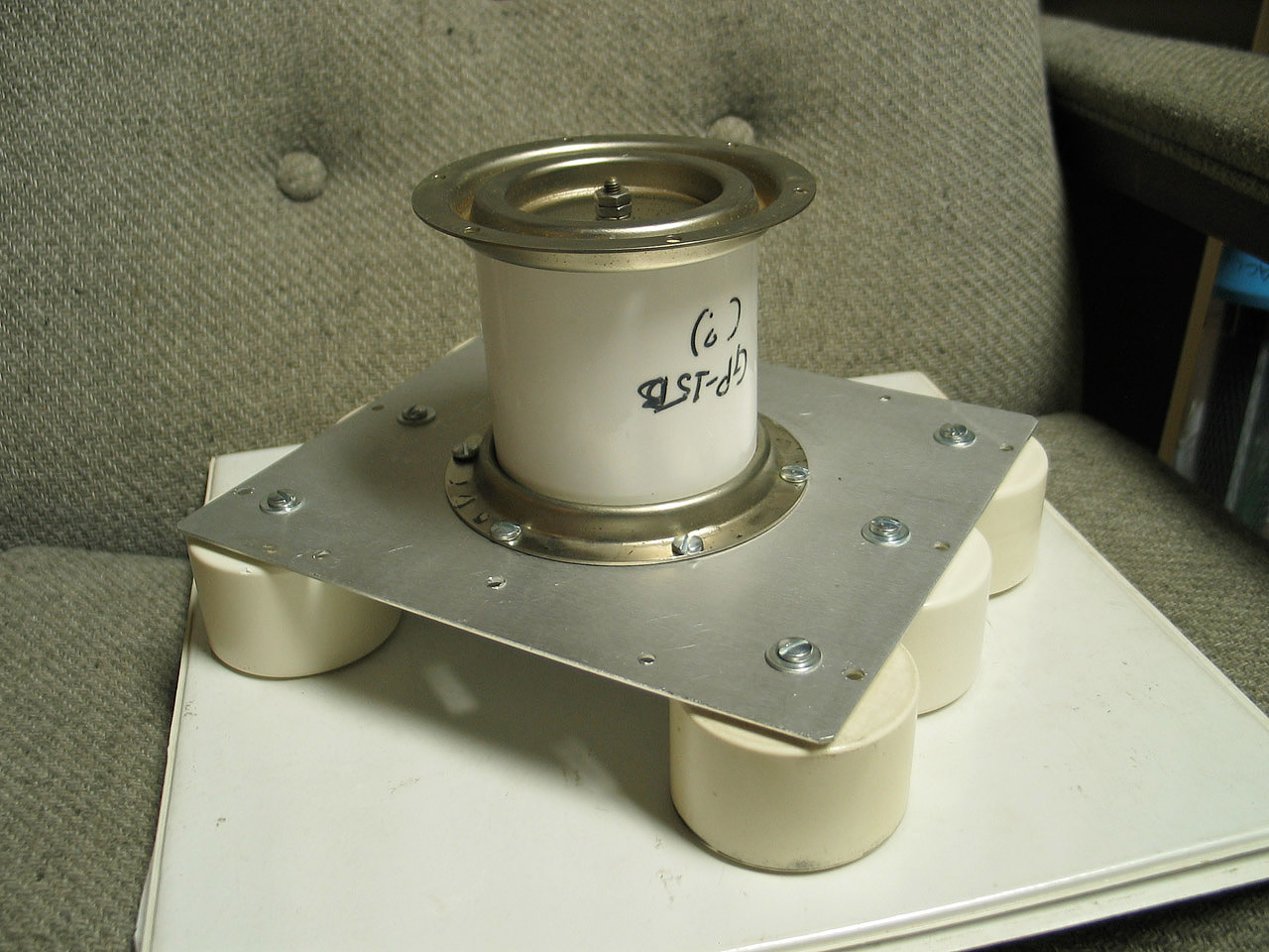
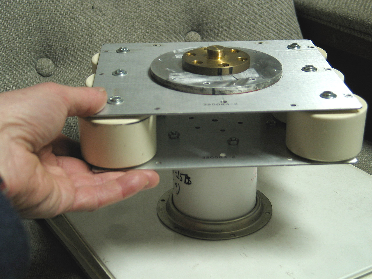
I’ve already shown the baseplate; here’s the rest of
the assembly, as it went together. I’ve included my
hand in one of them, to give you a sense of scale.
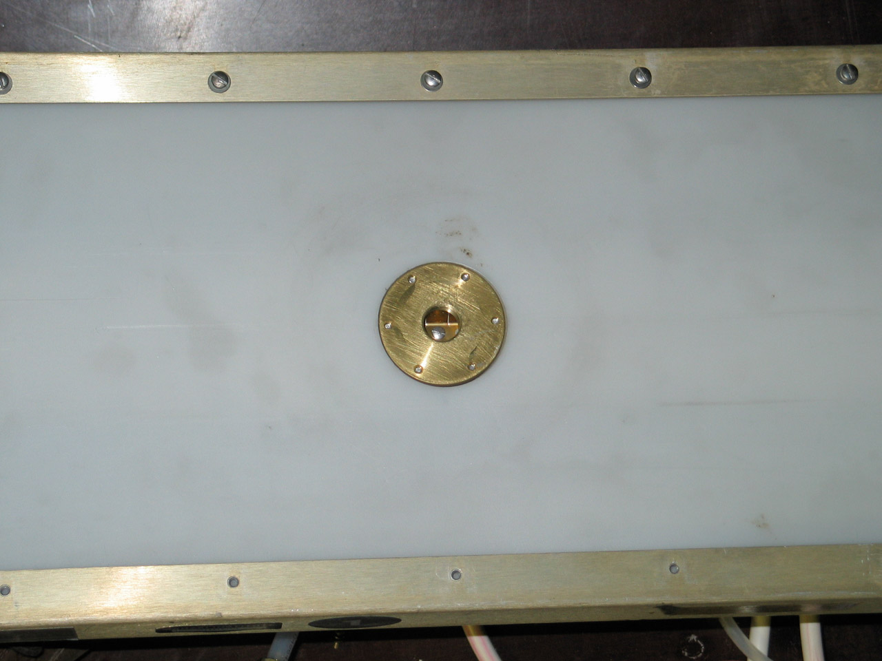
The last of these shows the finished assembly, with
one of its insulating plastic sheets (actually half
a dozen thicknesses) in place. Another sheet goes
under the baseplate (actually at the top in that
photo, because the assembly is upside-down), to keep
it from shorting to the box during firing. More plastic
will go into place during assembly, because a sheet of
copper or brass shim stock will connect the top of the
spark gap to the box, and it passes much too close to
the upper plate of the capacitor bank for comfort at
30,000 volts.
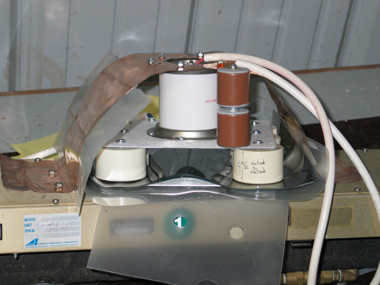
Here it is with everything in place, actually on
the C5000 head:
The two small brown doorknob capacitors standing in front
of the spark gap are there to get it to start quickly when
it triggers. The manufacturer recommends pushing at least
10 amps through it to get it to form a conduction channel;
450 pf at 30 kV should push over a hundred amps, and
should wake it right up.
Before I could try this setup, I had to add some
insulation. Either I didn’t add enough, or there was some
sort of surface spark, because when I raised the voltage
to the highest level I ordinarily use, there was a
flashover. (I was unable to get the spark gap to trigger
at any voltage I was able to reach, unfortunately.)
It’s now too late at night for me to continue working on
anything with 30,000 volts all over it, so I’ve shut the
system down. I’ll go back tomorrow and see what happened
and what I think I should do about it. (One thing I may do
is build a trigger unit that puts out a bit more
voltage. I think my TM-11 boxes are getting old.)
(26 February, 2004)
I now have a homebrew trigger unit that
runs a GP-14 well
at relatively high voltages (the 14 is rated for 12 to 24
kV in air), but not near the bottom of its range. It does
not run the GP-15B yet, but I’m working on improvements,
and I’ll post more to this page as it happens, or to
the next page — I’ve decided to rebuild yet again.
To the top of the LASERs section
Email: it’s the usual “a@b.com”, where
you can replace A by my first name (jon, only 3 letters,
no “h”), and B by joss.
Phone: +1 240 604 4495.
Last modified: Fri Jun 14 23:06:09 EDT 2013
Trouble in the Works
Some Weeks Later...
The Joss Research Institute
19 Main St.
Laurel MD 20707-4303 USA
Contact Information: