This is the first of three (as of late 2004) pages I’ve devoted to this laser. I’ve had a ton of fun getting it running (this page), rebuilding it to replace the main store when that gave up the ghost, and then rebuilding it again during the last few months, to see whether I can get higher output from it.
Note, added 27 December, 2008: I have just rebuilt this laser again, and it is performing extremely well. If you are more interested in performance than history, you can probably just skip ahead to that page.
Photos, this page: With very few exceptions (one of which is the schematic diagram just below), I have uploaded several sizes of each image. If you click one of the bitty ones, get the medium-sized one, and decide that you want something larger, change the ".lg." in the filename to either ".vl." (generally 800x600 px), or ".xl." (generally 1280x960). The exceptions are cropped images, which will typically have ".c1." or something similar in their filenames and won’t be available in the largest size(s), and "portrait"- oriented images, which will be about the same height and thus narrower.
On the other pages I followed a different convention;
On pages 2 and 3, each small image typically goes to a
larger image that is 800 pixels wide or high, depending
on which orientation it’s in. I may indicate that
a larger version is available for some of them. On page
4, almost all of the small images go to larger ones that
are 1280 pixels in their larger dimension. If a large
image is smaller than that, it is a direct crop from the
original, and nothing bigger is available; but in most
cases the original image is available, and you can email
me if you want to see it.
(13 September, 2001)
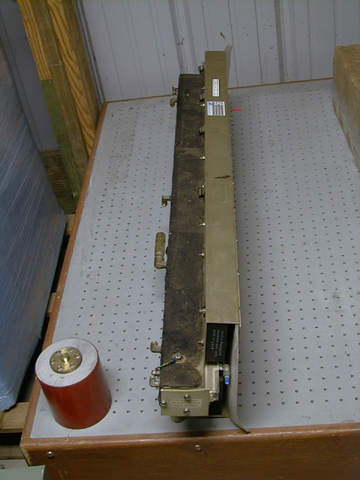
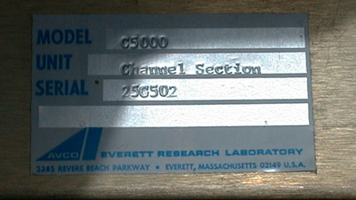
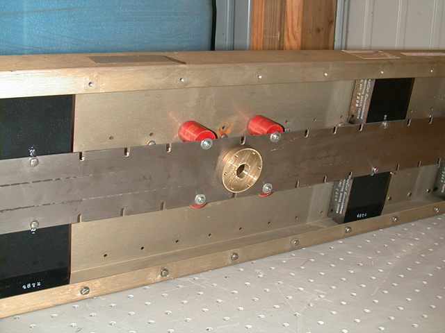
The Institute recently acquired a used C5000 head on eBay. It was described as "the largest nitrogen laser cavity ever built" (it’s 42" long), and the vendor also claimed that it produced 1.2 Megawatts peak power. That should probably be enough, at 337 nm, to create a spark if focused in the open air. I haven’t been able to check this figure yet; if anyone has published spec on this laser or any of its components, PLEASE let me know! (Email address toward the bottom of the page.)
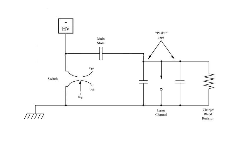
The vendor described this as a "Blumline", which is not only misspelled but totally inaccurate: it’s just a charge-transfer ("dumper-peaker") circuit. I’ve indicated a spark gap as the switch, because that’s what I used; but the laser as it was originally built and configured used a thyratron.
When we received this head, it was missing its switch. (At least the vendor bothered to specify that the switch wasn’t present, so we knew what we were getting into.) Fortunately, we have viable switches.
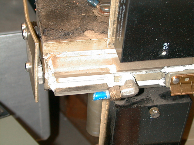
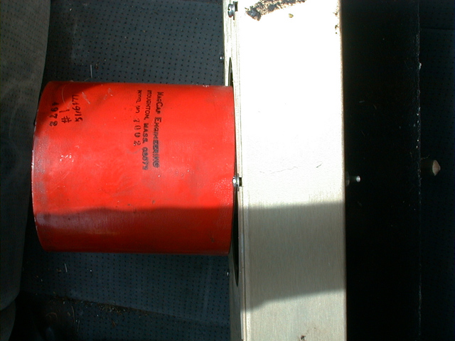
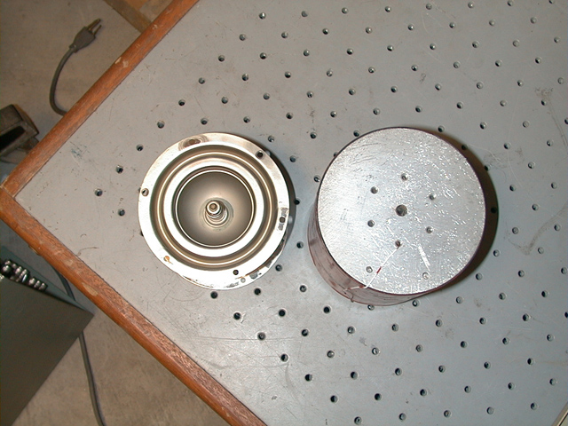
The dumper cap, which measures 12.75 nf on Dave McGuire’s meter (thanks!), is the orange cylinder in the lower left corner of the first photo:
We soon discovered why the device was surplused: it had been dropped on its head. The impact smashed the high-ref mirror by bending its mount, and wanked the dumper-cap mount out of alignment:
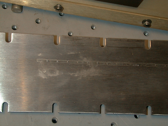
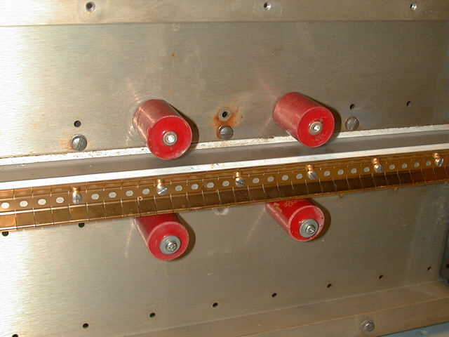
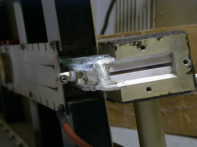
When I took the bottom off the case, the damage to the distribution electrode was obvious (lefthand photo); and when I yanked the electrode, it became clear that two of the peaker caps are damaged (the damage is easier to see on the lower cap in the righthand photo, which is beyond repair):
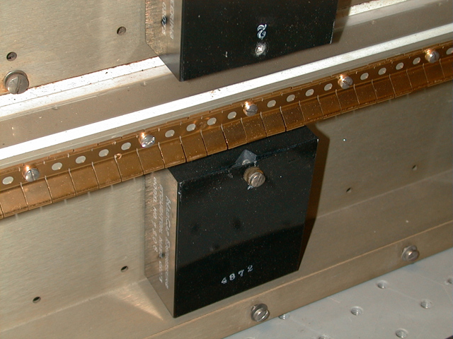
(Note the phosphor-bronze spring-finger stuff that carries current from the distribution electrode to the channel. I can’t believe they did that, but there it is. It seems to work -- shows only moderate damage, and my guess is that this laser made a great many pulses while it was in service during its first lifetime.)
Perhaps worse, one of the sidewalls is cracked (center of photo, just below the peaker cap):
After thinking about this for a while, I’ve concluded that
there’s a large chance this head was retrieved from a
dumpster. (Harrumpfh!)
It’s going to be annoying to repair all of this. I strongly
suspect that the cap mfr no longer exists, and they didn’t
even have the minimal courtesy to indicate the capacitance
or rated voltage on the caps. Fat lot of good a model number
is going to do me now! (Recall that the dumper is 12.75 nf;
that’s a handy size, and argues that the peakers, of which
there are 10, almost certainly rate no more than 1 nf each,
possibly only about half that. This presumes, of course,
that the dumper is intact, and is not, for example, a 40 nf
device with a serious problem.)
(14 September, 2001, revision)
I suspect that my first line of defense, once I’ve tested the dumper cap to make sure that it will withstand 15 kV or so, will be to replace the two dead peakers with blocks of plastic that have 900-pf doorknob caps in them. (I measured the peaker that was damaged but not destroyed, and it tested at 920 pf, suggesting that the peakers are 900 or 1000 pf, in either case +/- 10%.) Then I’ll put a gentle vacuum on the channel and epoxy a piece of glass over the crack to stabilize it. (Even if it leaks a tiny bit, that’s not a problem: up to about 0.5% oxygen in the mix apparently helps.)
I also have to build a gas mixer, but I already knew I was
going to need one for my other lasers, so I have all or
nearly all of the parts already.
(14 September, 2001, early AM)
I have now measured one of the peakers; it is an inch and a quarter thick, and two and three quarters inches wide. The length is not particularly significant, as you can see from the photo -- the distribution electrode is only a couple inches wide. My current concern is the fact that doorknob caps are mostly more than an inch and a quarter tall, but We Shall See What We Shall See, as my old man useta say. I bet I can deal.
(Later, that same day)
I straightened the distribution electrode well enough for folk music. It shows considerable signs of wear on the outside, indicating that they ran it for many many pulses and then flipped it; there is only modest wear on what is now the inside:
I looked at our stock of doorknobs, and discovered that the 900-pf ones were uniformly too tall. (Too bad, -- they are intended for laser use, so they have broad low-inductance terminations and are faster than ordinary doorknobs.) Fortunately, a Sprague 30DKT5, though it’s an ordinary cheapo non-laser doorknob with narrow terminations, is just about the same height as the peaker caps that are in the C5000. We win. I need 4 of them, because they are 500 pf rather than 900 or 1000, but the design of the head is such that there are lots of holes in the particular region of interest. Almost makes me think that they tried various different cap configurations before they settled on the one they used in our unit. Here’s what the rebuild looks like --
The next real issue is the fact that our switches are clearly different from theirs.
[NOTE, added in proof, 19 January, 2004: Dale Nassar has acquired one of these lasers, nearly complete, and he reports that the original switch was, indeed, a thyratron.]
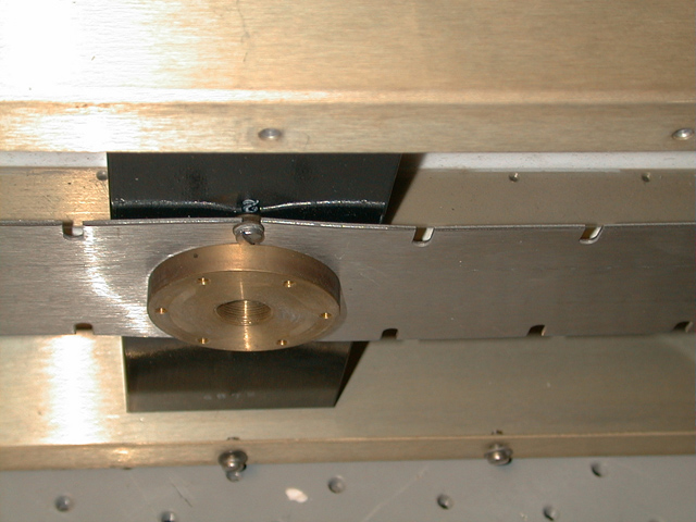
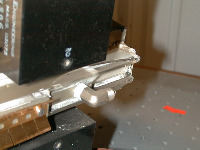
The mounting holes on the back end of the dumper cap are in a rather tight hexagon, and I need to make an adapter so I can jack a GP-14B spark gap onto the thing:
This is not a huge deal, just a piece of brass, but it has to be about a quarter of an inch thick so I can put tapped holes into it. This laser is not likely to be in operating condition tomorrow, but it begins to look like it won’t be too awful long.
(30 September, 2001)
See update, below. Things may have streamlined themselves
slightly.
(15 September, 2001)
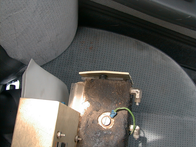
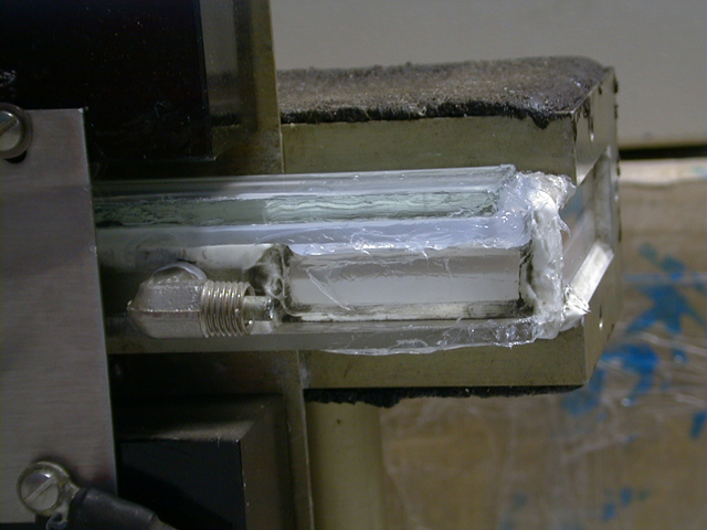
This morning I went to Laurel Glass and Mirror, and asked them for a piece of glass an inch wide by four inches long and 3/16 of an inch (about 4.75 mm) thick. It seemed as though nobody had ever inquired after such a thing before, but they were happy enough to cut it for me. The guy who cut the piece suggested that silicone rubber would be easier to deal with than epoxy, and he was obviously right, so I trundled happily off to the lab and put it on that way, using aquarium caulk.
(The repair is the greenish piece that sits on top of the clear glass in these photos. In the first photo, it extends back underneath the black peaker cap. The translucent glop on it is the silicone rubber, which should be fully set by some time Monday.)
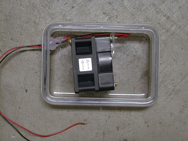
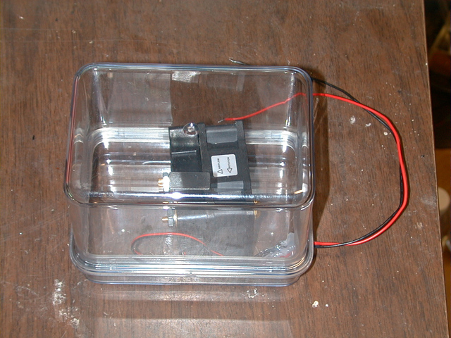
I also started to build the gas mixer. Luck was once again with me: I found that two of my 12VDC fans rotate in opposite directions, which is exactly what I’d hoped for, so I bolted them together, paralleled the wires, and used the same RTV ("Room Temperature Vulcanizing Silicone Rubber") to secure them into the lid of the plastic box that will be the gas mixer when this is all ready to roll. The wires are caulked into a hole I drilled in the lid of the box:
I’ve begun to discuss positioning of the gas bottles with
Chris Daniel. If I can stay reasonably on track, the laser
will emit its first light within a week. (I know, I
shouldn’t even say that, because Murphy awaits behind
every corner. We’ll just have to see how it goes.)
(30 September, 2001)
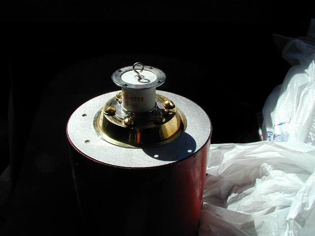
The GP-20B that we bought on eBay arrived, and it is smaller than I thought it would be. I compared it with the hexagon of mounting holes on the back of the capacitor, and it just fits inside them.
It occurred to me that I might be able to find a piece of brass of approximately the right dimensions, so I went off to one of the local thrifts (my other usual thrift having had its top slapped about rather nastily by the recent tornado, it is hors de combat) and found, for a whopping 90 cents, the following object:
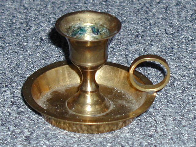
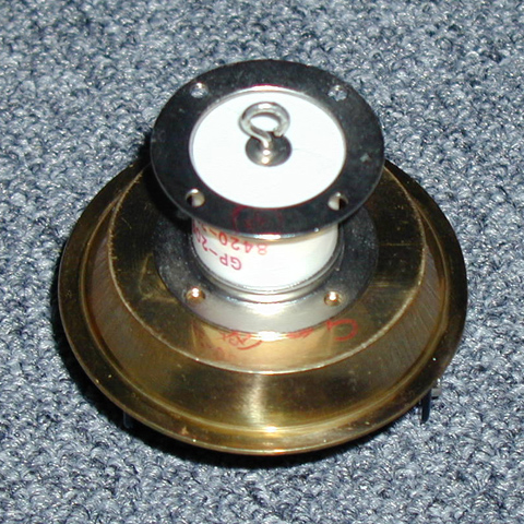
This proved to be two pieces, as I hoped it would, and looks to be fairly suitable, provide I can remove the ring and hammer the bent region of the rim flat. (The candleholder part unscrews, and I’ve removed it.) Here ’tis upside down with the GP-20B spark gap sitting on it:
Unfortunately, my first attempt to remove the finger-ring
failed, and I’m beginning to wonder whether this thing is
actually brass, or maybe brass-plated steel. I will give
it another whirl soon and We Shall See.
(06 October, 2001)
I’ve made various progress. Though each item is fairly small, they do add up --
I still need to put the dumper back on the head, close the head up, cut a piece of shim stock to go from the top of the GP-20B to the case, and find vacuum gauges so I can tell when the channel is at approximately the correct pressure. After that, however, it won’t be long before we push the "Go" button and try this thing.
(I can probably run it temporarily without gauges -- if the
pressure is even reasonably close to optimal, it will lase
unless there’s something else seriously wrong with it.)
(26 October, 2001)
I built a little forest of polyethylene tubing and fittings, running from the shutoff valve at the regulator, on the nitrogen cylinder, to a needle-valve and a little manifold by the laser (it has 3 inlets for nitrogen), with a little crummy gauge that I’ll eventually replace with a real one that reads in Torr. There’s another tubing run from the outlet to the vacuum pump, with another needle-valve and another crummy gauge.
This leaked when I first got it built. I tried using a dry-vane pump, but couldn’t get enough vacuum, so I switched to a refrigerator compressor. After I fixed a few small leaks that were easy to find, I got to the point where I could pull just barely enough vacuum to get a discharge from time to time if I put about 10 kV directly on the peaker caps with my power supply. Of course, it didn’t lase that way. Unfortunately, the dumper cap is just about the same size as the peakers, so if I charge it up to 10 kV and trigger the switch, the result is basically 5 kV on both sides, not enough to cross the channel. Sigh.
At that point I brought over our Alcatel (a real roughing pump). That’s how I found the last few leaks: the Alcatel should not make a burbling noise if it is pulling against a system that doesn’t have any holes in it. There is still a bit of looseness, however, and I couldn’t obtain lasing with the switch operating within its rated range. I got the occasional discharge in the channel, but it was localized.
I finally resorted to running the GP-20B up to the point where it arcs over without any trigger. This is supposed to happen at 14 kV, but I think it’s actually going a bit higher. It isn’t all that great for the gap, and it gives a fairly lousy risetime, but it mostly works. In any case, as soon as I did that, the device made the expectable fluorescent stripes on the piece of bond paper I was using as a target. It is, very clearly, a laser.
Mind you, it’s not working at all well yet. I need to find and excise more leaks; I need to put a mirror on the end that faces out into the room (it’s currently blocked, for safety); I need to put a larger switch on; and I need to swap out the power supply. The one I have on there is very sweet, but it has fixed polarity, and it is negative ground. This means (if you refer back to the circuit diagram above) that I am running the channel in reversed polarity, with the positive side of the supply connected to the place where the diagram indicates "-". I’m sure this doesn’t improve the efficiency. Ahem. Still, we’re pretty ripping pleased.
I’ve actually constructed a high-ref mirror & mount, and when the RTV bathtub caulk has set, some time tomorrow, I’ll put it on. Aligning it may be a bit odd, but I’ll figure out a way. I’ve aligned much worse things in the past. Just by the bye, I about fell over laughing when I removed the original flat piece of aluminum with the high-ref mirror on it. (Well, the bent piece of aluminum with the remains of the high-ref mirror on it, if you want the truth. This piece took a lot of damage, as you can see from the photos above.) It seems that the compliance in the mount was provided by pairs of ancient rubber grommets. We here at The Joss Institute are not so unsophisticated as that, no-sirree-Bob. The compliance in our mount is provided by pairs of nice new faucet washers, separated by little neoprene O-rings.
More (and more photos) as I get the chance.
(2001 October 29)
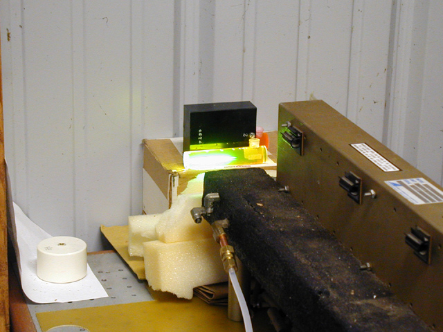
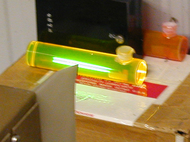
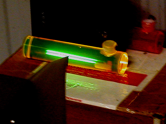
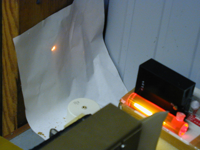
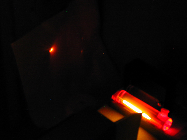
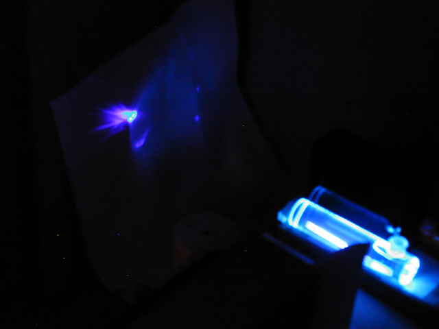
As of today, the unfocused output of the laser easily thresholds Rhodamine 6G or Fluorescein. I don’t actually have any photos showing dye laser output, but I do have a picture or two of the lit stripes on the Fluorescein where the beams from the nitrogen laser are hitting it. These are usually too bright to make out even when the dye isn’t lasing (see the first photo), but I detuned the C5000 by letting too much gas in, and got a photo where you can actually see the stripes if you look carefully. (Middle and right photos.) The one on the right is the good one -- I’ve darkened it to make it easier to see, and the link is to a 640 x 480 version.
Sorry the close-up is blurry, btw -- it’s hard to hold the camera with one hand while pushing the trigger button with the other. The stripes, of course, are quite sharp -- they were only present for perhaps 20 nsec, allowing for the fluorescence lifetime of the Fluorescein.
Here are some relevant photos of the changes I made in the switch section. First, the GP-20B on its adapter, attached to the dumper cap. Next, what that looked like in place on the laser (you can’t actually see much, because it’s hiding inside the bubble-wrap, which is keeping the copper shim stock from arcing over to the hot side of the dumper cap). This photo also shows the 15 kV power supply and the trigger generator.
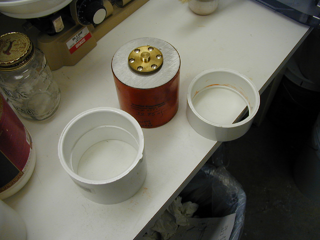
I knew that when I put the GP-14 onto the dumper cap and connected it to a 20 kV power supply, I needed to insulate the hot end of the cap from the copper shim stock with something better than just bubble-wrap, so I went to the local Home Depot and looked around. Sure enough, a butt-splice for 4" PVC pipe just exactly fits around the cap, so I bought two of them. (That’s the peaker end of the big dumper cap that you see in this photo, btw.)
I needed to shorten one of the PVC pieces to fit the peaker end of the cap, so I hacksawed off an appropriate ring and cleaned up the cut end a bit on Chris Daniel’s lathe, by his kind permission.
Not too shabby, for a total of less than 5 bucks, eh? Here’s a view of the assembly, with the GP-14 and the shortened insulator in place (but not the long one):
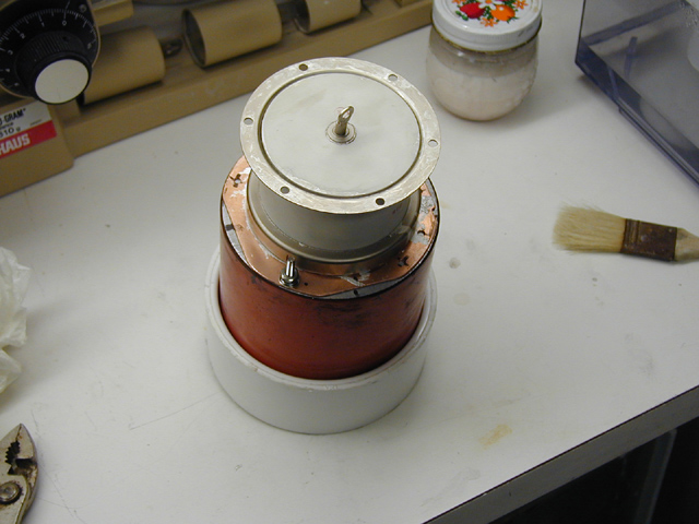
Here’s what it looked like after I put it together and put the new copper shim on it. You can see that I’ve got stiff steel straps holding the shim in contact with the lid of the laser. That should reduce the inductance (and resistance) a little, which may help increase the output power.
I haven’t replaced the broken mirror yet, and I haven’t bothered to check its alignment -- plenty of time for that after I put a new one on there. Tomorrow I’ll construct the new mount and glue a piece of front-surface stuff to it, and I will try to get at least one photo that shows the dye lasing. It probably won’t be very impressive, but it’s neat to see.
(2001 October 30)
I’ve built a new mount & cut a new piece of mirror; hope to install it tomorrow. In the meanwhile, here are some photos of dye cells lasing. The first two photos are (of course) Rhodamine 6G; the third is 7-diethylamino-4-methyl-coumarin. Both dyes are dissolved in 91% isopropanol.
(It is rather difficult to catch the action with the
room lights on, and I never did get a shot of the
coumarin cell lasing that way. Took me dozens of
attempts before I got the R6G lasing with the lights
on.)
(2001 November 26)
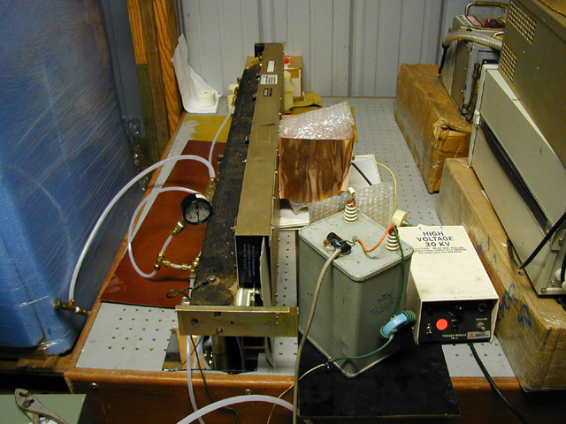
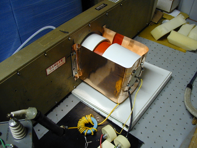
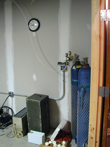
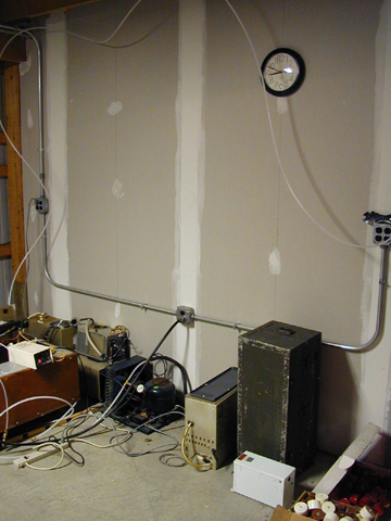
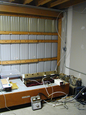
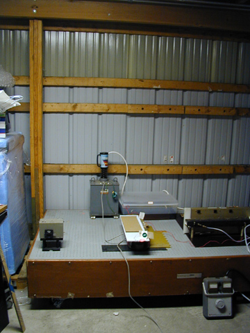
I helped Doug clear a lot of working volume in the lab today. Here are some of the results, starting at the right edge, by the door, and working counterclockwise around the right half of the room:
(I won’t show you the left half of the room because we didn’t get that far, and because we don’t have enough shelving in place yet. We’ll get there later.)
As you can see in the third picture, the laser is now somewhat easier to operate and to point at selected targets. The big Variac controls the voltage of the HV supply, which is behind the laser and to the left of it. We’ll switch to a smaller Variac when we get a chance -- the supply is only 500 watts, and doesn’t need anything quite so chunky.
The supply itself is easiest to see in a larger version of the fourth photo (try the "vl" or "xl" size if you are actually interested). I have protected the output terminal of the HV transformer (let’s hear it for thrifts -- the Advanced Technology HV Transformer "Don’t Sit On Me" Output Terminal Protector and Birdbath cost me 50 cents), and I’ve now got two of the rectifier stacks in series in 2 gallons of Pennzoil in the plastic tub. Well, it was two gallons; it’s slightly less now, argh. (Yesterday there was only one rectifier stack in the tub... I washed my hands several times, but the stuff really doesn’t want to come off.)
I still don’t have a photo of Blancophor FB lasing, but Doug has seen it both at and well over threshold, and was quite satisfied. So was I -- it’s really violet, it’s really pretty, and it’s really bright. I’ll try to nab a photo when I get a chance.
I returned to the lab this evening and replaced the GP-14 with a GP-15. I’m afraid I cut the copper shim just a bit short, and I can’t put the extra insulator in. I need it -- the GP-15 is almost an inch taller than the GP-14, which means that there is a large expanse of copper a little too close to the base of the switch... I’ve had two flashovers, extremely disconcerting. (If you’ve ever heard Doug say, "An Earth-Shattering Kaboom!", please imagine that. Fairly appropriate, though the sound actually wasn’t quite that loud.) I may go with some thin Mylar sheets, or I may recut the shim stock. Either way, the laser does work with the GP-15 in it.
In the process of moving some of the stuff around the lab,
we found a nice little Oriel monochromator. It is at the
left front in the fourth photo. Needs an output slit, but
we should be able to arrange that. Very sweet little device,
with four or five input slitwidths, dial-selectable; also
what will be (when we get the output slit correctly lined
up) dial-in wavelength.
(2002.02.27)
I’ve rebuilt the HV power supply a couple times, and it now has no fewer than ten 15-kV diodes in it, with a 5-Meg resistor between the transformer and the rectifier, and a T-section filter (choke, cap to ground, choke) in the line between the power supply and the laser.
The other day I was running the laser, trying once again to get a mixture of dyes to lase (more about this when I figure out why it sometimes works and sometimes doesn’t), when the dumper cap went "TIK."
Uh-oh.
A little while later it went "TIK" again, and that was that. It no longer does what it needs to do. Sigh...
I knew this was coming. When I reassembled the laser and put the GP-14 on it, the back plate of the cap was clearly loose, and my conjecture is that when the head was dropped, the switch tore loose the end of the cap. Presumably the switch was destroyed at that time, which is why it wasn’t present when we received the head. This is all rather sad, but I can’t say I wasn’t prepared for it.
My current thought is to replace the cap with six or eight
doorknobs, each rated 2700 pf at 40 kV. That would give me
slightly more capacitance and energy than the original
dumper had, and probably wouldn’t be too horrendously
slow. (Hey, if it doesn’t work well, we know what to do:
wait for a smallish Maxwell with stripline connections to
appear on eBay, right?)
Please see
the next page for a record of that effort, or
the third page for more recent work on this laser.
To the top of the LASERs section
Email: a@b.com, where you can replace the “a” with my first name (just jon, only 3 letters, no “h”), and the “b” with joss.
Phone: +1 240 604 4495.
Last modified: Tue May 9 12:14:38 EDT 2017