(07 July, 2004)
As I say on the previous page, it has been some time since I worked on this laser. We acquired a room-pressure nitrogen laser on eBay, and I was busy with that for a while; then we acquired a Questek excimer laser, and I’ve been fussing with that, as well. (It is being a real pig, and I have been unable to find any documentation on it.)
Lately I’ve been thinking about low-pressure nitrogen lasers, though, and as part of that project set I’ve decided to rebuild the C5000 head again. This time I expect to use Barium Titanate “doorknob” caps in the peaker section, which means it will have somewhat higher capacitance than it did in previous incarnations; I am also thinking about using a 30-nf Maxwell for the dumper / main store. This is still in flux, and I haven’t yet decided whether to use a spark gap or a thyratron as the switch this time. I think, though, that I will put the cap on the distribution bus and the switch outboard. (This will make my life easier, especially if I end up using a thyratron.) I’m seriously thinking about limiting the voltage to 20 kV, but that isn’t set in stone yet.
My rationale for the increased capacitance comes from several journal articles I’ve read recently. It is clear that the reason why most amateur nitrogen lasers produce pulses only about 6 nsec long is that they run out of "oomph" -- long before the laser would shut off because of lower-level bottlenecking, the average electron temperature drops to a value that is below what it takes to pump the laser. In fact, if you read enough papers you’ll find that most high-output nitrogen lasers put out pulses up to about 19 or 20 nsec long even without the addition of SF6 or other “helper” gases to the fill.
Here’s the topology I used for this rebuild:
(I haven’t shown the chokes in the + and - HV lines, which
keep the EMP from destroying the power supply and also
mitigate, at least to some extent, the effect of shorting
the power supply every time I fire the switch.)
(late July or early August, 2004)
After some fruitless searching on eBay, I have found some 780-pf 30kV “doorknob” caps. These should fit into the head, and 20 of them will serve as the peaker cap for the laser. One would naïvely think that this would give me 15.6 nf total, but it turns out that things are not so simple. First of all, BaTiO3 caps slowly degrade with age, so the total is likely to be slightly low. Second, because of the way BaTiO3 works, the capacitance actually decreases with applied voltage. (I wish I could find SrTiO3, which does not exhibit this effect... sigh.)
I’m using caps rated for 30 kV, and I hope to charge them to something on the order of 10 kV. (The “dumper” cap will be at 20 kV; but once the discharge starts it’s hard to get the voltage up much higher, so I’ll never reach the theoretical maximum. If I get half of what’s on the main store, I’ll be happy) I’m hoping that I won’t lose too much energy -- I seem to recall that the effect is a lot worse once you get up to at least half the rated voltage of the cap...
(Continuation, 13 September, 2004)
Here’s what the doorknobs looked like, installed, before I put the distribution rail back into the box:
(You can see the rail lying against the interior insulation
sheets, in the back of the photo. The peculiar object in
front of the box, on the floor, is the vacuum regulator. If
that seems slightly counterintuitive, just think of a pressure
regulator that runs into nothingness rather than into the one
atmosphere back-pressure of the air. I suspect that the design
is slightly different, because it has a maximum delivery
pressure of one atmosphere, but otherwise it seems to be
about the same kind of device.)
(13 September, 2004)
The next step is to decide on a main storage capacitor and a switch, and attach them. My initial thought has been to use a Maxwell 30 nf 35 kV cap; we have two of these, and my main reservation about them is that the effective series inductance (ESL) of the design is a bit high -- they are rated at 20 nh, where a really fine pulse capacitor is no higher than 10 nh. ...But even the best caps we have here are at 10 nh, most of the pulse caps we have are 15, and frankly 20 nh just isn’t that much worse, especially after you take the rest of the circuit into account.
As to switching, at least initially I think I’m going to use a GP-70 spark gap. I’ve tested one of these, and it works fine with our old TM-11 trigger unit; it’s rated for use at up to 20 kV in air; and it’s compact. Can’t ask much more than that.
There is then the issue of connecting all these things
together while minimizing the added inductance. I’m still
thinking about configurations to accomplish this...
(11 October, 2004)
I decided on what I hoped would be a viable configuration
(see photos, below, and topology, near the top of the page),
and constructed it. When I attempted to run the laser,
however I got very lousy operation. I did, sometimes, see a
certain amount of very weak lasing, but it was diffuse, and
I saw odd little pink sparks at the end window, which I
thought might indicate a bit of leakage. Barring that, I
thought perhaps the main storage cap might be too big or too
slow. (When I wrote that, I hadn’t brought the laser up to
the full 20 kV yet, and it was clear that higher voltage
might be necessary for proper operation, so I decided to go
ahead and try it.)
Sure enough -- I just ran the voltage up to 20 kV or so, and
the laser works. There’s something very strange about the
gas pressure adjustment, but when I have that set correctly
the output does pump R6G in one of our little fused silica
cuvettes. We are back on the air.
(14 October, 2004)
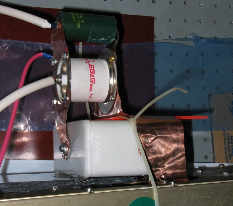
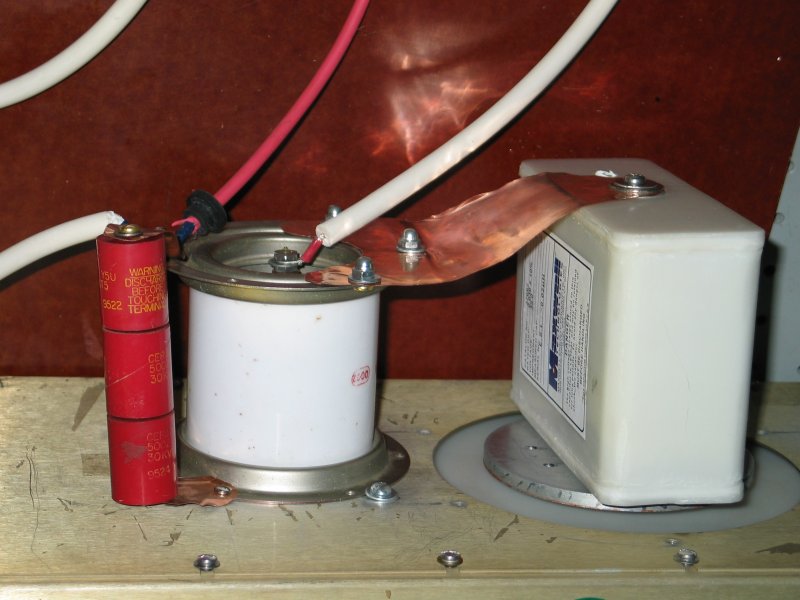
Here are some photos of the “hot” section, showing the way
I connected the main store and the switch. It’s a bit rustic,
I’m afraid, but it does work.
I’ve made a folded or zigzag configuration, with the
“bottom” of the main storage capacitor actually sitting
over the connector at the middle of the cathode rail, and
the triggered end of the spark gap [referred to in EG&G
literature as the “adjacent” electrode] is connected to
the “top” of the main store, over at the left in the
photos, and also to the positive side of the power
supply. The other [“opposite”] electrode of the spark gap
is back near the middle of the housing, where it connects
to a strap that distributes current fairly symmetrically
to the enclosure, which is also connected to the anode.
The heavy white lines go to the TM-11 trigger unit;
the smaller red line is + HV from a 20 kV 5 mA power
supply that I acquired many years ago, surplus. It’s
a rather anonymous gray can with two insulators for
the HV and two smaller insulators for the power line
sticking out the top, and it is not regulated, so I
have no qualms about running it from a variable
autotransformer.
The two green “doorknob” caps outboard of the spark gap
are there to push some current through it as soon as
possible after the trigger pulse arrives; this helps the
gap close smoothly and swiftly, which should reduce the
jitter a wee bit, and should improve the performance of
the laser significantly. I think EG&G used to recommend at
least 10 amps, and I think that 250 pf at 20 kV should
push several times that; but it would be nice to be sure,
so perhaps it’s time for a bit of BotEC (“Back of the
Envelope Calculation”, which should probably also be known
as TCN, or “Table-Cloth Notation”).
If we presume that the risetime is on the order of 2
sqrt(LC), where the total L is perhaps 25 nh [I’m guessing
15 nh for the spark gap and 10 nh for the little caps], that
gives us about 5 nsec; if we then pretend that we’re going
to dissipate the total stored energy of the 250 pf cap [a
whopping 50 mJ] in double the risetime, or 10 nsec, which is
close enough for TCN, we get an average power of 5 MW. I’m
going to guess that we reach the peak power [roughly 7 MW]
when the voltage is still up at about 14 kV, which provides
500 amperes if my head still works right. (If the voltage is
lower we get more current at the same power, so I’m not
going to worry about that.) Even if I’ve dropped an order of
magnitude someplace we’ve still got 50 amps, so I think
we’re okay. (Hey, the device lases, right?)
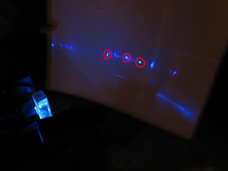
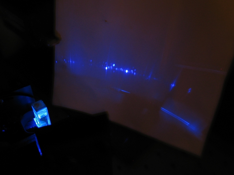
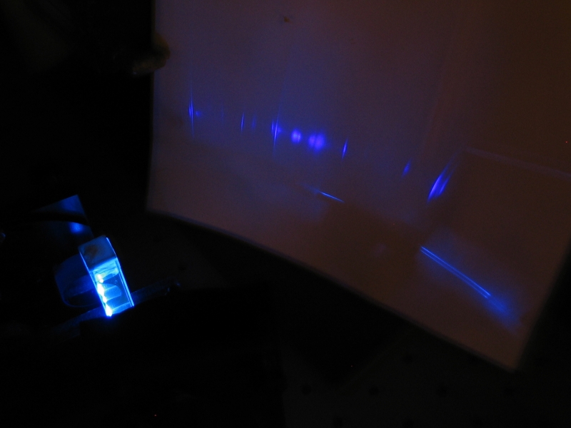
Here are a few photos of early tuning results:
As usual, a bit hard to see; but there’s some greenishness
in the photo on the left (I’ve circled three examples in the
800x600 version), and some violet in the one on the right.
The middle one should be mid-blue. (There are some things
that digital cameras are really good at; this doesn’t seem
to be one of them. Sigh.)
(14 October, 2004)
Ahem. I tried turning on the good old Tektronix 7904
oscilloscope, only to find that it is abysmally and
thoroughly dead -- not a damn thing happened when I
flipped the switch. (My own 7904 mainframe is dead, but
at least it clicks a relay and lights its panel lights a
few times before it rolls over and puts its feet in the
air. Sigh.)
[Note, added in midstream, 16 October, 2004]
It occurred to me that I’d been thinking incorrectly
about the variable autotransformer that I’m using to
control the power supply voltage, and that I was only
putting 18 kV on the laser rather than 20. Sure enough,
the autotransformer has two output settings, and I was
using the 120V setting rather than the more usual
140V one, with the knob at 90%. I’ve pushed it to
100%, so I now have the laser at 20 kV, and the output
is noticeably higher than it was.
[Back on track...]
I’ve just won a 7904 manual on eBay, so I should be able to
get at least one of the scopes fixed. In the meanwhile, I
can get enough of a trace on my own old 7904 frame to do a
rough energy measurement, and it looks like I’m getting a
wee bit over 0.6 mj/pulse. (That is, it took between 155 and
160 mV into the 39.2 ohm calibration resistance in the
sensor head to bring the output of the instrumentation
amplifier up to the same level I got from 50 laser pulses
at 1 pps.)
There is a small chance that I’m not getting the entire beam
to hit the active region of the sensor, in which case the
energy is higher.
Whether I can trust this measurement is another question.
When I checked my two laser pointers, I got the following
results:
Well, hmmm. Not very encouraging. I may have to do
some tweaking, or run the nitrogen laser at higher
voltage. Fortunately I’d misremembered, and the GP-70
will run in air at up to 24 kV, so I can just connect
the laser to our larger power supply and bump it up.
I should be able to do that later today (18 October),
and I’ll report results then.
(19 October, 2004)
I ran the laser from the larger supply, and brought it
to 24-25 kV. That gave me about 0.66 mJ/pulse, which
seemed very low, so I’m going to be looking into this.
One possible factor: this laser has channel width of
about 4 cm. Going by published values, the optimum
E/p for the nitrogen laser is about 80 V/Torr*cm; if
I guess (for convenience) that I’m putting 8 kV on
the “peaker” caps, this gives an optimum nitrogen
pressure of ~25 Torr, rather low. I should be able
to achieve 25 Torr with the vacuum regulator I’m
using. OTOH, it begins to appear to me that I get
best operation at even lower pressure, which argues
that the channel may be starting to conduct when
the peaker voltage is even lower. That, in turn,
tends to argue for relatively slow charging of the
peaker by the dumper, which is seriously annoying.
I’m thinking about changing to a smaller main store,
and also about whether I can/should run this device
at higher voltage. I’ve had trouble triggering the
GP-15B spark gaps, though, at 30-35 kV, and I’m not
really anxious to put a thyratron on this head right
now.
(20 October, 2004, “Later That Same Evening”)
I have now put my old GP-15B on this laser, and
after a bit of fussing with isolating the trigger
unit, I’m getting operation at 25 kV and a little
higher. I think I’m going to have to rebuild the
strap that connects the “opposite” end of the
spark gap to the case of the laser, but that’s
fairly easy. Triggering is a bit unstable, but I
can live with it. The one thing that makes me a
bit uneasy is that it still appears to produce
best output at the lowest pressure I can give it.
There is something wrong about that.
I’m thinking about whether there’s a way to
get a pulsewidth measurement with the ’scope outta
whack. (I can’t get the entire trace on the
screen, and of course the part that’s missing is
at the beginning, where I’d need to see it.)
Ahhh: it turns out that if I select 10X magnification on
the horizontal amp, the trace can be positioned with its
beginning at the left edge of the screen. It’s
only at 1X that the trace is totally screwed up. I’ll
probably need 10X magnification anyway, so this is
highly acceptable.
I have a photodiode, but it has 5 nsec risetime, which
is not really fast enough for this purpose. Also, there
is so much electrical noise that I’m going to have
to put the photodiode assembly into a little Faraday
cage or find some other way to get it away from the EMP
before I can get a measurement out of it in any case.
(Hey, at least I’m making some progress,
and when I find a really fast diode I should be able to
get some data with it.)
(21 October, 2004)
As long as I’m going to be using a GP-15B on this
laser, I want to rework the geometry to minimize the
possibility of flashover and to minimize the inductance.
To that end, I needed some way to attach the base of the
main storage cap to the cathode rail. Fortunately, I
kept the old main storage cap, which had predrilled hole
patterns at both ends. One of the ends was loose when
we got the laser, and I used it later, after the cap
crashed; but the other end remained in place until a bit
earlier this evening, when I removed it. It now has a
hole roughly in its center, through which a mounting
screw goes into the end of the Maxwell cap.
This leaves the positive end of the cap a few inches out,
pointing straight out from the case. Previously (see
photos, above) the cap was flat against the case, with a
sheet of insulator between them. I already have a small
piece of shim stock that lets me connect the “adjacent”
end of the spark gap [with the trigger connection in the
middle of it] to this end of the cap. Next, I need a
larger piece of shim stock, to connect the
“opposite” end of the spark gap to the case
of the laser. At that point I can resume testing.
(22 October, 2004)
It occurs to me that although it would be grossly asymmetric
I can just stomp the GP-15B down on the case, to one side of
the opening for the main store. I think I will try this on a
contingent basis, as it is very simple and eliminates a lot
of hassle with shim stock.
(Some hours later)
This is, indeed, a simple hookup, and didn’t take too long
to implement.
(photo added, 23 October, 2004) Here’s what it looks like:
The three red caps are 500 pf each, and are the “starter”
for the GP-15B. I wanted something taller than what I had on
the GP-70, as the 15 is a considerably larger object, and I
figured I would get more than enough current with 3 caps in
series. This is a temporary lashup, as I mention above and
as you can see by the screw that has a washer holding on to
the bottom of the spark gap. If I decide the configuration
is a good one (which seems likely), I’ll make it permanent.
(back to 22 October text)
I’m getting best output when there’s no
nitrogen coming from the tank, and the vacuum pump is
pulling even lower than the lowest pressure that the
vacuum regulator can deliver, though, which is quite
unsettling. The one thought I’ve had about this is
that I may be into the pressure regime in which the
strike voltage of the channel is increasing as the
pressure decreases. That could give me higher voltage on
the peaker caps with very low pressure. Also, if I let
the pressure come up even modestly, I start seeing
sparks at the output end of the laser. Maybe I should
ditch the last pair of peakers at each end, to see
whether I can lose the sparks. I also begin to think
that I should go to a smaller main store, perhaps half
the size of the current one or even a bit less. That
would give me a bit faster charging on the peakers.
Unfortunately, the only thing I have in that form factor
is only 6 nF, too small.
(Perhaps an hour later)
I removed the caps at the ends of the channel, leaving
16 of them in place (~12.5 nF or a bit less) and now I
get operation at a slightly wider range of pressures.
Guess that was a good move. I will be looking for a ~16
nF cap to use as a “dumper”, unless I get
tired of waiting and decide to make one out of doorknob
caps I’ve got around. I may just go back to the
base I was using the last time I tried to rework this
machine (see previous page); but that was a tight fit,
so I’ll have to think about it and perhaps modify
it or shim it up.
I’d give you a measure of the output energy, but
I’ve been unable to get one — the little
instrumentation amp that I use to bring up the output of
the sensor is oscillating wildly. I suspect that the
chip was damaged by something, perhaps some sort of
discharge or EMP (ahem). I’ve got at least one
more of these chips, if I can just find it...
On to a page about another commercial nitrogen laser we acquired surplus
On to a page about a commercial TEA nitrogen laser we acquired surplus
On to a pageset about the nitrogen lasers I’m currently designing
and building, as of mid-2005
To the top of the LASERs section
Email: it’s the usual “a@b.com”, where
you can replace A by my first name (jon, only 3 letters,
no “h”), and B by joss.
Phone: +1 240 604 4495.
Last modified: Fri Jun 14 23:07:19 EDT 2013
Step Three: Assembly and Operation
Later, That Same Day
A Few Explanatory Images
Step Four: Measurement and Characterization
1. Pulse Energy:
2. Pulsewidth
Let’s Get This Straight --
The Joss Research Institute
19 Main St.
Laurel MD 20707-4303 USA
Contact Information: