(16 September, 2009: this is a 2006 rewrite and continuing revision of a page I originally wrote in July of 2005.)
I have been rereading some papers on nitrogen and excimer lasers, and rethinking my understanding of the important characteristics of a nitrogen laser. Some of the issues are simple and some are fairly obvious, but some are not so easy to understand. This page attempts to examine and clarify issues pertinent to DIY high-performance nitrogen lasers, and to take a look at what you need to know in order to build one. Follow-on pages examine specific designs and the performance that you can expect to achieve with them.
If you want a high-performance nitrogen laser and you can’t afford to buy one, it is certainly possible to construct one; but even if you start with a good design, there is only a modest chance that you will obtain the specified performance level on your initial attempt. The nitrogen laser is not a high-tech device, but it is sufficiently complex and depends upon the values of enough parameters that there is no substitute for repeated hands-on experience. It is probably a good idea to plan on building your laser three times; if you manage to get it to work well in one or two, you can count yourself either lucky or very accomplished. I will note that over the course of writing this pageset I built four to six lasers (depending on how extensive a rebuild has to be, before you consider it to be a new machine), and I rebuilt almost every one of them at least twice. I needed that experience in addition to what I learned from the articles I read. There is also the plain fact that if you don't buy one and you don't build one and you don't find one and nobody gives you one, you don't have one.
The nitrogen laser was discovered (not invented) in 1963, by H. G. Heard. He published his discovery in Nature. (You can find a proper citation by following the “References” link, below.) Nitrogen was, if I recall correctly, the first convenient pulsed UV laser, and is still a DIY favorite because it is straightforward, easy to construct, and doesn’t involve poisonous or corrosive or horrendously expensive gases. I think that a lot more of us would be building excimer lasers if we could afford the xenon (a large tank of xenon costs many thousands of dollars), or if we were too stupid to be afraid of fluorine, nitrogen trifluoride, and chlorine.
Unfortunately, although nitrogen is cheap and easy to handle, it is not well behaved as a laser. The nitrogen laser has a few undesirable characteristics, the most prominent of which is a problem of lifetimes. When you excite a nitrogen molecule (which we do in our lasers by slamming an electron into it), it can be raised to any of several states. The good news is that it’s easy to get it to go into the particular excited state that forms the upper laser level we want. That state has a lifetime of about 40 nsec at very low pressure, but the lifetime decreases as the pressure goes up, and at 1 atmosphere it is only about 2.5 nsec. (It is important to remember that this is about the partial pressure of nitrogen in the gas mixture; if you have 1 atmosphere total pressure, of which 30 or 40 Torr is nitrogen and the rest is helium, your laser is still a low-pressure nitrogen laser. This turns out to be extremely convenient, and I discuss it below.)
A short upper-level lifetime doesn’t have to be a problem; with dye lasers, for example, it is essentially a non-issue. (The upper-level lifetime of Rhodamine 6G is a little over 4 nsec; but R6G easily lases for a microsecond or more in flashlamp-pumped lasers, and it can even lase CW with appropriate laser pumping.)
The lifetime of the lower laser level, however, is significant; it needs to be shorter than the lifetime of the upper laser level. With organic dyes this is not a problem, but with nitrogen it is: the lifetime of the lower laser level is about 1,000 times as long as the lifetime of the upper level. A laser only operates when there is what is called a “population inversion” — when the number of excited centers (atoms, ions, whatever) in the upper laser level is higher than the number in the lower laser level by a wide enough margin to overcome the losses in the device (and remember, the output counts as one of the losses). An excited center in the lower laser level can and will absorb light at the laser wavelength. True, that puts it in the upper laser level, and it can then re-emit the light; but there is no guarantee that will do so as part of lasing, or even in a useful direction. It certainly doesn’t help, and if there are too many centers in the lower level (anywhere near as many as there are in the upper level, for example), lasing is not possible.
In order to get your nitrogen laser to turn on, you must excite lots of nitrogen molecules into the upper laser level; they fall out of that level, many of them to the lower laser level, most of them (though not all — nothing is 100% efficient) emitting photons in the process, ...and then they sit there. Within a very short time (almost always less than 30 nsec for low-pressure nitrogen lasers, after lasing begins) it becomes impossible to sustain a population inversion, and lasing ceases. It doesn’t matter how strong your discharge is, the gas can’t lase any more. You have to stop and wait for many microseconds while the nitrogen molecules in the lower laser level return to the ground state. This limits the repetition rate of the nitrogen laser, probably to a few kHz.
(The timescales are different for atmospheric pressure nitrogen lasers, which cannot lase for longer than a nanosecond or so, but the principle is essentially the same.)
In addition, cold nitrogen lases better than hot nitrogen, so it helps if you flow the gas through the laser and allow enough time between pulses for cool gas to get in and replace the gas you’ve just heated by running millions of watts of electricity through it.
This issue also limits the repetition rate of a nitrogen laser. If you want full peak power, either you have to flow the gas extremely fast (which wastes gas and costs money), or you simply don’t pulse the laser more than 4 or 5 times a second. If you want maximum average power, on the other hand, you can pulse your laser more frequently, possibly as often as a few hundred times a second if your power supply can sustain that and if you can cool the parts of the system that tend to get hot. (At a few joules of input energy per pulse, a rep rate of 100 Hz takes hundreds of watts, most of which comes out as heat.)
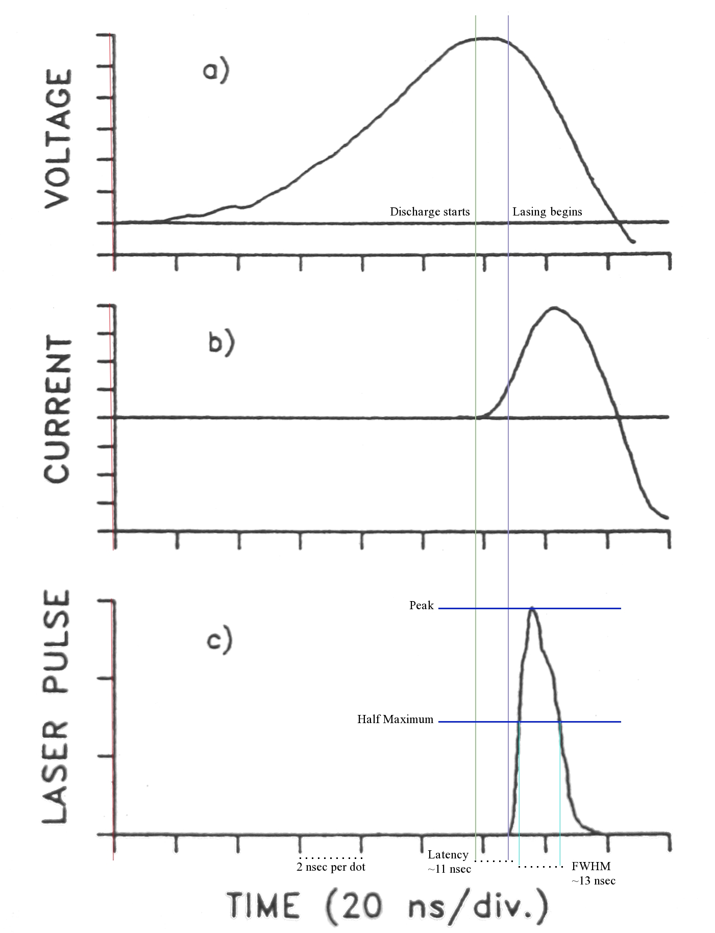
Something we don’t often think about is the fact that lasing does not start “instantly” after current begins to flow in the channel. There is always some latency before enough nitrogen has been excited to create a population inversion. (There’s no such thing as an “instant” in physics or electronics in any case.) Here is a diagram, adapted from one I found in a research paper, showing the voltage, current, and laser output curves of a high-performance charge-transfer laser:
(If you click the diagram, you will get a larger version.)
The latency typically ranges between 10 and 15 nsec; in the example given here, it is about 11 nsec. (Because of the lower level bottleneck problem, it probably can’t be longer than about 30 nsec unless the discharge starts off slowly and then ramps up to maximum power extremely abruptly.) If your driver circuit cannot deliver energy to the discharge rapidly enough, the total energy it delivers doesn’t matter; your laser still won’t reach threshold.
Moreover, because the lifetime of the upper laser level is 30-40 nsec under actual conditions, which means that the laser pulse can easily be 15 or 20 nsec in duration, the driver circuit must deliver considerable voltage (and power) for at least 30 nsec in order for bottlenecking to get a chance to occur. Small lasers, as I mention elsewhere on this page, “run out of steam” long before that point.
Something very few DIYers are aware of: there are at least FOUR nitrogen laser wavelengths. The “usual” nitrogen laser, operating in the second positive system, emits at 337.1 nm in the UV, often at several closely-spaced wavelengths. It is also reported to emit at 357.6 nm in the UV under some conditions, though very few articles mention this.
Then there is an ionized molecular nitrogen laser, which puts out blue light at approximately 428 nm. That laser doesn’t typically operate without mirrors, so very few DIYers have seen it, but Mark Csele mentions it on his excellent site — his students sometimes see it by filling an excimer laser with helium and adding a very small amount of nitrogen.
In addition to these there is an infrared nitrogen laser
that operates in the first positive system, and if you
measure the output of your laser without absorbing IR,
you may get a spurious value. I think the IR
laser and the blue laser only operate in an actual
resonant cavity, which requires two mirrors; but I am
not entirely certain.
While it should be possible to pump nitrogen with a magnetic pulse compressor, a technique that is used in some excimer lasers, pulse compressors are difficult to design and build, so DIYers have not (as far as I’m aware) used them. We typically use capacitive discharge, in one of two main circuit designs. These are “Doubler” circuit (often inaccurately called a “Blumlein”, although it is nothing of the sort), shown in the upper half of the diagram; and the Charge-transfer circuit, shown in the lower half. The cathode of the laser is shown as an arrowhead, and the anode as an open circle.
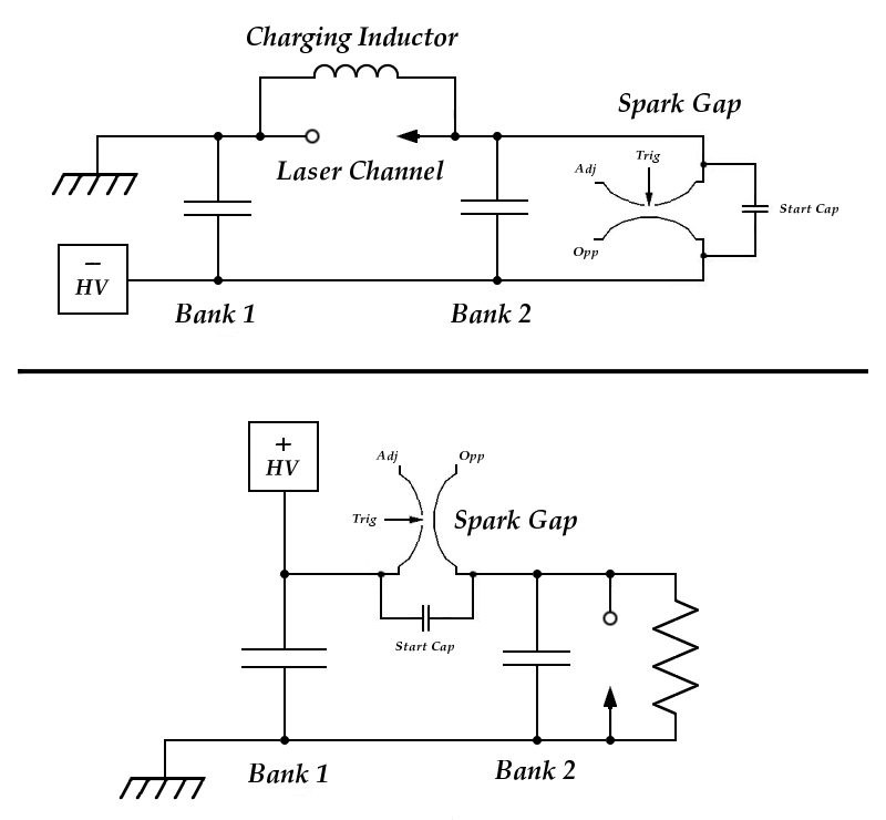
For convenience, I have drawn the voltage-doubler circuit with the negative terminal of the power supply as the “hot” terminal and the positive terminal at Ground [Earth] potential, but this is not crucial. Two things are crucial, though. The first is that during charging the laser channel needs to be grounded [earthed], so that the high voltage does not simply run through the hose to the vacuum pump. Second, it is important to make sure that the spark gap is operated correctly. (This may vary from gap to gap; I happen to have a commercial gap that is specified to operate as shown in this diagram, with a positive-going trigger pulse on the trigger pin, which is adjacent to the positive electrode.)
In addition, I have drawn the doubler circuit with a charging inductor; in practice you can use either an inductor or a resistor. It’s a good idea to try both, and use whichever works better in your machine. (It is also a good idea to put both a choke and a resistor in series with the power supply, because the laser generates a hefty voltage spike when you fire it, and you can damage or destroy your power supply if it is not adequately protected. If your laser is large enough, it also generates an EMP [Electro-Magnetic Pulse] when you fire it, and can damage cameras and other equipment that are too close to it.)
Both capacitors or banks, depending on the design, are charged. (An inductor or resistor permits them to be charged by a single power supply, as is shown in the diagram.) When they are at the desired voltage, the spark gap is triggered.
It takes some nsec for a conduction channel to develop inside the spark gap; this is assisted by the small capacitor (labelled “Start Cap”) across it, which in the case of the commercial gaps I use needs to be just large enough to produce a current of at least 10 Amperes in the gap, as rapidly as possible; a few hundred pf is typically more than enough. Note the fact that this capacitor needs to be able to handle at least the initial charging voltage. It is a good idea to use one that is rated somewhat higher, as it is likely to last longer.
As the switch begins to conduct and current starts to flow through it, the combination of the inherent inductance of the circuitry and the capacitance of Bank 1 produces a resonant (“tank”) circuit. If the laser does not fire, the maximum voltage across the channel will approach twice the initial charging voltage as the tank circuit “rings down”. (If you have a fast enough oscilloscope and a safe way of probing the high voltage that is present on the capacitor, you can use this fact to get a sense of the inductance and resonant frequency of that side of your circuit.)
In normal operation, however, this never happens. At some intermediate voltage the laser channel starts to conduct, and current begins to flow through it. Within some nsec the discharge is well developed, and lasing typically begins about 10 to 15 nsec after the channel starts to conduct. Lasing ceases when the electrons in the discharge no longer have enough energy to excite nitrogen molecules effectively, or when there is enough population in the lower laser level to quench the laser.
(Most small lasers cannot pump long enough for bottlenecking to occur; they terminate by “running out of steam”, typically in less than 10 nsec. A few fairly high-power nitrogen lasers also appear to run out of steam quickly, but they deliver large amounts of energy to the discharge in that time, which results in large output.)
For optimum performance, the two capacitors or capacitor banks should have approximately the same value. (This has been tested by several investigators, with fairly uniform results.) They should also have extremely low inductance. In fact, in DIY terms the inductance of the entire circuit should be as low as is practical. The capacitors should be physically as close to the laser channel as possible, for example, and the connections should be broad foils, rather than wires.
A circuit of this type was published in the Amateur Scientist column in Scientific American in 1970. It was intended for DIY construction, and is a good design that remains popular even today, but the description of its operation was seriously flawed. The author used unreasonable values for parameters like the speed of his spark gap switch, and the resulting explanation did not make sense. Unfortunately, it was unthinkingly accepted and followed by many people, and echoes of it even show up in the scientific literature on nitrogen lasers.
In a Charge-transfer (“CT”) circuit, only Bank 1 is charged directly by the power supply. When it reaches an appropriate voltage, the spark gap is triggered. Within a short time (some nsec), as the gap begins to conduct, Bank 1 (sometimes referred to as the “Dumper”) begins to discharge into Bank 2, charging it. When the voltage across Bank 2 gets high enough, the laser channel starts to conduct, after which both banks push current through the channel. (Several groups have tested this, and it is clear that Bank 1 contributes to lasing, at least to some extent.)
Because Bank 2 (sometimes referred to as the “Peaker”) provides the majority of the drive for the laser, it needs to be as fast as possible, with low self-inductance, and needs to be as close to the channel as is practical, with low-inductance connections. These characteristics are less crucial for Bank 1; but because it also contributes to some extent, faster switching and lower circuit inductance, along with careful choice of capacitors (look for those with low ESL [Effective Series Inductance] ratings), will typically give you more output and higher efficiency.
In a CT circuit the Dumper is generally significantly larger than the Peaker, often by a factor of 2 or 3 and sometimes as much as 4. In some cases it is possible to have a resonant effect here too, which can, in principle, charge Bank 2 to more than the initial charging voltage on Bank 1. However, I wouldn’t count on it.
Doubler circuits are usually more efficient than CT circuits; but because both capacitors are generally left on charge all the time when the laser is in operation, they suffer more from aging effects. In addition, as I’ve already mentioned, if the laser is being operated at less than atmospheric pressure it is necessary to keep the channel at ground potential to prevent the power supply from discharging through the hose to the vacuum pump.
For high-power nitrogen lasers, more workers seem to use
Charge-transfer circuits; but both forms can deliver
output energies of over a dozen millijoules, and both
can produce pulses that are more than 10 nsec long; the
performance level is largely a matter of design and
construction, and the choice is yours. (See, however,
the discussion of transmission lines, below.)
As I already mentioned, most small lasers cannot sustain a population inversion for more than a few nsec. As it happens, there are some high-performance lasers that also put out short pulses; these use resonant effects to deliver their energy to the channel as rapidly as possible.
One way to accomplish this is to construct the capacitors (both banks for the doubler circuit, or the Peaker in the Charge-transfer circuit) as transmission lines. This is nontrivial for several reasons, the most obvious of which is that a transmission line works properly only if it is reasonably well matched to the load that it is driving. Because the effective impedance of the laser channel changes rapidly during the firing cycle, matching it is not fully possible. My understanding, as of this writing, is that at the peak of the electrical pulse the channel of a representative nitrogen laser presents a load of 0.1 to 0.4 ohms to the driving circuit; this is a very approximate value, but will serve for now. It is possible to make a transmission line with a characteristic impedance in the 0.1 to 0.4 ohm range, and such a line should pump a nitrogen laser reasonably well. Even in the best case it will not operate entirely as a transmission line; but to whatever extent it does, the performance of the laser will be improved.
The characteristic impedance of a transmission line is usually given by this formula:
Z0 = (377/sqrt(ε))×(s/W)
ε is the dielectric constant, s is the spacing between the plates, and W is the width of the plates. (Notice that because the formula uses only the ratio between s and W, it doesn’t matter what units they are in, so long as the units are the same for both.)
An example: Let’s say I want to pump a nitrogen laser channel with two transmission lines, one from each side, either as peaker caps or as a voltage-doubler circuit. I have a large piece of circuitboard that I hope to make the lines from.
The dielectric is 2 mm thick, and the board is 32 x 36 inches. (Uh-oh. Already need to make one conversion.) I will be charging the main storage capacitor to about 30,000 Volts, so I need to etch away the copper from roughly the outer inch of board; this gives me either two pieces that are 16 x 30, or two pieces that are 14 x 34. I am going to choose 14 x 34, and use the longer side as the width. 34" is about 86 cm, give or take a bit.
The dielectric constant of ordinary circuitboard is about 5.3, which is convenient because the square root of 5.3 is very close to 2.3. So:
Z0 = (377/2.3)×(.2/86)
This comes out to be about 0.38Ω, which should at least be viable, even if it is not fully optimal. (This depends on the dimensions of the laser channel, the fill pressure, and various other parameters.)
The capacitance of the two lines, btw, totals about 14.3 nf.
Let’s do the same calculation for the Amateur Scientist laser. That laser is constructed from a piece of circuitboard that is 30 x 45 x .04 cm, with 2 cm etched from the margin, and a 5-cm strip removed from the middle of one side to define the capacitor plates. This gives us two capacitor plates, each 18 x 26 cm, and we will consider these to be the transmission lines. It is clear from the article that the 26 cm dimension is the width.
Z0 = (377/2.3)×(.04/26)
This comes out to be just over 0.25Ω, which is
quite good. The capacitance of these two lines totals
about 11 nf.
If you can adequately pump a longer channel it will give you considerably more output, assuming you don’t saturate the gain.
As a thought-experiment, imagine that you have a laser channel with gain of 10X per unit length at a given pumping level. I am going to assume a few things: first, that we are far from saturation; second, that we are well above threshold. (Both of these are reasonable for nitrogen lasers.) Third, that it takes 2 units of pumping energy to bring this laser to threshold; and fourth, that we are putting a total of 24 units of pumping energy into the device.
For convenience, let’s pretend that our laser is being run as an amplifier, with an input pulse of 1 unit of energy. (Not the pump; remember, that’s 24 units.) The laser is 1 length unit long, and it has gain of 10 per length unit, so its output is 10 units of energy. (See “A”, below.) If you put two of these lasers in series, one after the other, you do not get a gain of 20!
A)   1 -> | x10 amplify | -> 10

B)   1 -> | x10 amplify | -> [10] -> | x10 amplify | -> 100
Of course, this cannot be extended indefinitely. At some point you saturate the gain; at that point the increase ceases to be exponential, and becomes merely additive.
If you don’t double the energy input when you double the length, things are not quite as rosy; but if you are operating well above threshold you can still expect some improvement. Let’s take our 24 units of energy input, and spread it over two of these lasers. Each device takes 2 energy units to reach threshold, which leaves 10 energy units for pumping beyond that level. Our original device also took 2 units to reach threshold, but had 22 units of pump left over; if nothing else interferes, this means we should get roughly 10/22 as much gain, or a little over 4.5X per unit length...
A)   1 -> | x10 amplify | -> 10

B)   1 -> | x4.5 amplify | -> [4.5] -> | x4.5 amplify | -> 20.25
Eventually, however, if you make the laser long enough, you start having trouble with bottlenecking in the lower laser level. If you build a nitrogen laser that is 4 meters long and run it at relatively high pressure, most of the “output” will be absorbed in the gas and will never escape from the laser. (It is possible to avoid this problem by using travelling-wave excitation, but that turns out to be rather difficult to accomplish.)
At low partial pressures of nitrogen and reasonable
channel lengths, however, this is not an issue: even a
channel that is more than 1 meter long is entirely
viable, and in fact many high-performance nitrogen
lasers are that large. (Light travels at about
300,000,000 meters per second, so it takes a little over
3 nsec to go 1 meter. If your laser doesn’t
bottleneck for at least 12 nsec, which should certainly
be the case unless the latency is very long, a channel
length of 1 meter is obviously viable. If you are
using special techniques to get a very short pulse,
however, and you are populating the lower laser level
very quickly, 1 m may be too long to work well.
Likewise, if other processes either begin to absorb the
output or disturb the optical path through the gas, you
may have trouble with a long cavity.)
As mentioned, the electrons in the discharge need to have a certain amount of energy in order to be able to pump nitrogen molecules. This energy is usually given in Volts per Torr Centimeter; the parameter is named En or Ep, depending on how it is expressed. The optimal value is about 80, but some researchers seem to find that they get best performance at higher values, often around 100. (It is possible that calculations of this value are not extremely accurate, or that other factors can affect the optimum; I don’t really know for sure.)
For example, if you were pumping nitrogen at 5 Torr pressure, with 3 cm between your electrodes, you would have to push enough current through the discharge to maintain 1200 to 1500 Volts across it; if your capacitors weren’t big enough or your system weren’t fast enough to do this, your laser wouldn’t reach maximum output, and in the worst case it might not even reach threshold.
Achieving 1200 Volts in such a discharge isn’t very hard; but most nitrogen lasers operate at 30 to 120 Torr and at channel spacings anywhere from 1 cm to 4 cm, which means that they need considerably higher voltages. At 60 Torr and 4 cm, you need enough current to sustain about 20 kV or even more if you want to reach the optimum electron energy and get the best possible performance from your laser. If the effective impedance of your channel is 0.2 ohms, you must push 120,000 Amperes through it in order to bring the voltage up as high as 24,000. It takes a very good design (and very good components) to accomplish this.
I once spoke with a nitrogen laser designer at
Avco-Everett Research Lab; he said that anyone can build
a nitrogen laser, that it takes considerable effort to
build one that puts out as much as 250 kW, and that only
someone who is expert at it can build one that puts out
much more than half a Megawatt. As far as I can tell
from my own experience, he was entirely correct. (Please
bear in mind, however, the fact that he was talking
about low-pressure lasers. At the time, around 1971,
there weren’t any commercial atmospheric-pressure
nitrogen lasers. Also, preionization techniques
weren’t as well developed as they are now,
which works in our favor.)
This is closely related to the previous issue, but not identical. If you dump enough current through your channel to sustain the required voltage, you are dissipating energy at a certain rate. It is fairly easy to figure out how much energy you put into the channel and what volume of gas you are pumping. The one tricky bit is whether you count only the energy that goes into the gas up to the point at which lasing ceases, which is not necessarily easy to determine, or whether you count all of the energy that is stored in the capacitors, which is not realistic because much of it is put into the discharge much too late to do any good.
In general, my feel for this is that high-performance nitrogen lasers tend to put at least 30 to 40 joules into the channel per liter of gas that they excite. For example, if the discharge in your channel is about 3 mm thick and 40 mm wide, that represents an area of 1.2 square cm; if the active region is 80 cm long, you are pumping 96 cubic cm of gas. You have to put about 3 joules (or more) into this, in a very brief period, if you expect to get well above threshold.
Let’s look at it a different way: if this laser is operating at 30 Torr, you need to sustain a voltage of about 10 kV across it to be in the general region of the optimum. If the effective impedance is 0.2 ohms, that takes 50,000 Amperes, which is 500 MWE (MegaWatts of Electrical power). If we think of this as the peak power, and use 250 MWE as the average power, and if we allow for 10 nsec startup time followed by 10 nsec lasing time, for total time of 20 nsec, this calls for 5 joules. (At 1 GW you are dissipating 1 joule per nanosecond; at 250 MWE it takes 4 nsec to dissipate 1 joule.) While that is not identical to the figure we got in the previous paragraph, it is certainly close.
The problem, of course, is that this is only the amount
of energy that goes into the discharge up to the point
at which lasing ceases. In the real world, the driving
circuit is still pouring energy into the channel, and
continues to do so for many nsec. The total stored
energy in the capacitors is likely to be more like 25 to
50 joules. It should be clear from this that a nitrogen
laser is not a particularly efficient device. If you put
30 joules in and you get 6 millijoules out (which is
quite respectable; for a 12-nsec pulse it represents
average power of half a million watts), your efficiency
is 0.02%...
If you compare the performance of air and nitrogen, you find that air is a terrible laser. There is typically as much as 10X difference in output power between them. (Note, however, that to the eye, if you use the beam to excite a fluorescent material so you can see it, the difference appears much slighter. This is because your visual response is essentially logarithmic. It has to be: full sunlight is about a million times brighter than moonlight, and if your response weren’t the way it is, you either wouldn’t be able to see in the day, or you wouldn’t be able to see at night.)
The difference is caused by the fact that in large quantities, oxygen poisons the laser. I have seen, however, at least one study in which the authors found that in small quantities, oxygen actually improved their performance. They found the optimum to be about 0.3%; any more than 0.5% was deleterious. Because of this, if you are building a high-performance laser you have to be careful to eliminate leaks in your vacuum system. Air is 20% oxygen; if you operate your laser at 50 Torr, as much as 1 Torr of air is probably beneficial. (1/50 of 20% is 0.4%.) Much more than 1.5 Torr, however, and you are going to see degraded performance. To put that a different way: if you can’t pump your channel down to less than 2 Torr with the inlet valve shut, you need to find and fix some leaks.
Helium, which is readily available, is extremely helpful. If you have sufficient preionization (see the section about that), you can run a low-pressure nitrogen laser at atmospheric pressure, eliminating the need for a vacuum pump, by filling the laser with helium and adding a tiny bit of nitrogen. I have done this myself. It uses up large quantities of gas, and can be expensive, but if you don’t have a vacuum pump and you want to run a low-pressure nitrogen laser, it offers you a chance to do so. It also means that you do not need to be as careful about leaks, though they are still something of an issue.
Even at lower pressures, helium is very handy. A 50-50 mixture of helium and nitrogen tends to show better uniformity from shot to shot, and in some studies the output power is higher. This appears to depend on various other design parameters; I have never seen a study to determine what they are, so you may or may not find a power improvement if you mix helium into your nitrogen. OTOH, once you get things adjusted, you are not likely to see any reduction in output.
It helps to have flow meters; that way, you can (just for example) flow 4 liters of helium per minute and 0.2 liters of nitrogen per minute through your laser at 1 atmosphere, if you want to run the laser with roughly 36 Torr of nitrogen in it.
It is widely known that electron-attaching gases, in
particular SF6, improve the operation of the
nitrogen laser; but these gases are not easy to handle,
they are beyond the reach of most DIYers, and my guess
is that arcs and sparks in mixtures containing them
could possibly release small amounts of fluorine. Even
small amounts of fluorine are highly undesirable in the
home, and are severely deprecated. Helium, on the other
hand, is inert.
In TEA (“Transversely Excited Atmospheric [Pressure]”) nitrogen lasers, some form of preionization is almost invariably required, else operation is spotty at best; in many cases, it is impossible to obtain lasing in anything more than a very small fraction of pulses without preionization.
Many low-pressure nitrogen lasers operate reasonably well without any particular effort at preionization, but most of them do seem to benefit from it. I think I have only read one or two papers in which the researchers report that preionization did not seem to improve the performance of their lasers, and I have read at least a dozen where it did.
There are many ways to achieve preionization. You can, for example, inject a relativistic electron beam into the channel. That, however, is not really a DIY technique, so I am going to discuss other methods.
In some cases the structure of the laser creates its own preionization. The Levatter and Lin laser (see references), which developed 3 MW and about 20 mj, used a packed array of injector razor blades as its cathode. As the electric field began to rise at the beginning of the discharge cycle, the sharp edges of the razorblades generated lots of corona, which filled the channel with UV and ions. (This is how electrical preionization works, and is the desired condition.) They also included a separate, passive preionizer, but if memory serves they found that their cathode was sufficient by itself.
Peter Schenck and Harold Metcalf used a piece of bandsaw blade with teeth every 2 mm in a design that should be known by more DIYers. (See the references.) Their laser was about 1 meter long, and easily put out 160 kW. Again, the structure of the cathode provides its own preionization.
Another laser used a cathode made of 0.1-mm wires, spaced 1 mm apart. These were oriented across the cathode structure. This seems like it would be difficult to build using separate individual wires, but you could space two threaded rods a small distance apart and just wind a single long wire around them. The threads would space the windings for you, with reasonable precision. The authors of at least one paper found that 0.8 mm was the optimum spacing for their laser; this is very close to 32 per inch, a commonly available thread in the US. (I have tried using #8-32 threaded rod without any wires, depending on the threads themselves; but my construction was not good enough, and I need to revamp that design before I’ll be able to say much about how well it can work.)
I have seen one excimer laser design in which the main storage cap was switched into an array of blunt pins, which were positioned behind a cathode made of stainless-steel screening. The discharge from the pins to the cathode charged the peaker caps, and simultaneously preionized the channel very thoroughly. I am uncertain why the authors found that blunt rounded ends were better than pointed ends, but it was clear from the paper that they did. I actually have a commercial head that uses this method, though with perforated metal mesh rather than screening:
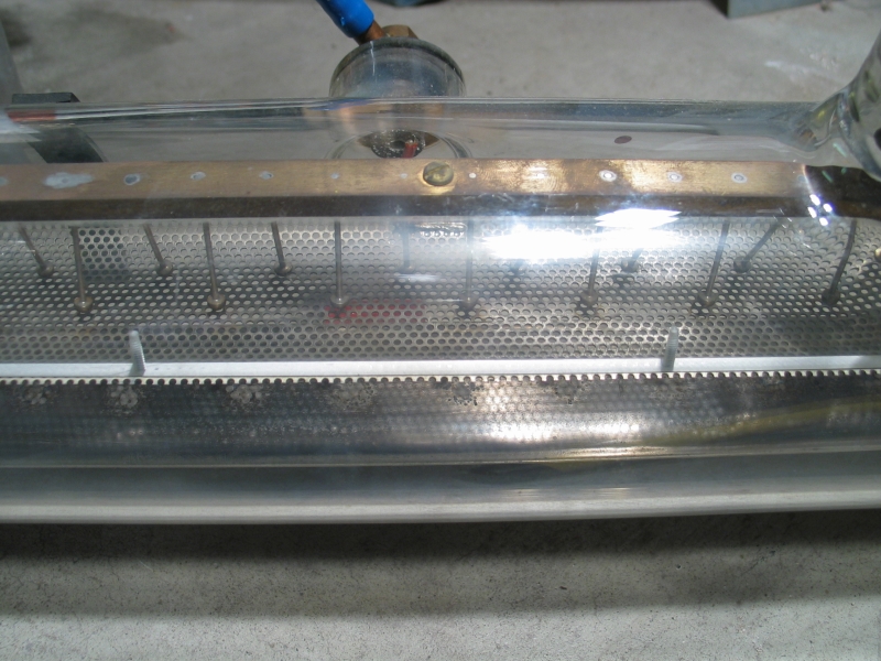
(Click the small image if you want to see an enlargement.)
As I’ve already mentioned, it is possible to add a structure to the laser that steals a small amount of energy from the discharge, and uses it to preionize the channel. One way to accomplish this is to run a thin wire alongside the channel, typically somewhat closer to one electrode than the other, and connect it to the more distant electrode through a small capacitor. When the voltage across the channel begins to rise, the small capacitor is uncharged, and so the field strength between the wire and the electrode it is close to increases more rapidly than the field strength between the two main electrodes. A corona discharge develops, which charges the small capacitor and sprays UV and ions into the gas between the main electrodes.
It is also possible to use either one wire and one of the electrodes, or two entirely separate wires, and just run a milliampere or so of DC. (This technique was used in the Rebhan et al. laser, which developed over 1.5 MW and produced pulses 18 nsec long; see the references.) The advantage is that it does not steal energy from the main discharge. The obvious disadvantage is that it requires a second power supply, and that the wires must be either well off to the side, or must be shielded a bit from the electrodes so that the discharge avoids them. Even so, this technique seems to be robust and reliable.
A related method, best if the wall around the channel is thin, has a broad conductive strip on the outside, connected to one of the electrodes. Corona develops on the inner surface of the wall.
A method that is common in CO2 lasers
involves semiconductors. This turns out to be quite
practical for nitrogen lasers, and is extremely easy to
construct. I have built a laser in which I simply coated
one inner wall surface with epoxy and poured carborundum
grit on it. When the epoxy had set, I poured off the
excess grit. Then I attached the wall to the channel,
making sure that there was contact between the
electrodes and the semiconducting material. (I did leave
a blank space, parallel to the electrodes, without any
silicon carbide on it, for sparks to jump across; but
that may not be necessary.) This laser ran with 1
atmosphere of helium in it, and did not require a vacuum
pump.
There are people who try to claim that because a
nitrogen laser doesn’t have mirrors (or has only
one), and does not have a defined mode structure, it
isn’t a laser. It seems to me that despite the
fact that Gordon Gould specified a cavity in his
original notebook, in 1957, when he invented the term
“LASER”, the acronym does not have the
initials “FPR” anywhere in it. Moreover, any
device that operates by means of Stimulated Emission
produces light that has characteristics you just
don’t get from other sources. In addition, it is
perfectly possible to put mirrors on a nitrogen laser;
it just isn’t necessary.
Various of these are at the end of my
rant about the explanation of the Scientific American laser.
As a bit of a postscript, if you aren’t already on
the LASERS mailinglist and you would like to join,
try this page.
To a page about my initial effort to produce a high-performance nitrogen laser
To a page about my continuation of that effort, which resulted in a laser that puts out about 100 kW and can operate without a vacuum pump
To a “How-To” page about that laser
To an interim page about my effort to scale up a published design in order to enhance its performance
To a page about my recent (starting mid-August, 2006) redesign of the “DKDIY” laser, which resulted in significantly enhanced performance
To a brief “How-To” page about building the revised design
To a page about my current (late 2006) effort to build a less-expensive laser with even better performance
My email address is a@b.com, where a is my first name (jon, only 3 letters, no “h”), and b is joss.
My phone number is +1 240 604 4495.
Last modified: Mon Jun 22 11:00:21 EDT 2020