(15 August, 2006, ff)
This page details the construction of a nitrogen laser that is a follow-on to the “DKDIY”design I published here a few months ago, along with a “How-To” page. Because this material is being written substantially as a historical track of the project as it is taking place, it is not necessarily organized logically. When the design is fully stabilized I will try to provide a “How-To” page for those who want to build a laser of this type.
(Note, 2006 September 27: Between the “DKDIY” laser and this “DK-Plus” laser, I experimented with a larger design, which operated, but not at the performance level I had expected. This appears to have been caused by several factors, some of which I may explore [and, I hope, correct] by returning to that laser and rebuilding it, now that I have this one working well.)
(Note, 05 October, 2009: I am reworking this laser, and I hope to get somewhat better performance from it than I originally did. There are a number of issues involved in the rework, which I discuss at one or two places on this page, and in a second page specifically devoted to it.)
I would strongly suggest that you read through at least
the early sections of this page and all of the following
page before you attempt to build one of these, as that
will help you avoid some “gotchas” that I
encountered.
This laser uses high voltages, and capacitors that can
store lethal amounts of energy. It puts out an invisible
ultraviolet beam that can damage your eyes and skin. It
is important to take adequate safety precautions and use
appropriate safety equipment with any laser; but it is
crucially important with lasers that involve high
voltages and/or produce invisible beams!
The first version of this laser was intended to provide performance at least as good as that of the classic Scientific American “Amateur Scientist” nitrogen laser design, but using “doorknob” capacitors instead of circuit board, and with a triggered spark gap as a switch, rather than a free-running gap. It is a “Voltage Doubler” circuit, often mistakenly called a Blumlein. I chose the doubler circuit because it is relatively easy to construct, and because it parallels the circuit of the SciAm design.
That first “DKDIY” laser used a dozen laser-grade SrTiO3 doorknob capacitors. It reached threshold at about 12.4 kV, and developed a little over 100 kW at about 20 kV. The channel was 22 mm across and about 45 cm long, and the electrodes were pieces of extruded aluminum carpet edging.
This revised version will use 16 doorknobs, and will have electrodes a bit more than 80 cm long, with capacitors along the middle 45 cm or so. I originally intended to use a piece of brass shim stock as the cathode; shim stock has a fairly sharp edge and so should provide some preionization by generating corona early in the discharge cycle. It’s a bit thin in comparison with the anode, but may work. If not, I can always try a packed-blade cathode, or add some extra preionization.
(Note, added later: I soon abandoned the idea of a thin sharp-edged cathode, and shifted to two identical electrodes.)
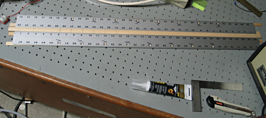
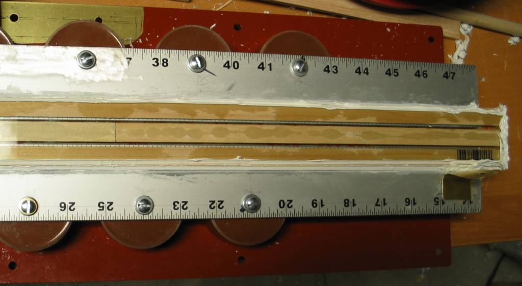
My original intention for this enlarged version was to use carpet edging again, at least for the anode; but when I examined the pieces I had on hand I discovered that they were not very straight. Straightness being a real issue, I changed my mind and turned to something that does have a straight edge: an aluminum ruler. The ones I’m using were originally 4 feet long, but I have cut them down to 32 inches, a reasonable length for this head. They are 2" wide, which fits well, and 1/8" (~3.25 mm) thick, also very reasonable, though that is significantly thicker than the previous electrodes, which had a cylindrical edge only 1.5 or 2 mm in diameter. My hope is that the capacitors I’ve added will be enough to let me pump the additional channel volume. (It is important to deposit sufficient energy into the discharge, in order to be sure that the laser will operate well above threshold. Typical high-performance nitrogen lasers seem to dissipate at least 40 joules per liter of active discharge, and some exceed 100 j/l.)
Following an idea developed by Jarrod S. Kinsey, I am constructing the sidewalls and spacers of this new head from wood, a construction material that is widely available, extremely tractable, and relatively inexpensive. (I may provide windows through the sidewalls to permit observation of the discharge in the channel.) Wood tends to be slightly conductive at high voltages, but I will be using walls that are varnished, which should reduce the conductivity somewhat. If some conductivity remains, there is a small chance that it may provide a bit of preionization, in much the same way that a semiconductor plate does.
(Addendum, 27 September, 2009)
Most wood is a bit porous, which is a problem. (It turned out to be a problem even with the varnished yardsticks I used in the head of this laser.) Consider a nitrogen laser running at 50 Torr; if there is a leak that admits 2 Torr of air, the gas mix contains more than 3/4 of 1% oxygen, which is too much for optimal performance. (A small amount of oxygen is okay, and in fact at roughly 1/3 of a percent you may see slight improvement in performance. Beyond about half a percent, however, oxygen degrades the performance of the laser.)
If you use wood, make sure that you either coat the interior surfaces with something that is relatively impervious to air, or soak the wood in something that will solidify and make it impervious. One way to do this is to mix epoxy with isopropyl alcohol (at least 91% pure; 99% pure is better), and brush it on. You probably want the epoxy to be just liquid enough that it brushes reasonably easily; if it is too dilute it has a tendency either to fail to cure, or to cure to a soft and rubbery condition. After the first coat of epoxy has had time to cure, repeat the process until it no longer soaks in; this will almost certainly take several coats. When all of the epoxy has fully cured, the wood should be sealed well enough to be usable.
There are certainly other ways to accomplish this, but
you will want to think it through carefully. Some
paints, for example, continue to emit solvent vapors for
months. These may (or may not) interfere with lasing.
There is only one real way to find out; and if the
answer is ‘yes’ you will probably be obliged
to rebuild the head, which is (believe me) a real annoyance.
Here is the circuit diagram of the laser:
The capacitor labelled “Start Cap” is present mostly in order to produce a current of a few dozen Amperes in the spark gap very quickly when it is triggered, to help develop a substantial conduction channel in it. The manufacturer recommends pushing at least 10 Amperes through the gap to get it to switch properly. This probably takes only a few dozen pf, which can be furnished by a rather small doorknob; it is, though, important to keep the connections fairly short and the inductance down, as you have only a brief time in which to accomplish the job: a good spark gap should switch in a few tens of nsec. (Please note that although it is possible to make subnanosecond spark gaps, the designs I’ve seen were pressurized to about 1500 psi and were built into cylindrical transmission lines.)
I have shown a charging inductor across the channel, but a charging resistor works better in some designs, and I will probably try both to see which is appropriate for this laser. I have also shown a small capacitor that connects to a dot near the cathode. The dot represents a thin wire that is strung along the entire length of the head, and serves to preionize the laser. This is discussed in the text, and is the initial configuration I’ve chosen to try; I may move to a different preionization method later.
(Note, added much later: I did. See below.)
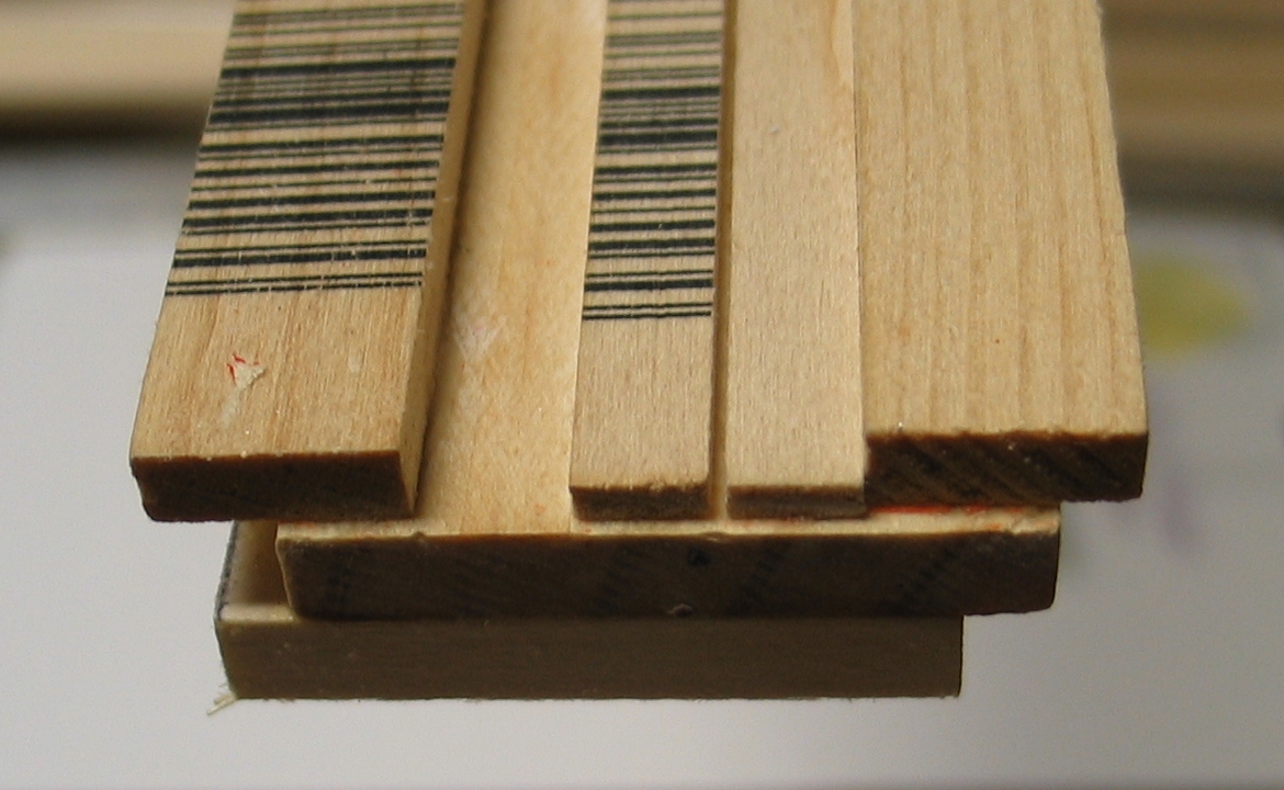
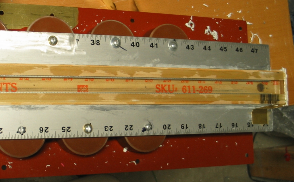
The sidewalls of the channel are wooden yardsticks, about 1.5" wide and just over 34.5" long, cut down from their original length of 36". I have widened the lower sidewall by gluing smaller pieces of wood to its edges, as it was just a bit too narrow to work well — I want to have the electrodes 25 mm apart, and I need to have room to attach spacers to separate the electrodes from the sidewalls so the discharge doesn’t track along the surface. (At the bottom of the left photo below you can see the 1" spacer sitting on one of the rulers, before I added extra wood at its edges. You may be able to tell that the spacers, which are visible in the photo on the right, are farther apart than they could have been with the unmodified ruler.)
The electrodes are 32" long, but the capacitors are restricted to the center 23" or so. This should help avoid sparking at the ends of the electrodes, where the longer current path provides higher inductance. We hope. [[NOTE: As of 19 August, 2006 I am revising my thinking about this, and moving toward a slightly different head design. See below.]]
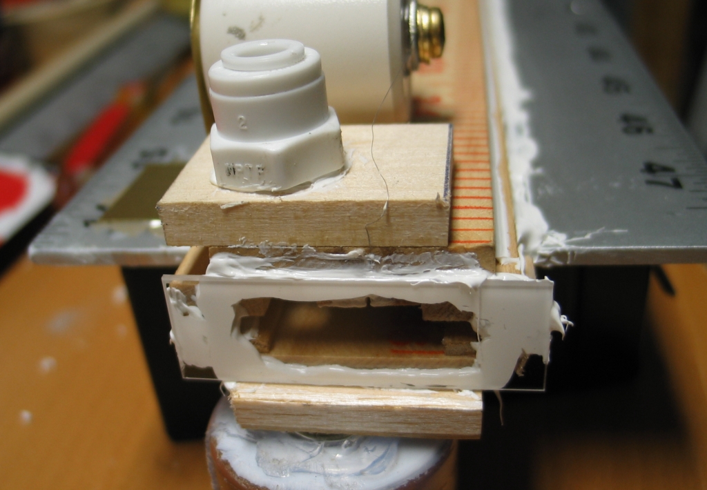
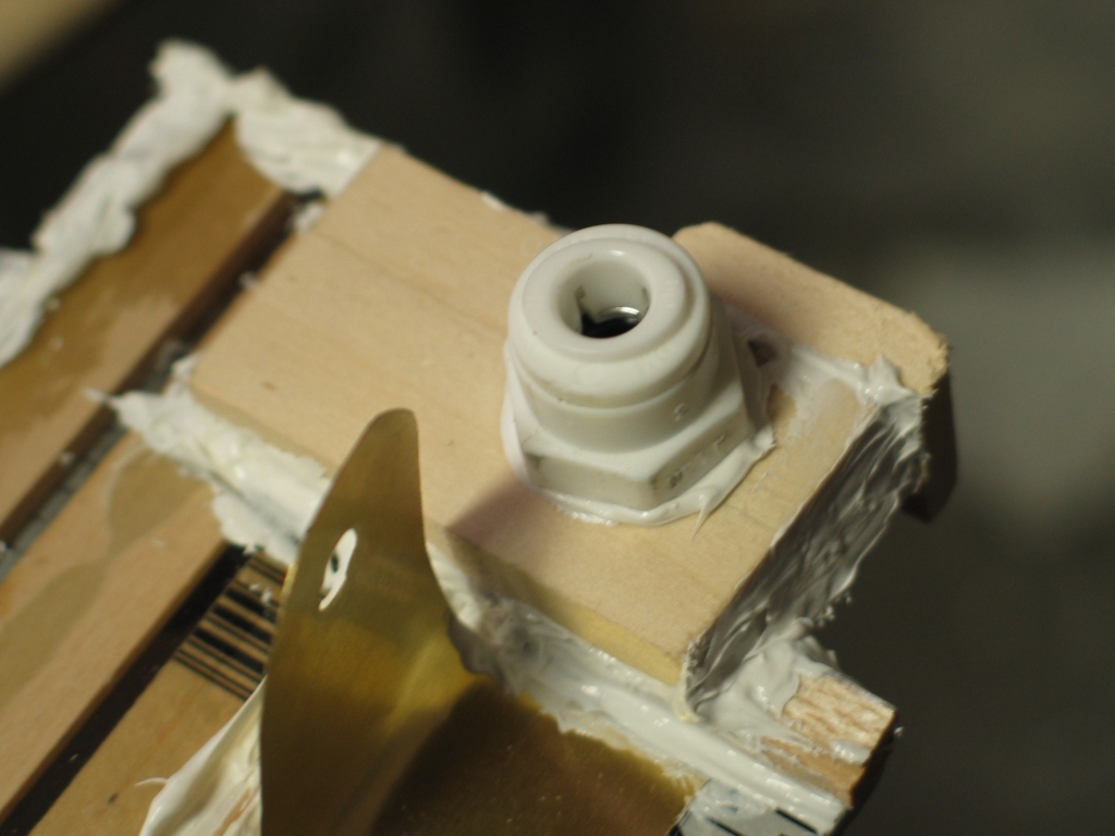
Here is a photo showing the underside of the roof, with one of the gas ports visible near its left end; the bottom wall of the channel, with its spacers to position the anode and cathode; and the left end of the anode.
I have to decide, very soon, whether I expect to run this laser under vacuum. If so, I will need to coat the inner surfaces of the wood with something, to reduce outgassing. If I’m only going to use atmospheric pressure helium with a small amount of nitrogen, on the other hand (as I did originally), I don’t think I will worry about that. The rulers are already varnished or coated in some manner, and the other bits of wood I’m using are fairly small. I am tending to think that atmospheric pressure may be a good bet, as I am not sure how well the rulers, which are of low quality, would stand up to vacuum and its attendant stresses.
(Note, added much later: they stand up just fine to
the stress, but they leak unless carefully sealed.)
(19 August, 2006)
As I continue to think about this laser, I am changing
my mind about how to proceed with it. (This should come
as no surprise to anyone.) The base design takes a
replaceable head, and I have at least three ideas for
heads. The one I now think I will build first has 1/8"
thick aluminum rulers as both electrodes. These will be
separated by 5/8", just under 16 mm (I did a rough
calculation last night that suggests better chances of
good performance with tighter spacing than I used in the
original DKDIY laser), and will be about 35" long, to
help prevent sparks at the ends. Because of the
narrower channel, the rows of capacitors will end up
being 4" apart instead of 4.5"; I will probably put the
“lower” row 1.5" upscreen, rather than at
the 1" position shown in the diagram.
I am becoming more and more convinced that preionization
is the key to high performance in low-pressure nitrogen
lasers (in TEA lasers, it appears to be essentially
mandatory), so I am also going to add a preionizer, a
thin nichrome wire in the first version. I intend to
attach the upper sidewall in such a manner that it is
easily removed. That will let me test other
preionization methods without totally rebuilding the
head.
My rationale is that this head will be extremely easy
to construct, and should swiftly provide some much-needed
information about preionization methods. It should also
work well, assuming I can preionize it sufficiently.
Here is the tentative layout of the laser, based on an
8" x 34" brass kickplate I acquired at the hardware store:
The asymmetry, with wider open area “above”
the “upper” row of capacitors (in case the
print in the picture is too small to read) facilitates
making connections to the spark gap, which is not shown
in this diagram.
I also acquired some square extruded aluminum tubing to go
under the baseplate to stiffen it — the head is long,
and probably not stiff enough by itself to force everything
to stay lined up.
The aluminum rulers I’m using for electrodes are
just 2" wide, and the spacing between them is 5/8",
which sets the spacing between the rows of capacitors
— I have to be able to bolt the electrodes to
them. Very fortunately, that spacing just accommodates
the wooden rulers I am using for sidewalls with a wee
bit of “wiggle room”, as they are 1 &
7/16" across. If it had been any closer, I would have
had to widen the laser channel or adopt a different
design.
For preionization by wire, there are two obvious modes:
passive, and active. I have discussed these on
the root page of this series, but it’s easy
enough to do a brief review here.
Passive: You typically use a single wire for
this. It is strung along the channel, typically off to
one side so it isn’t in the middle of the
discharge (though people have actually used wires spang
in the middle), and usually considerably closer to one
electrode than the other. You connect the wire through a
capacitor to the more distant electrode. When you fire
the laser, the rapidly-rising voltage across the channel
appears on the wire (the little cap is uncharged, and
essentially looks, at least for a brief period, like a
dead short), and a corona discharge develops. This
provides ions and UV, which preionize the channel.
There are two modes of thought about positioning and
connecting the wire. One says that you should put the
wire close to the cathode and connect the small
capacitor to the anode, because you want your
preionization to be at the cathode. The other says that
the cathode emits electrons, so you should put the wire
close to the anode and connect the little capacitor to
the cathode, which makes the preionizing wire
effectively be the cathode at the beginning of the
discharge cycle. I think I fall into the former category
(wire near the cathode, capacitor to the anode), but I
have not made any study of this, so you are advised not
to trust my opinion. On the other hand, that is the
configuration I am building for the initial tests of
this head.
An alternative that doesn’t involve wires or
capacitors is to use a sheet of semiconductor, off to
one or both sides of the discharge. The conductivity of
the semiconductor has to be chosen moderately carefully,
but this technique (which was developed with CO2
lasers, works quite well. I have made one of these by
putting a thin coating of epoxy onto a sidewall, and
applying fairly fine silicon carbide abrasive grit to it
while it was still wet. I also left an empty channel
somewhere in the middle of the wall, so that sparks
could jump from one semiconductor “electrode”
to the other, but I doubt that this is necessary. On the
other hand, it could provide an easy way of compensating
for semiconductor material that’s a bit too
conductive.
Important note: passive preionization steals energy
from the main discharge. If you don’t steal enough,
you don’t get adequate preionization. If you steal
too much, the main discharge doesn’t get enough.
Either way, performance suffers.
Active: You can do this with one or two wires.
Active preionization requires a separate power supply,
and draws about 1 mA of current, either between one wire
(or two, if you can make sure they both source current)
and one of the electrodes, or between two wires placed
at either side of the channel so that the corona
discharge crosses through the channel.
An oil-burner ignition transformer is a convenient
source of high voltage (this technique tends to require
only about 5-10 kV). If your oil-burner transformer has
a centertapped secondary winding with the centertap
connected to the case, the obvious circuit is a bipolar
full-wave rectifier, similar to what you might build for
a low-voltage bipolar supply. Most neon-sign transformers
are constructed the same way, and a small one could be
used for this. Here’s the circuit:
Because this has two outputs, it suits itself well to
the use of two wires.
In use, we would like to forget about the ground
connection, but it is important to be careful because
one side of the HV supply for the laser is also
grounded. I am guessing that if you put a large
resistance to ground from the centertap of the
transformer, and only moderately large resistors (for
current limiting) to the corona wires, you should be
okay. Remember that all resistors need to be able to
withstand rather high voltages. Remember also that
your HV rectifiers should be able to withstand 6 to
8 times the rated voltage. Here’s the logic:
Granted, this is expensive; but it will save you much grief.
As I mention above, I am going with single-wire passive
preionization for the first version of this laser.
(20 August, 2006)
I have marked and drilled the holes in the electrodes,
and I’ve almost completed the sidewalls.
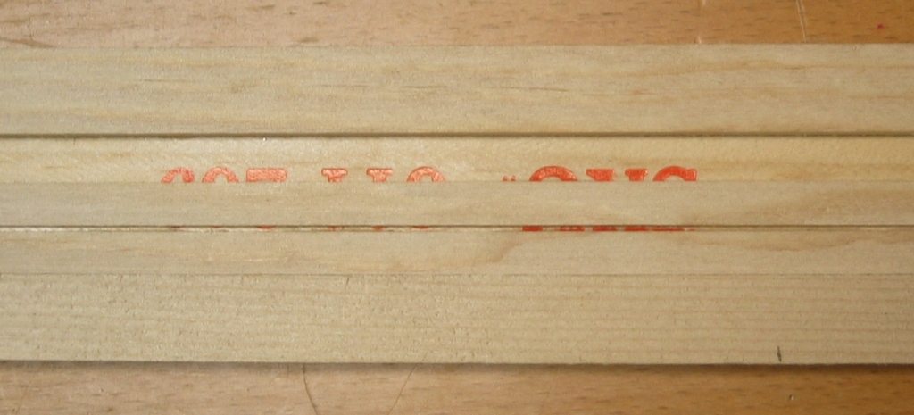
I had set the electrodes out on the bench with the
spacer between them...
...and was about to RTV the floor of the channel on,
when I realized that after I flipped the resulting
assembly over, I’d be trying to connect to the
doorknob caps through the painted numbers. This was
clearly suboptimal, so I set the floor aside and
configured the roof. (I will have to remove the anodized
coating from the surface anyway, so it isn’t that
big an issue, but I think it will be instructive to have
the numbers visible when the laser is finished.)
Because I intend to use a wire preionizer for this
iteration, I wanted to have a narrow space for the wire
to sit in, down between walls of some sort, to help
prevent the discharge from heading for the wire, which
it might otherwise do. This is a wooden head (much like
my own, argh), so I decided to use two strips of wood; I
pushed the first one into place with a straightedge and
held it while the CA (cyanoacrylate) set. Then I put
pieces of cardboard between it and the second one while
gluing that into place:
The result appears to be a moderately straight groove,
which will probably serve. Now I have to figure out how
to glue a 0.0031"-thick nichrome wire into place in the
bottom of that groove, without covering the wire with
glue. I’m thinking about diluting some epoxy with
isopropyl alcohol, painting a thin layer of it into the
groove, letting the iso evaporate, and then laying the
wire onto the surface of the epoxy layer, which will be
quite thin by that point. Because I don’t need
much physical strength, I don’t have to worry if
the epoxy starts to harden before I get the wire onto
it. In fact that might even help, as the wire would be
less likely to get covered if the epoxy is already a
little stiff.
The real problem with this arrangement is that the wire
is a wee bit too close to the cathode. I should have
used a slightly wider spacer on the cathode side. Such,
however, is life. We’ll see how well it works, or
doesn’t.
Once I have the gas ports and the wire in place, I will
RTV the roof on.
(Early AM, 22 August, 2006)
I have dropped the 3-mil nichrome wire into the groove
I made for it, drilled the holes for the gas ports and
installed the connectors, and RTVed the roof to the head.
If I do this again I may design the thing to make
installing the wire easier, and I may also opt for wire
of larger diameter. Still, it’s an interesting
test, and I have another wooden ruler if I decide that
I need to fall back to semiconductor preionization.
Once the electrodes and the roof of the channel are
firmly attached to each other, I can set them on the
baseplate to check the hole positions. (I don’t
want to drill the baseplate until I’m sure
I’ll be able to assemble the laser.) Then I get
to:
At that point, I think I’ll be ready to start testing.
(24 August, 2006)
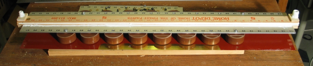
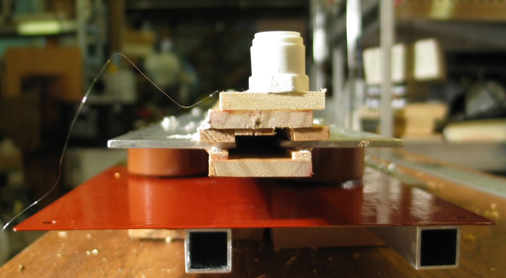
Here’s a test of what the machine will look like
when I assemble it:
Notice that there are no end windows on the head yet,
the preionization wire is not connected to anything,
and the spark gap is not present. Several other things
also need to happen before this will be a laser, but
at least we can now get a sense of what it will be
like.
Because the rulers I’m using for electrodes are
anodized, it was necessary to clear the areas where
they are going to connect to the capacitors. I figured
that a wire brush on a Dremel™ or other rotary
tool would do the job, and a test showed that this is
correct:
I have brushed the 16 contact areas for the main caps,
on the undersides of the electrodes, and 2 extra areas
on the top of the anode, one at each end, for pieces of
brass shim that will go to the caps that drive the
preionizing wire. As of now, I am planning to use 760 pf
doorknobs for those, partly because I actually expect
the wood to do some of the work for me.
It seems extremely likely that doorknob caps with
broad terminations have lower inductance (and
are therefore faster) than doorknobs with narrow
terminations. Sometimes, there isn’t much
you can do, but a few types can be improved fairly
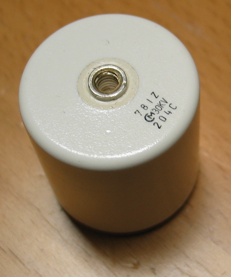
easily. Here is a little MuRata 760 pf cap:
You can easily see that although the termination is just
a narrow ring around the #8-32 threaded hole, there is
actually much more metal present. Unfortunately, it is
covered with epoxy. Fortunately, you can do something
about that. First, you get to clean the epoxy off:
Unfortunately, I only have two hands, so I can’t
show you how I hold the knife with one hand and rotate
the capacitor with the other; but I trust you get the
idea.
Here is what the cap looks like when it is thoroughly
clean:
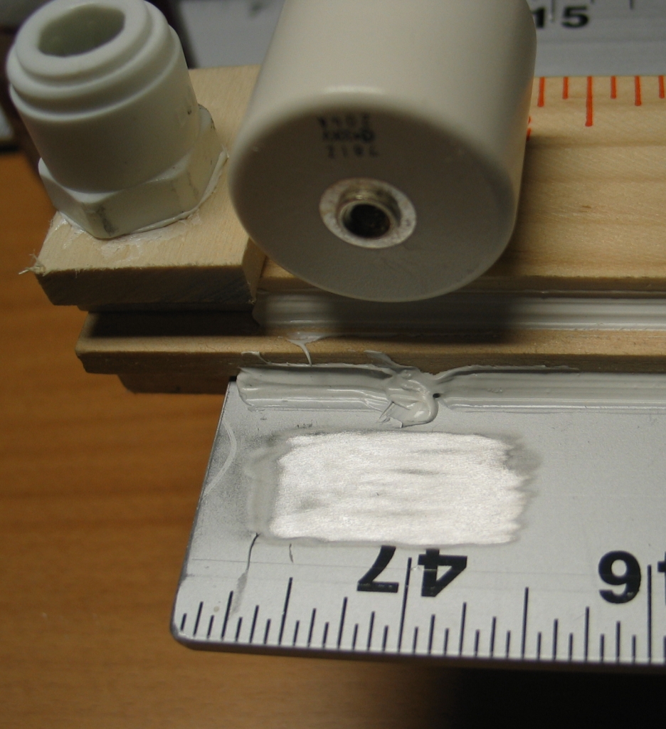
You then use silver-loaded conductive epoxy to put a #14
brass washer (or a 6mm washer, as I discovered when I
ran out of #14s) on the cap. The next photo is just to
give you a sense of size and fit; I have not yet epoxied
the washer on. If you don’t have (or cannot afford)
silver epoxy, don’t worry about it. If you attach
the cap to your circuitry with reasonable pressure, you
will still get good conductivity. Do remember the
washer, though.
The washer is just thick enough to match (more or less)
the height of the original termination, and the hole is
just a bit wider than the ring. Why the manufacturer
didn’t simply make these caps with full-width
terminations, so we wouldn’t have to go through
this idiotic rigmarole, I have no idea.
We now return you to your previously scheduled programming...
(Midnight, 25/26 August, 2006)
I have almost completed the assembly of this head. The
windows are on (though, as you will see in the photos,
the RTV has not yet set on the second one, so it is
still propped into place), and the preionizer is ready
for use.
I have discovered a pleasant thing: an ordinary
hole-punch for paper will (just barely) make a hole in
5-mil brass shim stock that is only a little bit large
for a #10 machine screw. It was even tolerable for the
shims on the preionizer, which currently take #8 screws.
I don’t know how long the device will last in this
service, but it is certainly convenient. Cost me a whole
dollar at an office supply store.
Once all the RTV has set, I may be able to perform some
preliminary testing on this design. I have a GP-70 that
is already mounted on brass shims, and although it
won’t be as fast as a properly mounted gap, it
should give me some sense of whether this design is
viable. Proper operation, however, will want a GP-14B
mounted on much wider pieces of shim, for good tight
coupling and better performance. That should be fairly
easy to arrange, fortunately.
(27 August, 2006)
I have now tested this arrangement, using the GP-70
mentioned above. The device discharges, but does not
lase at charging voltages up to 20 kV.
I have tried a variety of fills and pressures, and I
have tried increasing the drive capacitance on the
preionizer. There are some indications of sparking at
the end of the channel that I can see, and I am now
thinking about retreating to a head with glass walls,
though I may very well use wooden flats as
semiconductors for a preionizer similar to the one I
used on the original DKDIY device. I may also sandpaper
the edges of the electrodes to remove the anodizing
from them.
Another possibility is to try 900-pf capacitors, which
should be somewhat faster than the 2-nf doorknobs that
are currently in place; but they also store less than
half as much energy, and I doubt that the speed increase
would be great enough to compensate — that should
change with the square root of the capacitance, whereas
the energy storage is linear at a given voltage.
Time to sit and think for a while...
(later, that same evening)
...but not for too awful long. I have just started
construction of the new roof for this channel. If
the roof isn’t enough, I can also build a new
floor, but let’s do this one step at a time.
I have some glass bars, about an inch and a half across
and 1/8" thick, but they are only 30" long, and I need
something a lot closer to 36", so I am cutting and
gluing. Clean, straight ends are easy to epoxy if you
are not concerned too much about strength, and in this
particular case I think most of the stress will be
across the bar when I pull vacuum on the head, so
I’m not going to worry about it too much. 1/8" of
glass should be about as strong as 1/4" of wood, and the
wooden roof stood up to the vacuum reasonably well.
I am going to try wooden preionizer bars on this roof,
with silicon carbide grit on them. I will leave 1/4"
separation between the flat wood pieces, and that should
be enough to get good operation. It will also let me look
inside the head and see a little of the discharge, which
will give me some information that is hard to get by
other means.
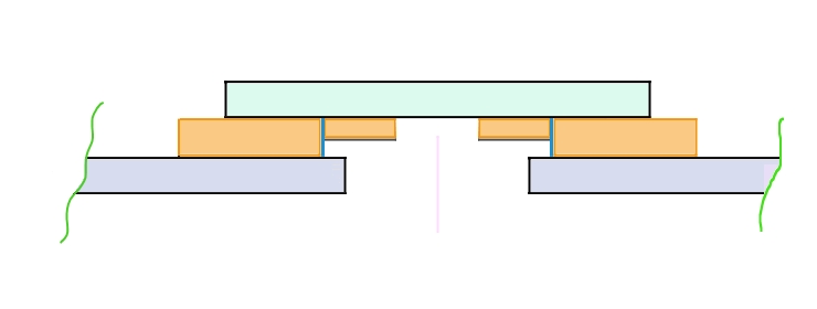
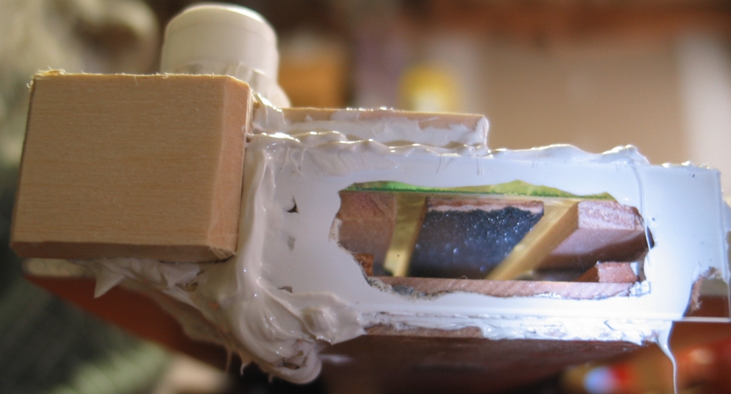
Here is a cross-section of what I am expecting the new
roof to look like:
(Glass is shown in pale blue-green; wood in brown;
electrodes in purplish gray; silver paint in blue;
silicon carbide in gray. The pale pink vertical bar
marks the centerline. The electrode spacing is
unchanged, as is the floor of the channel, which is not
shown in this illustration. Glue and sealant[s] are also
not shown.)
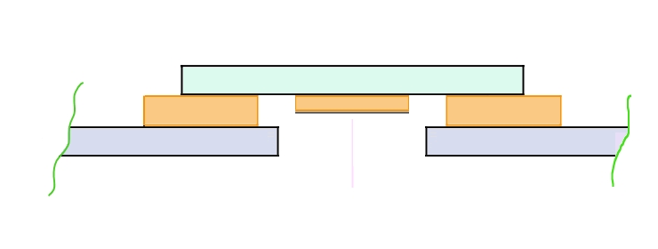
(early evening, 27 August, 2006)
Alternatively, I could dispense with the silver paint
and just put a silicon-carbide-coated strip down the
middle of the open space, possibly 1/2" wide, or maybe
even the full width (3/4"). This would obscure my view
of the discharge, but would probably preionize the
channel adequately.
(early AM, 28 August, 2006)
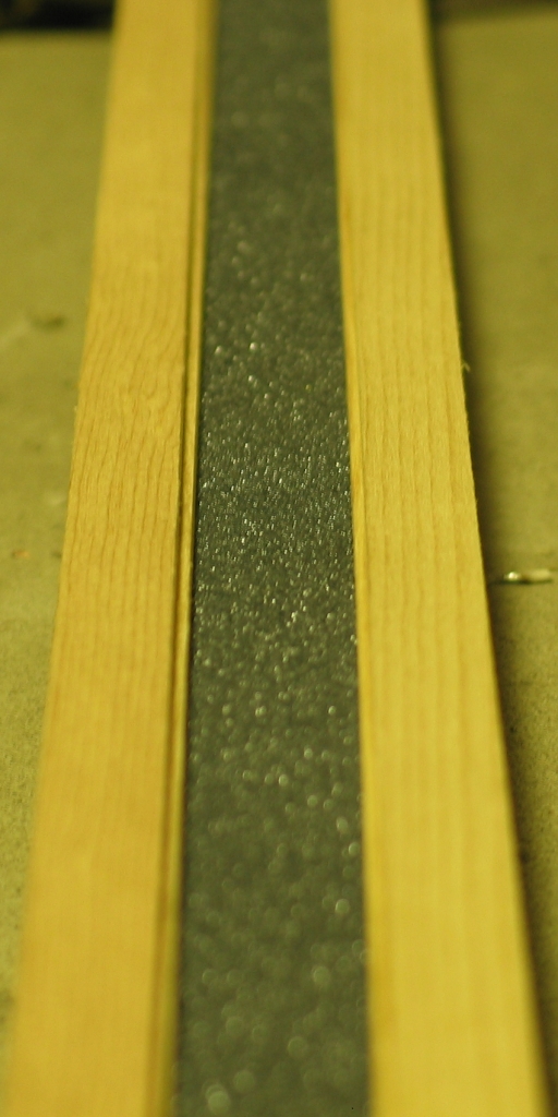
...And that’s exactly what I did. Here is a
diagram:
Here are two photos, one taken with the top sidewall
sitting in place, before I made the preionizer, and
another taken after I put the preionizer in and put RTV
onto the sidewall to seal it and hold it in place:
The wood I had on hand that was the correct width was in
2-foot sections; you can see the joint in the preionizer
somewhat to the left of center in the second photo.
I still need to create the gas ports, but that should
be relatively straightforward. Then I can resume testing.
I should note that while I was setting up the new
“roof”, I also acquired some 1500-grit
sandpaper and removed the anodizing from the upper edges
of both electrodes. I wasn’t able to get the
entire face, but at least there is now an exposed region
of aluminum, and it is close to the edge of the preionizer,
which should help that work correctly.
(early afternoon, 28 August, 2006)
I have now built the gas ports. With any luck I should
be testing at room pressure within a few hours, when the
RTV has begun to harden. My apologies for the slight
motion blur in these photos; the light was less than
optimal. In fact, I had to shine a white LED up into the
end of the head to show the surface of the preionizer in
the second photo.
Notice that the preionizer extends well past the ends of
the electrodes. Also note the slanted bottom on the gas
port section, which unfortunately is not easily visible
in either photo. I built both of them this way, to
minimize the exposed areas on the sides, and also for
strength. As Bucky Fuller pointed out, a triangle
resists deformation a lot better than a square does.
(Yes, I know, the side-plate is a square, but that’s
because I had it handy; it is covering a triangular hole.)
(early that evening)
Initial tests give me lots of bright sparks from the
electrodes to the preionizer, and under some
circumstances there are lots of very small sparks, a
good sign. I suspect that the preionizer conducts a bit
too well, as I do not appear to be getting a
“regular” discharge, at least with helium at
1 atmosphere; but we’ll see how things go under
vacuum ...after the RTV sets, probably tomorrow morning
unless I just can’t stand it. (I certainly
should stand it — the stuff is still quite
soft now, and it won’t be even moderately hard for
at least another 12 hours.)
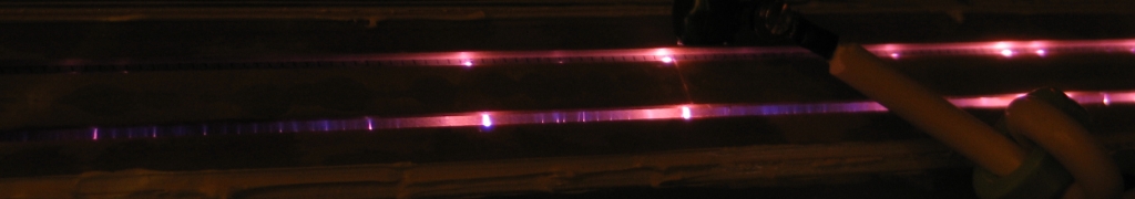
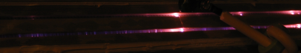
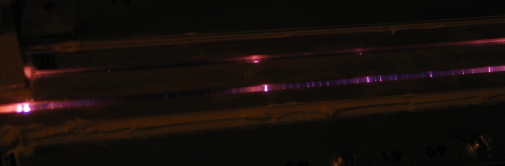
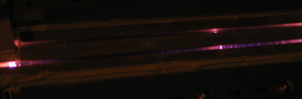
In the meanwhile, here are four views of part of the
channel, showing typical shots. The brighter sparks in
the laser are pink because the head is filled with
helium. If you want more detail, btw, change ".10c"
in the filename to ".22c". That gets you the crop I
made from the original image, unscaled. I think the
upper ones are in better overall focus than the lower
ones, but the right sides of the lower ones are okay.
One saving grace of this head design, btw, is the fact
that I can scrape the current preionizer off and put a
narrower one on, if I decide that it really is just too
conductive. It wouldn’t be fun, but I could do
it. Alternatively, I could just raise the roof a bit by
adding more spacers, which would put the preionizer
further from the electrodes. Again, annoying; but
certainly possible to do, which is good because I expect
to be doing it in a day or so.
(early AM, 29 August, 2006)
Based on what you can see in the photos above and on my
general sense of the behavior I observed it seemed
pointless to wait, so I have just removed the
“roof” and added an additional 1/8" of
spacing. It was certainly annoying, but I knew I might
have to do it, so I’d set up the head to make it
as easy as possible under the circumstances, and it
really didn’t take very long. It’s
done now, and when I wake up in the morning I should be
able to resume room-pressure testing. Later on
we’ll see about leaks...
(around 0900, 29 August, 2006)
Initial results at room pressure (arcs and sparks that
don’t actually appear to be going to the
preionizer) lead me to think that 1/8" may actually have
been a bit much, and I may eventually remove those
spacers and replace them with 1/16" ones; but I want to
do some testing at reduced pressure first, as that could
change the behavior significantly. Have to wait until the
RTV gets much stiffer, though, before I will feel good
about pulling vacuum on this head. Maybe tonight...
(early that afternoon)
I decided to apply Jarrod Kinsey’s excellent
methods: used a piece of polyethylene hose as a
stethoscope to find the leaks, and stopped them up with
a rather rubbery type of hot-glue. Took me perhaps 30
minutes to clean up just about everything (or so I
thought; see below for more about this), after which I
resumed testing. As far as I can tell, all I’m
getting is bright (and dim) sparks from the electrodes
to the preionizer, even with the spacing as wide as it
now is. I am somewhat surprised, but that’s what
I’m seeing. I want to try a variety of fill
pressures and mixtures, but I have not been able to do
much testing yet — the vacuum pump emits an oil fog
that I really don’t want to breathe; I have to
figure out a way to trap that stuff.
As long as I have this problem, let’s talk about it.
I have a lovely commercial roughing pump. Only one
problem: if it runs for more than a few seconds against
even a light load (for example, a nitrogen laser), the
exhaust becomes a nasty fog of oil droplets. In the best
of all possible worlds, there would be a neat way to
catch the fog and turn it back into liquid oil, which
would then drip back down into the pump: after all,
that’s where it belongs.
In the next-best world, there would be a way to catch
the fog and remove it from the exhaust of the pump, even
if there weren’t any good way to turn it back into
usable liquid oil.
In the mediocre (real) world, one runs the exhaust hose
to the great outdoors. Vacuum-pump oil of the ordinary
sort is a relatively innocuous material, and there are
bacteria in the soil that will eat it if they can get
their grubby mitts on it. For various reasons, however,
including the fact that vacuum pump oil is expensive, I
would prefer to let those bacteria eat other things.
There is a very pleasant way to remove dust and aerosols
from the air. It is called a Cottrell precipitator, and
it is a fine use of HV DC. You can operate a Cottrell
from an electrostatic source, and I believe that under
some circumstances you can even do it with AC.
Basically, you make an open-air capacitor; let the air
flow past the plates, and even modest amounts of corona
will charge the particles, which then stick to plates
charged one way or the other. (I have several commercial
electronic air filters that do this. They are quite good
at removing dust; I think the usual rating is 97% per
pass, and the size of the particles is not particularly
an issue, the way it is with HEPA or other mechanical
filtration methods. After room air passes through such a
device a few times, there is very little particulate
matter left in it. Unfortunately, a room-air cleaner is
not easily adapted to this service, so I’m going
to have to build something.)
I happen to have a nice old oil-burner transformer here,
courtesy the very kind fuel-oil place a door or two
down, which can serve as a source of high voltage. It is
time to do a spot of construction...
(late that evening)
I suspect that I have the “plates” (actually
pieces of brass screen) too far apart, as there is still
fog coming out of the pump. I will have to figure out a
way to reduce the spacing. I tried putting rectifiers
in, to make DC instead of AC, but it did not appear to
change the performance. Too bad — it would be
really nice if this thing worked. I want to get back to
messing with the laser.
(next morning, 30 August, 2006)
Well, hmmm. It may be simpler than I had thought.
This PDF file
shows a simple design, and comments that oil droplets
(at least in cigarette smoke) tend to be positively
charged, which tells me that I want DC and that I want
the negative pole in the middle. When I get a chance, I
will probably go get some PVC tube with a thin wall, and
see how this configuration works. That, however,
probably won’t be until tomorrow, as I am
scheduled all day today with other stuff. (Sigh.)
(NOTE, added 06 October, 2009: That PDF file is suspect. Milan
Karakas has found other information, and has verified it by
experiment. It is clear that insulating the conductors is
not a good idea, at least under ordinary circumstances.
See below for a rebuild of this device during October and
November of 2009.)
(31 August, 2006)
I took a piece of #8-32 threaded rod about 2 feet long
that was lying around, a couple small pieces of
fine-mesh brass screening, a piece of 3/4" PVC pipe from
the hardware store, some plain copper wire, and a
fitting to hold the pipe and sit on the outlet of the
pump, and constructed a device.
First, I made a hole in the middle of each piece of
screen and used hot-glue to attach them to the ends of
the pipe. Then I used a nut and a lockwasher on the
underside of the top screen, and an acorn nut and a
lockwasher (and a drop of hot-glue to prevent the
vibration of the pump from wiggling the acorn nut loose)
on the upper side, to position the piece of threaded rod
so that it hangs vertically in the center of the pipe. I
left a tab on the upper screen, to connect to the
negative terminal of my impromptu power supply. Then I
wound the copper wire around the outside of the pipe,
holding it in place with a tie-wrap at each end. That is
now connected to the positive terminal of the supply.
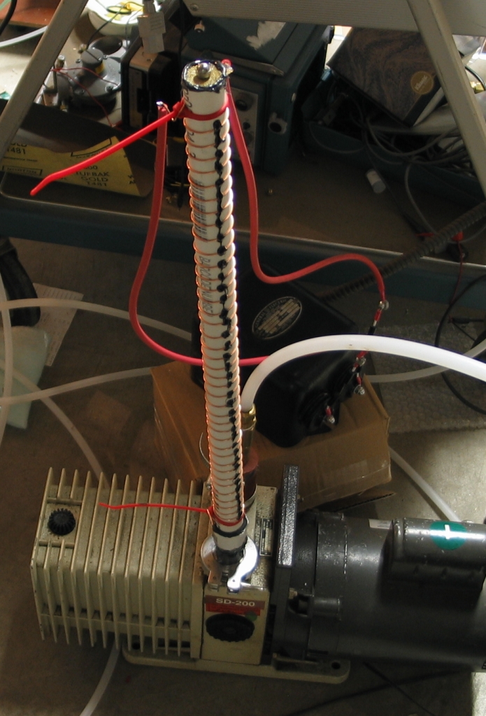
Here is an overview of the Cottrell on the pump, and then
a closer view of the negative terminal:
Net result: Much less aerosol, but if I run the pump
long enough, particularly if I am allowing some gas to
flow through the laser head, I do see some. I
will be looking into ways to improve this, as I need it
to be better than “some”. It is possible
that my HV rectifiers are not up to the task; I will be
testing them when I have time. I am bidding on some
others, which should have sufficient PIV rating to
serve. (I have pairs of 15 kV rectifiers now, and they
may not be stackable...)
(03 September, 2006)
I have rebuilt this precipitator, using about 4 feet
of 1/8" brass rod inside a pyrex tube down the center,
and with a much taller PVC tube on the outside. It
seems to work a bit better. Also, I am running it with
a commercial 20 kV supply, which probably helps.
(Note, added on 27 September, 2006: I did not get the
Cottrell unit to work the way I wanted, and I will
have to revisit it when there is time. I know that
Cottrell precipitators can be made to work quite well,
and I am very curious as to why mine doesn’t.)
(Note, added on 27 September, 2009: Milan Karakas has,
as mentioned above,provided some additional insight, and
I will be rebuilding the precipitator when I have time
and materials. It appears that an uninsulated wire down
the middle of a conductive tube works better than an
insulated wire down the middle of an insulating tube.
This is, in retrospect, not surprising, and we are
wondering why the PDF file referred to above specifies
otherwise. Be that as it may, I have started to build a
new device, which will be about 60 cm tall and will use
3-mil nichrome wire as its corona source.)
...But enough of this. Back to the laser.
I put a strong UV absorber between myself and the laser,
just in case (even though it has not yet shown any sign
of lasing), and examined the discharge. I am getting
bright sparks across the channel, which is both a good
sign and a bad sign. I’m happy that they go across
the channel and not just up to the preionizer; but
I’m unhappy that there are bright sparks rather
than a nice clean discharge. Have to think about what
might govern this and what to do about it.
(some hours later)
What I think is that I need to know just how much vacuum
I am achieving. Without that information, I am floundering
around in the dark.
I cleaned up one of my mechanical vacuum gauges so it
gives sensible readings, and put it on the system.
Couldn’t get any better than about 25" Hg. Went
over the head with Jarrod Kinsey’s stethoscope
method, and found two very small leaks. That bought me
perhaps another inch. It seemed possible that I was
getting some leakage through the wood, so I
fingerpainted RTV on almost all exposed wooden
surfaces. Here is a view of the underside of the
channel:
When I get back from rehearsal this evening, I will
check to see whether I get any better vacuum. If I
can’t get to at least 29" Hg (that’s a
little less than 23 Torr) I am not going to be able to
do a reasonable test, because there will be too much air
in the channel. (For reference, 1 Torr is the amount of
pressure it takes to raise a column of Hg by 1 mm, so
760 Torr, which is one standard atmosphere, amounts to
about 29.92" Hg. Needless to say, if you are in the
middle of a low-pressure zone, and the barometric
pressure is only 28.5", you are not going to pull 29.9"
of vacuum. Likewise if you live at a high altitude. This
kind of thing is why we prefer absolute pressure
measurements.)
In fact, it does:
This is just the beginning, but at least it is
a beginning. I was worried that there might be something
fundamentally wrong with either the design or the build.
Next I get to do some optimization, assuming that I
can get the precipitator to be fully functional.
(mid-morning, 01 September, 2006)
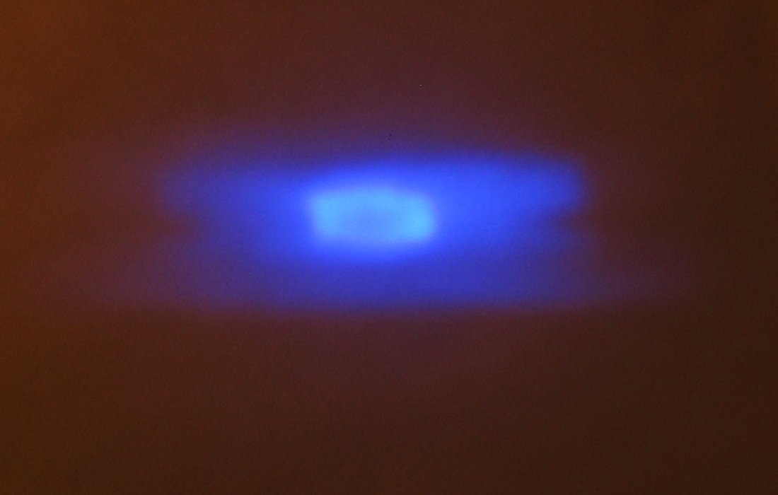
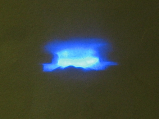
Here are two more photos. The first is the discharge as
it appears with perhaps 75 Torr fill pressure, a mixture
of helium and nitrogen (and some air). The second is the
output. These are both slightly out of focus, and
eventually I will try to take better ones.
The fact that the output looks like a donut is
somewhat unsettling, and I am going to have to
take a good hard look at it. I will also probably
have to put a mirror on one end of the laser, to
see what effect that has. I have acquired a piece
of 3/8" thick glass that will serve as a shelf
for the mirror mount to stand on, and I am
attaching it to the baseplate with RTV. I also
begin to think that it’s time to put a GP-15B
spark gap on this laser, and see what it does at
30 kV.
(03 September, 2006)
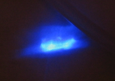
Here is a photo of the output at 20 kV driving the
fluorescence of a piece of bond paper. There is a mirror
at one end of the laser, and the gas pressure is vaguely
optimized. The mirror is quite difficult to adjust, and
may not actually be precisely “on” in this
photo, but it is fairly close. My apologies for the
polyethylene tube that cuts off the top right corner of
the output spot. It is the vacuum hose, and is difficult
to move because it goes to the gauge, which is quite
close to the target.
(Unfortunately, this is cropped straight out of the
original; there is no larger image.)
Small amusement for those who have dealt with high
voltages: because the baseplate is “hot”, I
had to hot-glue plastic bottlecaps onto the adjustment
knobs of the mirror mount, because otherwise I
couldn’t really touch them with the power on. (I
checked and found that even though the mirror mount is
sitting on a glass plate that keeps it insulated from
the base, I drew tiny sparks if I got my fingers within
about 3 mm of any of the knobs, so I decided to be safe
rather than sorry. It pays to be careful with these
devices!)
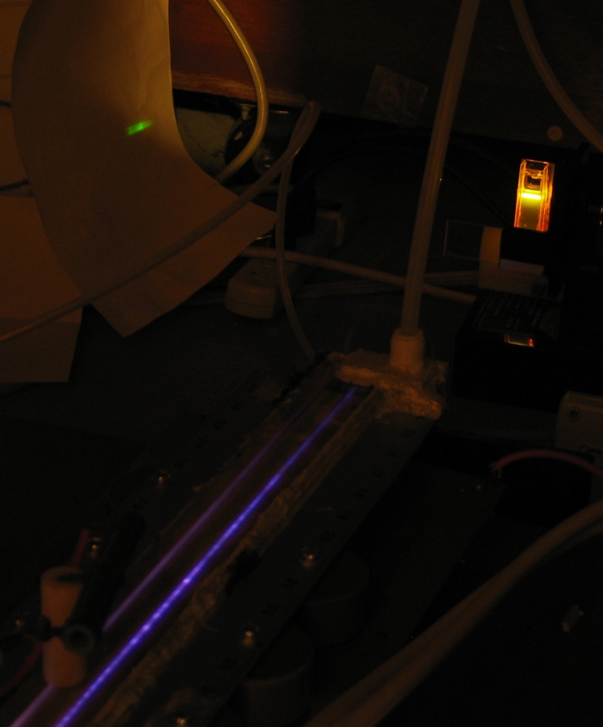
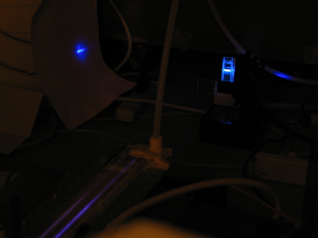
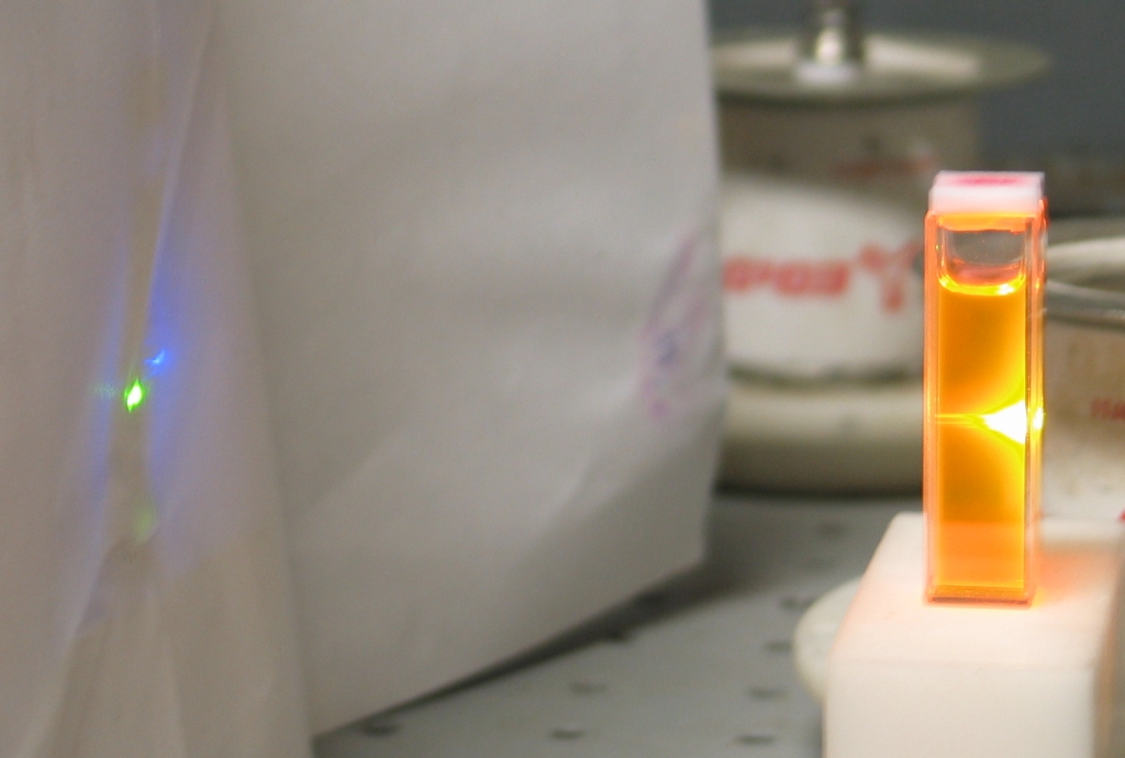
Here is the focused output of this laser, pumping
my homebrew cuvette
to superfluorescence. The dye in the photo on the left
is Rhodamine 6G of rather dubious purity (certainly not
laser grade), and in the photo on the right is
7-Diethylamino-4-Methyl-Coumarin of somewhat better
quality; both are dissolved in 95% ethanol:
The output is the greenish double stripe at the upper
left, on the piece of paper. The first focusing lens is
not readily visible in these photos, but you may be able
to see the second lens, which is cylindrical. In the
photo on the left, the laser is not well optimized. It
had no trouble lasing the dye, however, even with no
external mirrors, and with the walls of the cuvette
deliberately misaligned from the front window so that
they cannot function as mirrors. In the photo on the
right, I have improved the focusing and adjusted the
gas pressure slightly, and the laser is using a larger
spark gap that is connected with considerably broader
pieces of brass shim stock, so it should be switching
slightly faster and possibly producing slightly higher
output power.
(05 September, 2006)
In preparation for running this laser at higher voltages,
I have painted the underside of the head and parts of the
brass shims with HV insulating varnish. When that dries
I will reassemble the laser and try it on the bench,
where I have a larger HV power supply.
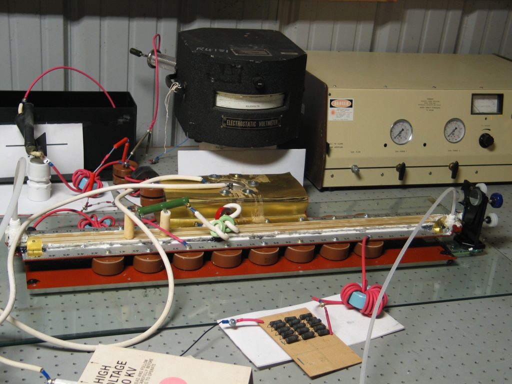
(later, that same day)
Here is the laser on the bench. Directly above and behind
it is the electrostatic voltmeter. You can see part of
the trigger unit in the foreground, and
a commercial TEA nitrogen laser in the right rear.
I have now run the new laser as high as about 28 kV, and
it continues to perform quite well.
Here is something you just don’t get to see every
day — I accidentally got the concentration of dye
in this solution (it’s Rhodamine 6G) a little bit
low, and as you can see in the photo, I am lasing it by
pumping it longitudinally:
If you want to do this deliberately, you will probably
find that it is easier with Fluorescein, which does
not absorb particularly well at 337 nm. (I tested, and
it worked on my first try.) As a start, you may want to
adjust the concentration until essentially all of the
pump light is absorbed in the first 1/4 to 1/2 of the
cuvette; see how things go from there.
It is also possible to lase some kinds of fluorescent
plastic sheet this way, and I once saw some video
footage; but I rarely observe longitudinal pumping in my
own setups, and have not yet succeeded in thresholding
any of the samples of fluorescent plastic sheet I
have. Perhaps as I get this laser better optimized I
will try again.
(05 September, 2006)
Pulsing the laser once per second, focusing the beam
into a Scientech head, and running the output through a
x100 instrumentation amplifier, I get a reading that
corresponds to about 0.67 milliwatts. That’s
roughly 670 microjoules per pulse. I am hoping that I
will eventually get considerably more out of this laser,
but it will take additional optimization, possibly
including finding and fixing more leaks.
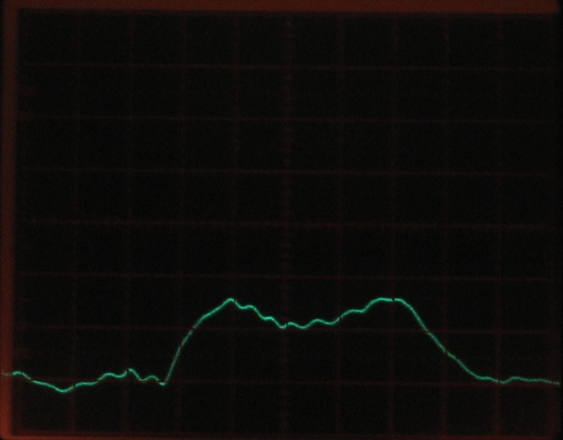
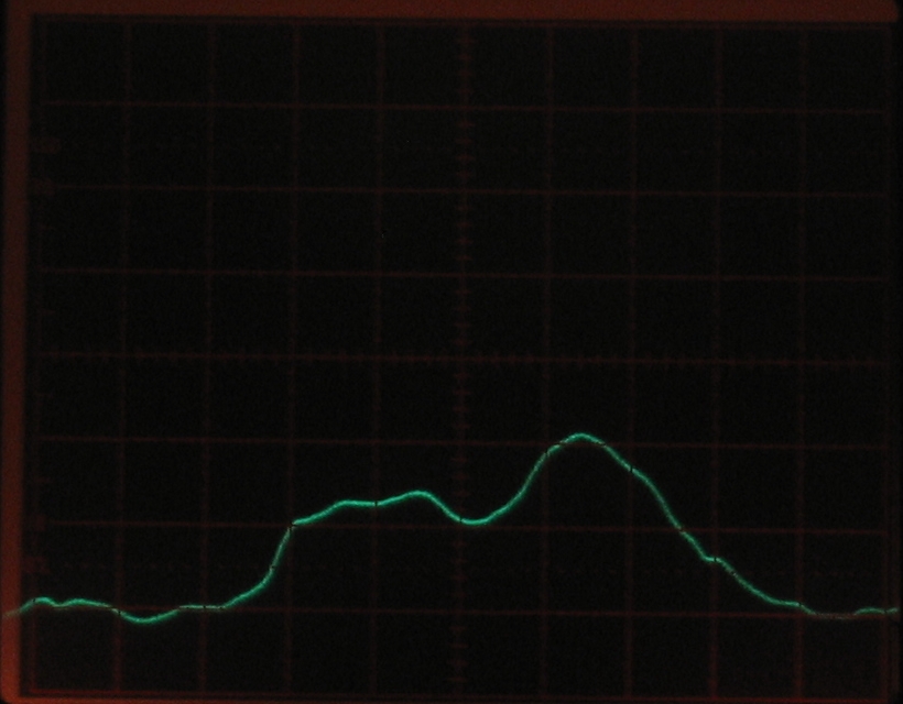
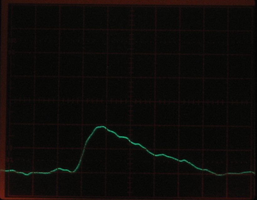
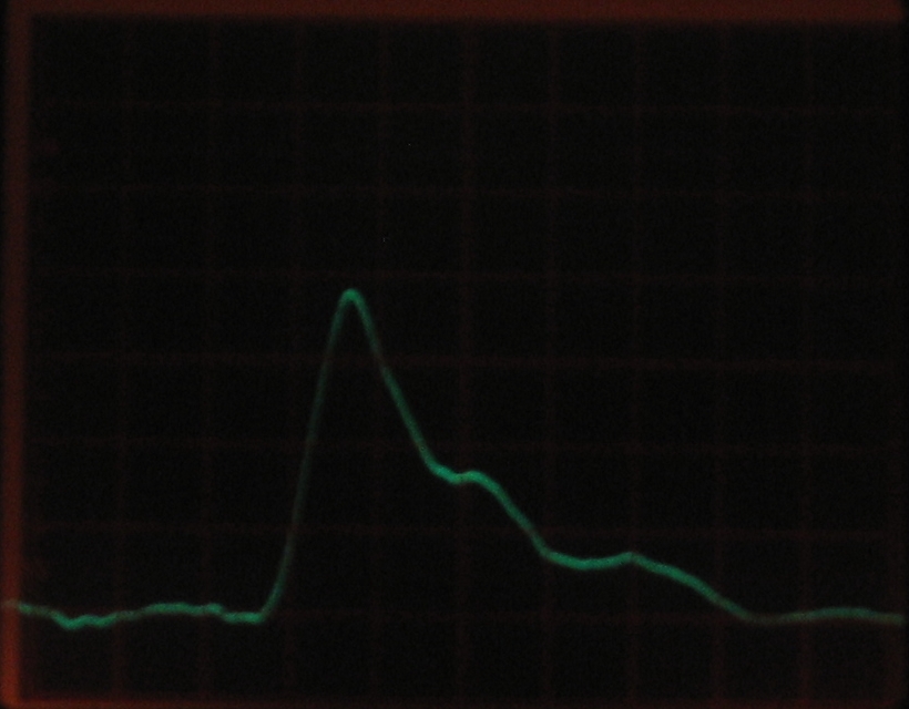
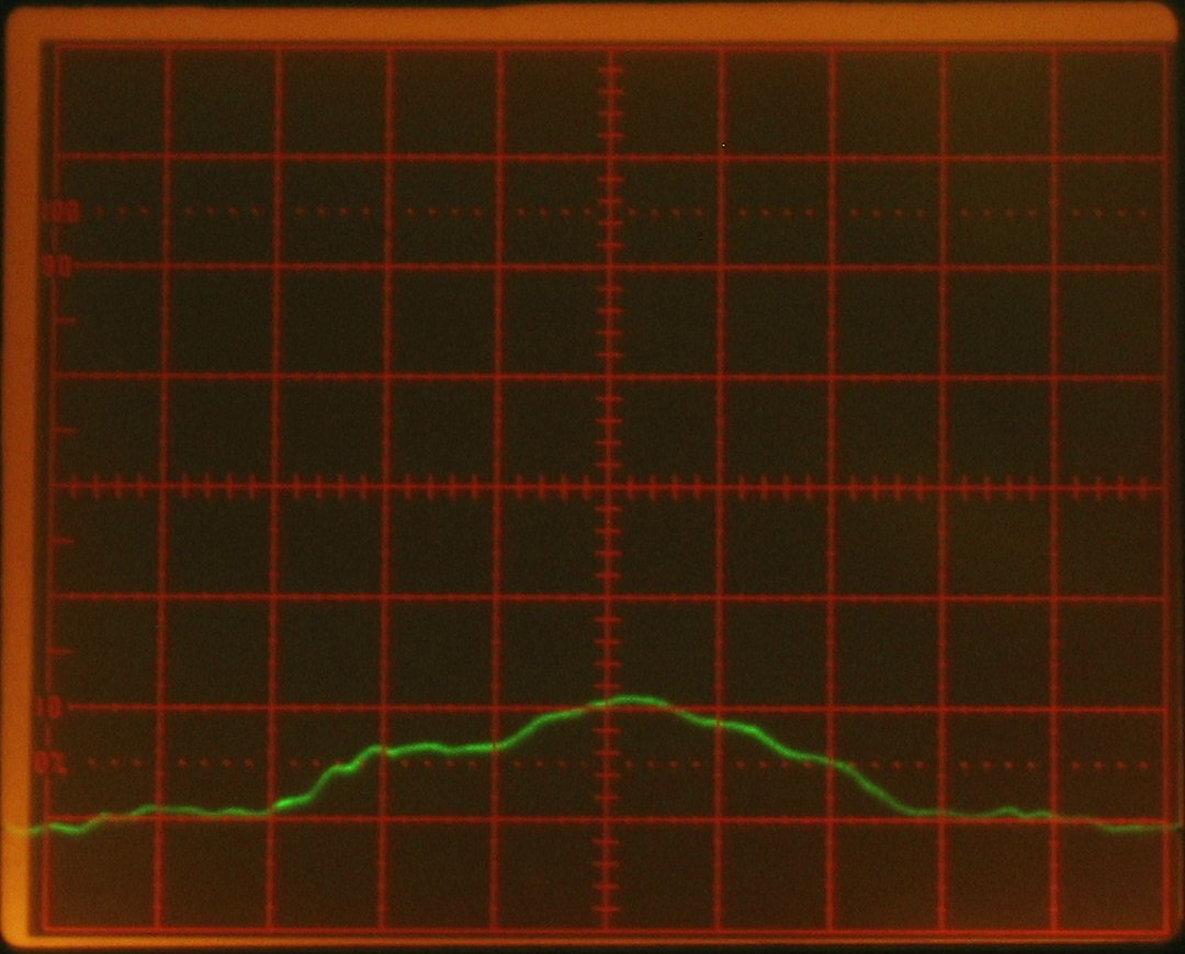
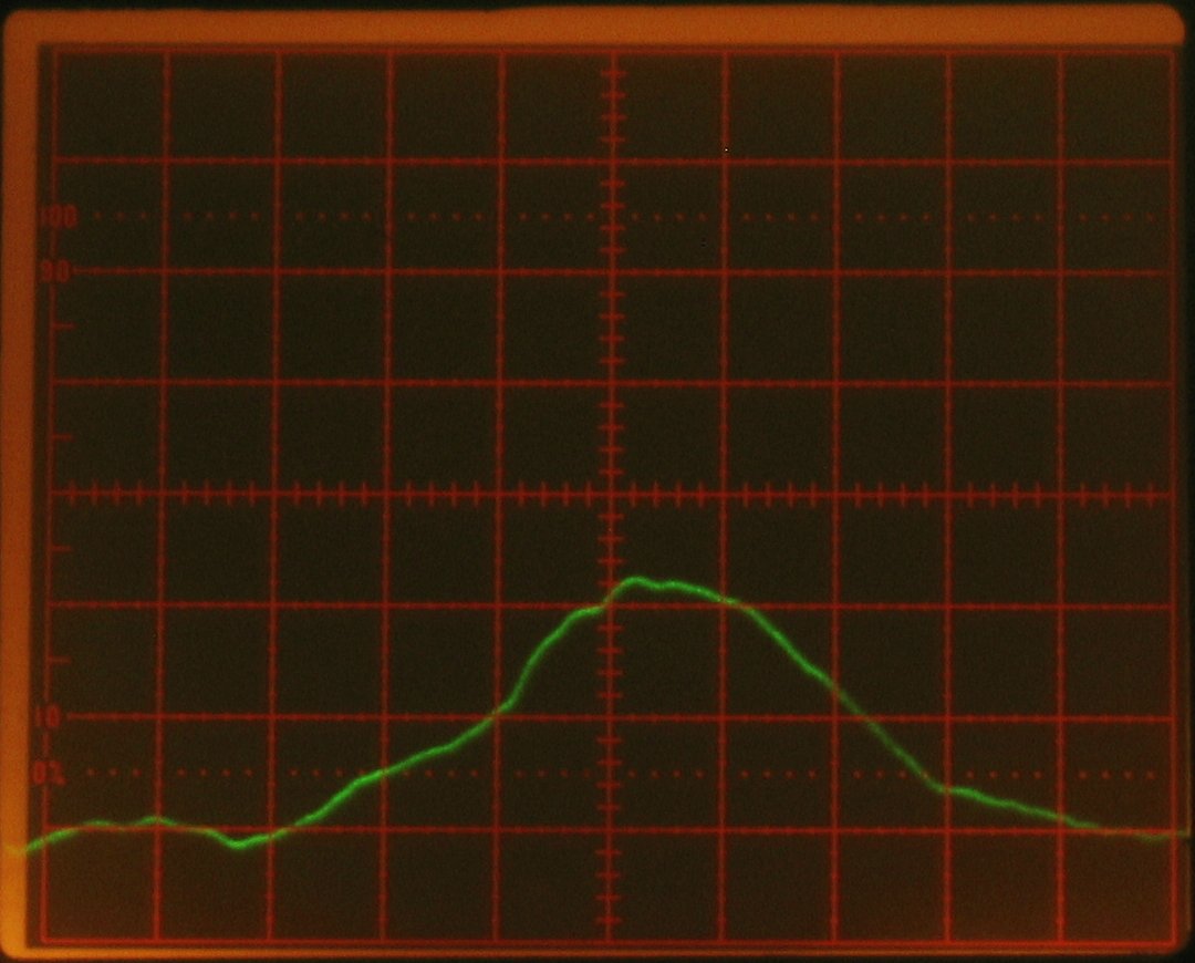
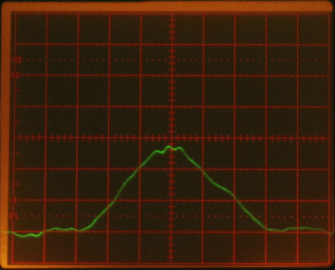
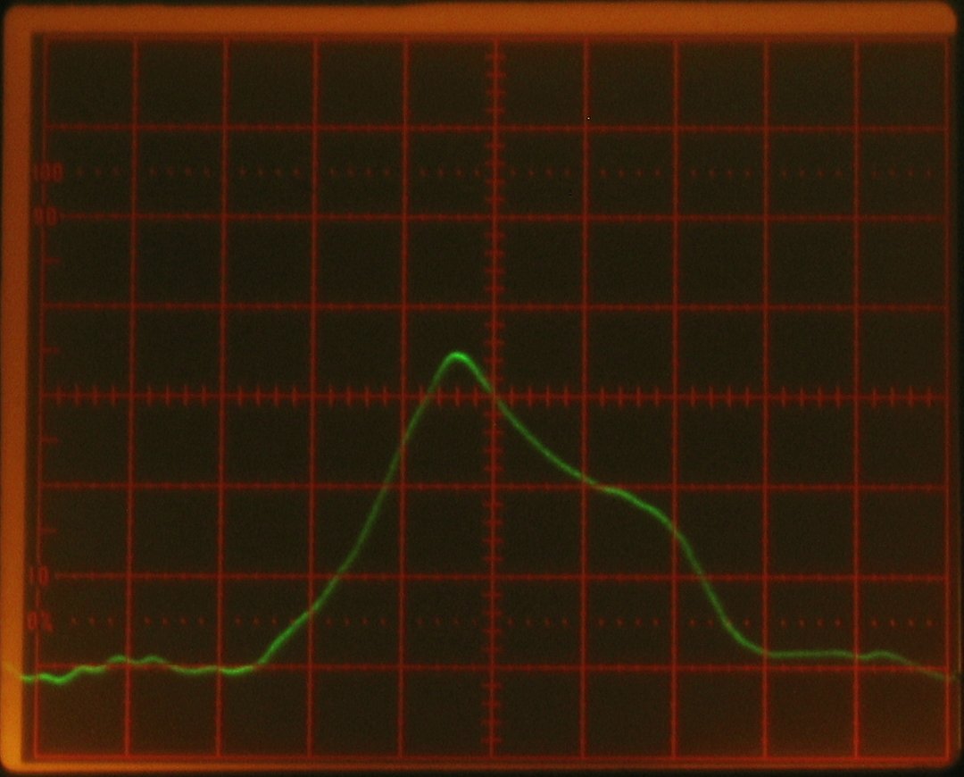
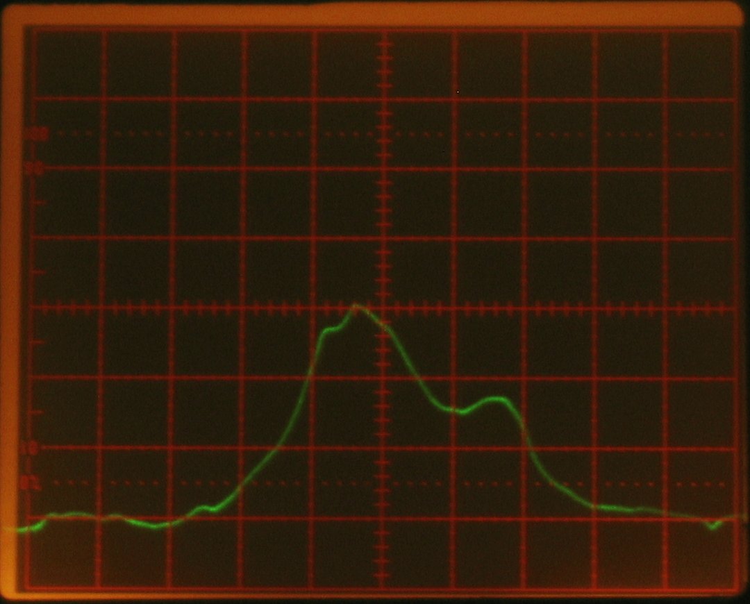
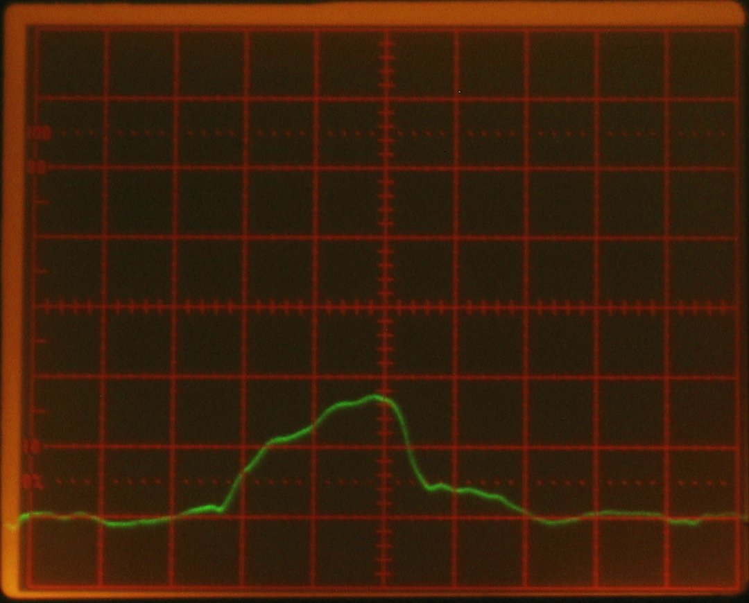
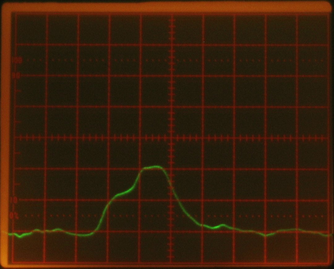
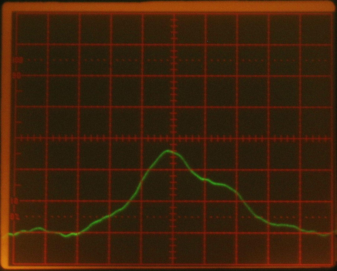
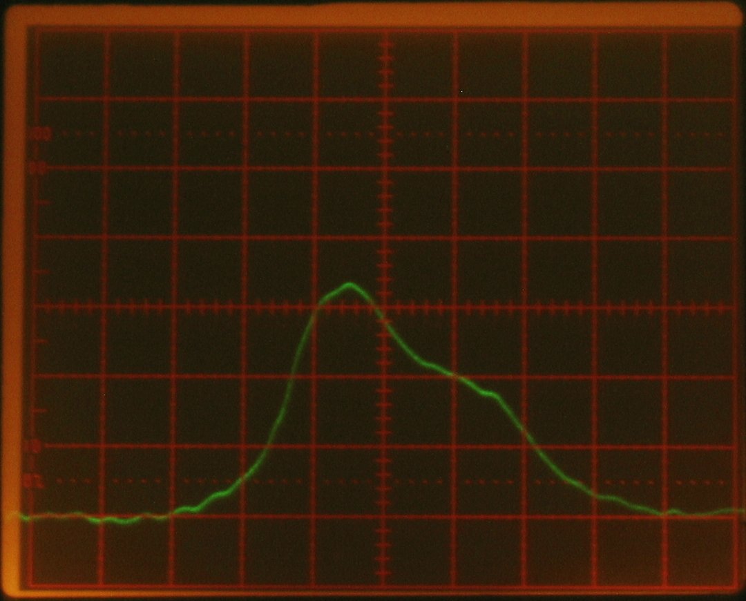
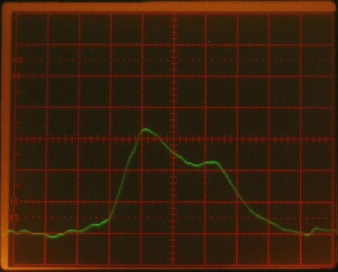
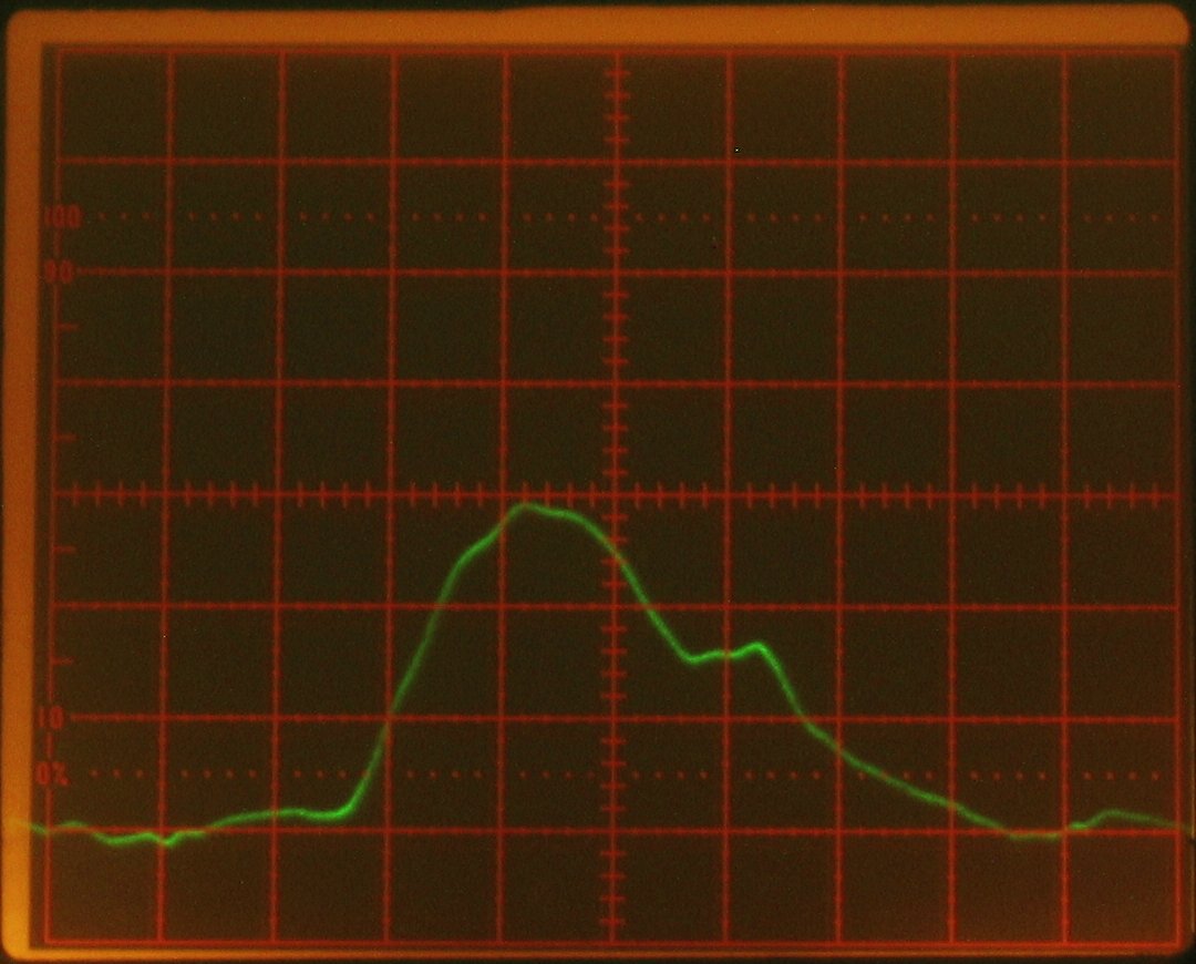
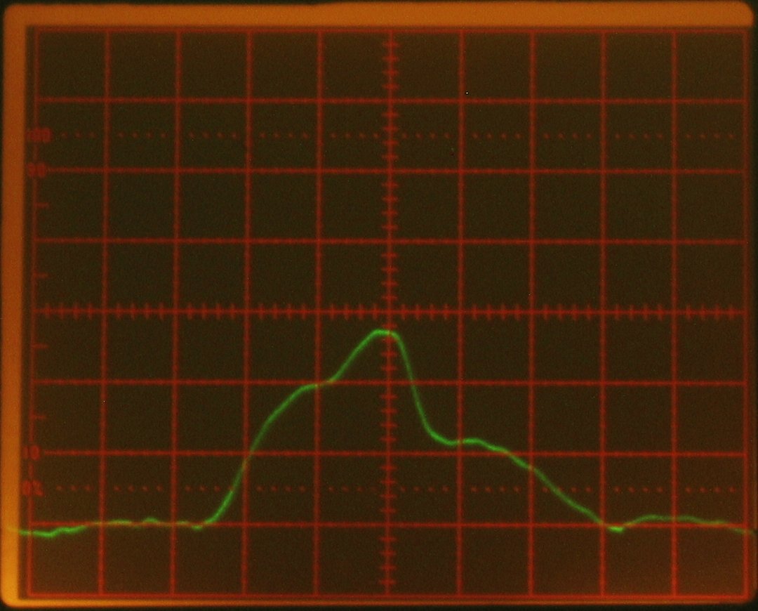
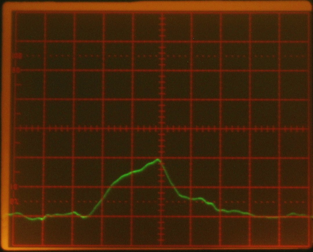
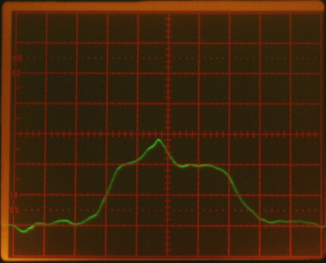
Here are four representative output pulses. These were
taken at 25-27 kV (the last one is around 27, but I am
not entirely sure about the others). The last one also
shows what happens when I tweak the gas pressure. It is
a little better than most, but still fairly
representative. (My apologies about the blur. The
camera seems to have some doubts about how to focus.)
These are at 2 nsec per division on the screen. The
sensor is a Motorola MRD500 photodiode, with bias
provided by 6x 9V batteries in series, for ~54 VDC. The
signal from the diode goes down a piece of 50-ohm
coaxial cable that is about 8" long, directly into the
input of a 7A19 vertical amplifier (600 MHz bandwidth)
in a Tektronix 7104 mainframe (1 GHz bandwidth). The
risetime of this setup should be 1 nsec or a bit less,
and is most likely limited by the photodiode.
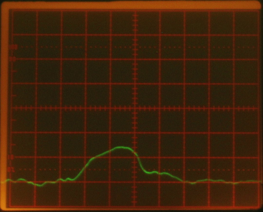
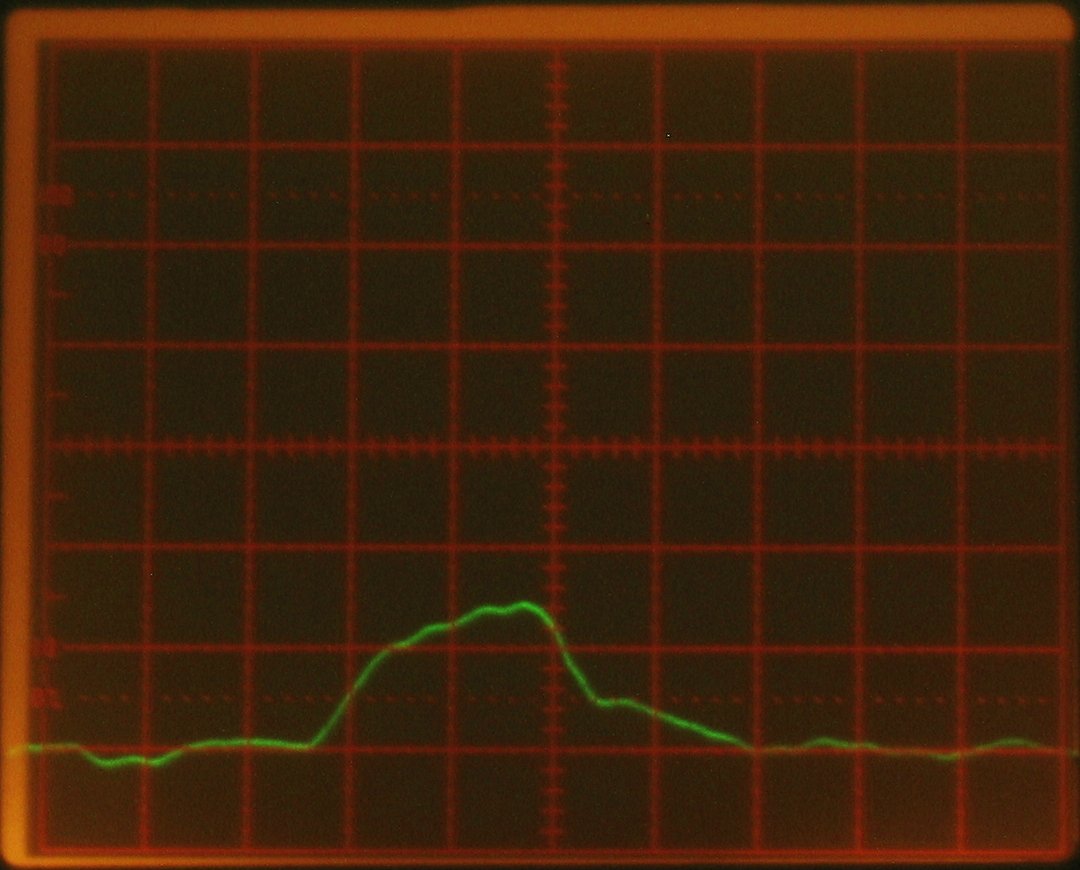
Please notice that the FWHM pulsewidth here is 9-10 nsec
in the first two photos; 6 or 7 in the third photo (it
kinda hangs at the 50% mark for a while before finally
dropping); and 4 nsec in the last photo, largely because
of the tall first peak. The peak power of the pulse in
the last photo is much higher than the peak power in any
of the others, but I suspect that the pulse energy is
largest in the second photo. The fill gas for all of
these, btw, was just nitrogen (except for any air that
got in through leaks). I have not yet tried examining
the pulse with nitrogen and helium together.
Here, just because it happened, is the result of putting
too much energy into the photodiode. This was at 10 nsec
per box...
I knew it couldn’t really be an accurate record of
the laser’s output, but when I blocked the light I
didn’t get a trace, so it was clearly a real
signal, and it was coming from the photodiode. Took me a
little while to figure out what was going on. I then put
a piece of 1/4" window glass and some fluorescent
plastic in front of the laser, which absorbed enough of
the beam that the diode could handle what remained. I
found, btw, that I had to choose carefully. Even a 1-mm
thickness of the plastic that appears to be doped with
Rhodamine B absorbs essentially all of the nitrogen
laser’s output. (The plastic did not lase, partly
because the output of the nitrogen laser was not focused.
I will probably be trying again at some point.)
(evening of 06 September, 2006)
After dinner, I optimized the pressure by watching the
scope as I fired the laser. With the current mix of
nitrogen and helium, the traces were tallest and
probably widest at 25.2". (I should note that I do not
have gas flow meters, so I don’t really know
what the precise mix is.) I then put the power meter
head in front of the laser, and measured the energy.
This turns out to be, very roughly, 1.2 millijoule per
pulse. Given a pulsewidth of about 8 nsec FWHM, which
may actually be a bit on the long side — see
photos, below — we are looking at peak power on the
order of 150 kW. (The 10-10 pulsewidth is considerably
longer, and the average power is only perhaps 100 kW.)
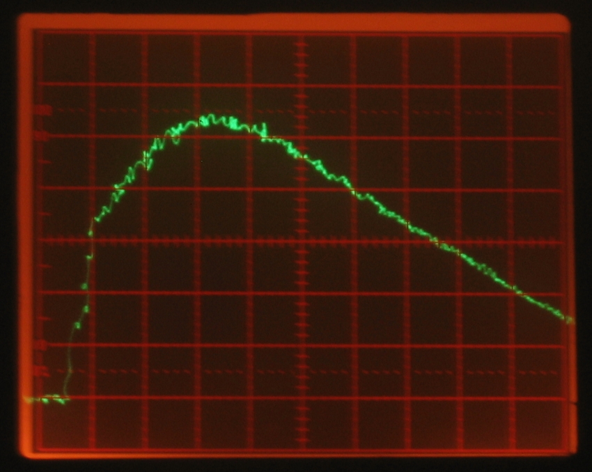
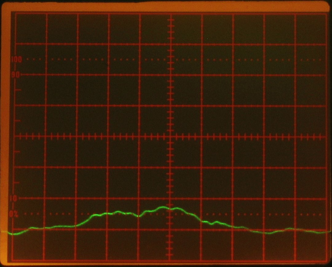
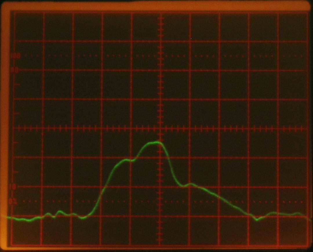
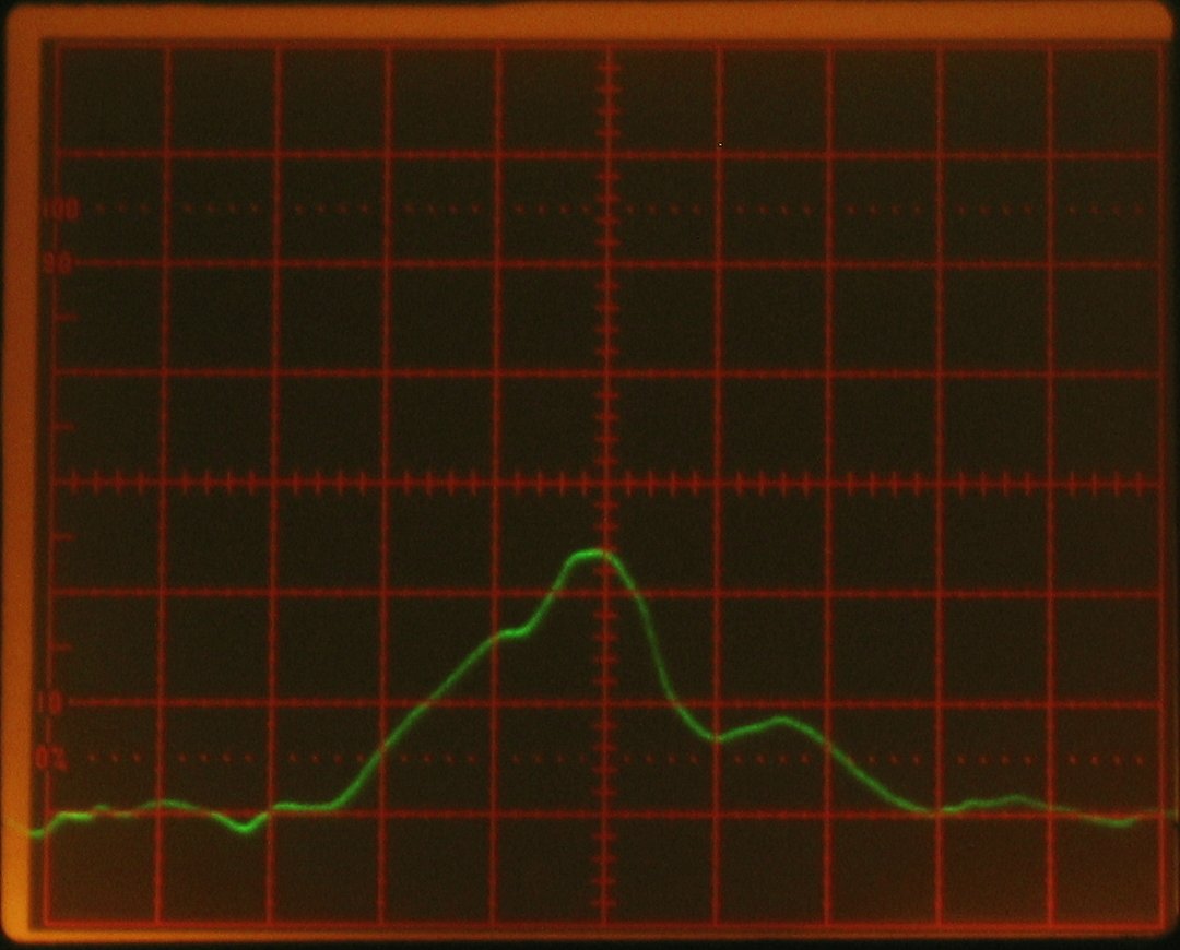
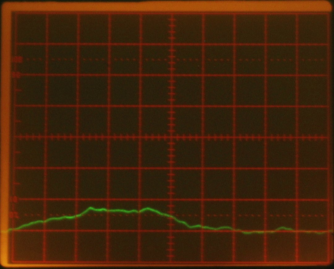
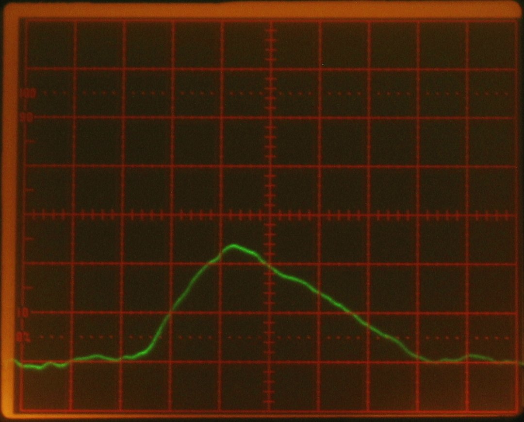
Unfortunately, I did not get a picture of the optimized
trace; but I have other traces here, taken at various
pressures that I have labelled on the small images.
Notice that with both gas mixtures shown here, I am
getting best operation around 26.5 to 27.5" of vacuum;
I don’t know how to reconcile that with the 25.2"
that I was getting earlier, though that mixture may have
had a significantly different ratio of helium to
nitrogen.
[Note: if you click any of these, you’ll get a
1080x870 px enlargement. That larger image is a
direct crop from my original, and is the largest size
I have. The traces, btw, should be easier to see on
the enlargements; they did not show up well, so I
tweaked the green levels to make them more apparent.))
There is considerable variation in the pulse shape
(and the height) from shot to shot, as you can tell
by the fact that the 24" trace with nitrogen and
helium is slightly higher than the 24.5" trace.
Notice that there is clear evidence of a double peak in
some of the traces, particularly around 27 to 26".
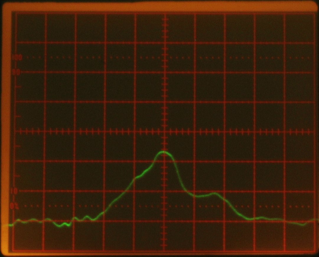
You can compare those with these two pulses, showing
the two gas mixes at the same pressure:
Another thing that I am beginning to observe (but have
not yet had a chance to photograph) is that if I pulse
the laser and then pulse it again a little less than a
second later, the peak at the beginning of the second
pulse is generally a lot stronger. In fact, if I start
with a good first pulse at 27 or 27.5", the peak of the
second pulse is usually off the top of the screen. It is
very likely that this indicates inadequate preionization,
and I may decide to grit my teeth, rip the roof off the
head, and bring it back down to its original height. I
dread the process of finding and fixing the leaks, but I
really want to know...
(08 September, 2006)
I took off the lid and tried to remove the added spacers.
This failed, so I built another lid. The main spacers are
3/16" thick, and the preionizer is on a piece of spruce
that is 1/8" thick, so it is back to its original location,
1/16" above the height of the electrodes.
The preionizer is warped, but it seems to be of uniform
width, so the total gap is about the same all along even
if one side is wider than the other. I am seeing some
bright sparks, and I was prepared to build yet another
roof for this head if necessary, but the device is
definitely a laser — I have already used it to pump
and tune some R6G. When I get a chance, I will make some
measurements on it, but first I want to find and fix any
leaks I can. Even moderate quantities of air are bad for
performance, and I can tell that I have to let a little
more gas into the head now, before I see lasing. I’d
like to get it at least as vacuum-tight as it was earlier.
(some time later)
I decided, after measuring less than 900 μjoules
per pulse, that this roof was less than satisfactory.
After some thought I decide to cover the entire
underside of the next roof with SiC, which meant that
I’d be unable to see the discharge in any case,
so I made a new roof out of wood. Here’s a view
of the “carborundum carpet” on the
“ceiling”:
Reasonably nice smooth coating of carborundum, 7/8"
wide. Sorry the photo is slightly blurry.
(afternoon of 09 September, 2006)
I have found three smallish (but clearly significant)
leaks, and applied RTV to them. Tomorrow morning when I
get up (or around 2 am, if I’m still awake), when
the RTV on the third one is reasonably firm, I will
check again to see how well the head holds vacuum. So
far, I am not seeing very much change as I find and
fill these things; but they have all been right near
the vacuum port, so that isn’t too surprising.
(afternoon of 10 September, 2006)
It was essentially impossible to fix the leaks, partly
because I had not clamped the roof onto the head when
I attached it, and the weights I used were not heavy
enough; the new roof is slightly warped, and it sits
a wee bit up in the air ...until I pump on it. The
motion was reopening the leaks, so I finally gave up,
removed and reglued the vacuum port, and started the
de-leaking process again this morning.
That went well, so I fingerpainted RTV over almost all
of the exposed wood on the top. I just measured about
230 kW output, and that’s with a small amount of
the beam obscured by some RTV on the inside of one of
the windows. (See photos, below.)
(NOTE, added much later: the paintable RTV that I used
for this seems to be the wrong type. If you must seal
anything with silicone caulking, the kind that smells
like vinegar as it cures is probably a better bet.)
There is a distinct problem about this: the RTV should
not actually be in the beam path. The beam is shaped
like one or two curved lines (depending on pressure and
voltage), and I am convinced that this is because the
faces of the electrodes still have the anodizing on
them, so the discharge actually goes from upper edge to
upper edge and from lower edge to lower edge. I have
acquired a small diamond grindstone at the hardware
store, and the next time I take the roof off this laser,
I will attempt to get the anodizing off the electrode
faces with it. That may not help, btw. If it increases
the volume of the discharge too much, the laser may not
be able to pump the gas as well, which would actually
reduce the output. Mind you, I doubt that this will turn
out to be the case, but it is definitely a possibility.
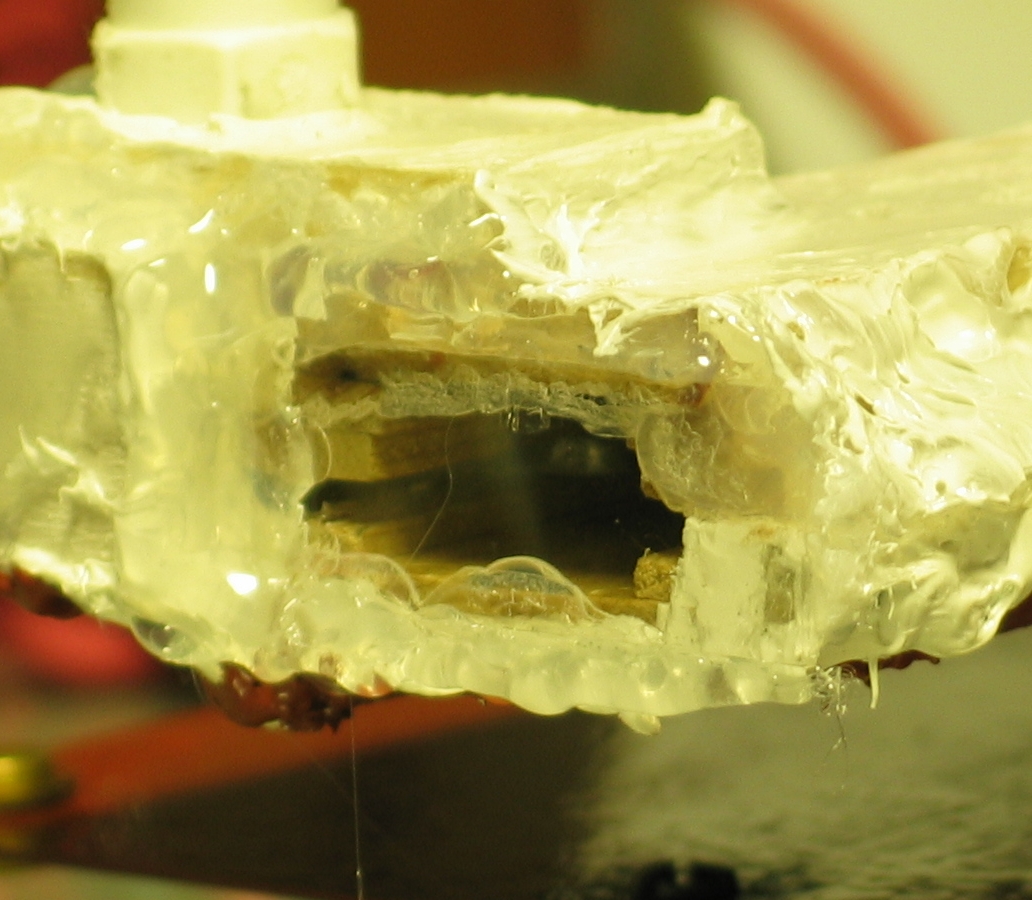
Here is a look at the window, so you can see the RTV,
and then a look at the output. Unfortunately, I had
the camera a bit far away from the target, so the
512x384 enlargement is as big as I have right now.
You can see the mountain shape all too clearly on the
target. As I say, if I take off the roof again I will
remove the excess RTV, but I hope it won’t
actually be necessary.
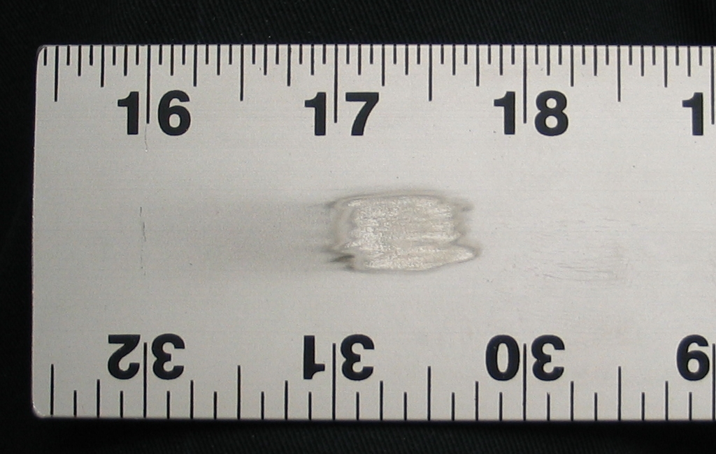
If I have measured the power correctly, it should be
possible to create a spark on a metal surface by
focusing the beam. I will be trying that this evening,
and will attempt to photograph it if I can do it.
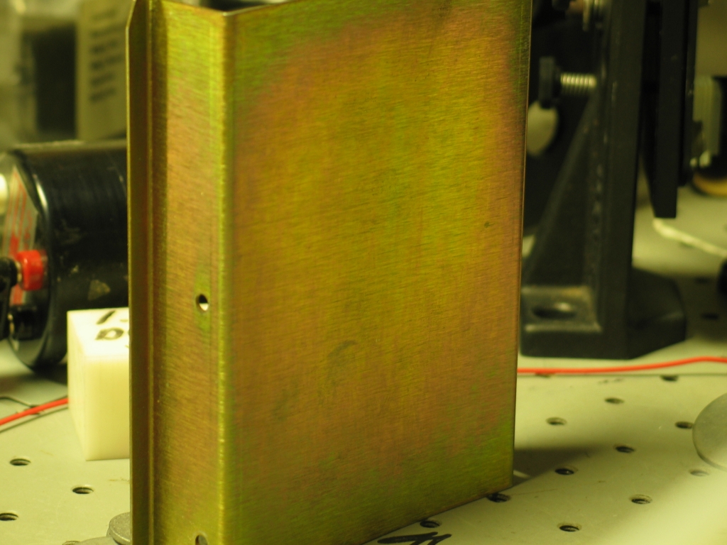
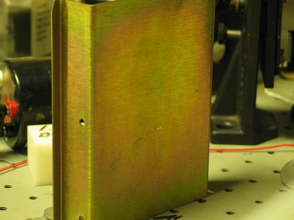
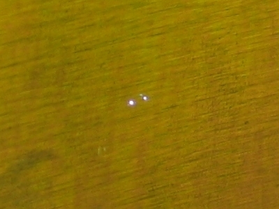
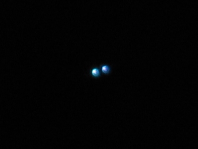
...And, in fact, it is possible. Here’s
the target, the target with a spark, and then tight
crops, one from the second photo and another (even more
out of focus, alas) that I took with the room lights out.
I have removed the RTV from the inside of the window,
and attempted to remove the anodizing from the edges of
the electrodes, with indifferent success. The head is
now reassembled and the RTV is setting, so I won’t
be able to do any further testing for nearly 24 hours.
Such is life; when there is any news worth reporting
(for example, output of significantly more than 250 kW,
or if I find that I can pump a dye laser with the
unfocused beam), I’ll report it, probably with
photos.
(evening of 11 September, 2006)
The de-leaking process continues. I have eliminated
several fairly gross holes, the latest one only a short
time ago, so the RTV on it is still wet. I should be
able to resume leak-testing some time tomorrow.
In the meanwhile, I should note that I will be
constructing a new head for this laser. It will have a
channel about 25 mm (roughly an inch) across, so I can
see whether that works better than the relatively tight
spacing (about 16 mm, roughly 5/8") of the current head.
The initial preionization method will be essentially
the same — a “carborundum carpet” on
the ceiling, this time just over an inch across, and
again 1/4" up.
I bought two painted rulers today, in the hope that they
are not anodized, as paint is going to be a lot easier
to remove from the working edges. They are now cut down
to 35" length, just a bit longer than the ones in the
first head. This means I have to position the mounting
holes slightly differently, by 1/4", but that’s
easy enough.
(27 September, 2006)
I built the new head with 1" channel spacing, which was
probably a bit large for this laser. Nonetheless, it
put out almost 240 kW. At that point I decided to return
to the charge-transfer laser on the third page of this
series (005b1.html), to find out whether I can coax better
performance from it. I am also working up the “How
to Build This Device” page. (See links, below.)
(27 September, 2009)
I need a nitrogen laser for one of my projects. Because
I have disassembled the one I’m currently working
on so I can do a major rebuild of its head, which is
complicated and will take considerable time and effort,
I decided to reconstruct this one. In the process of
doing so I have been having a very difficult time
“de-leaking” the head, which prompts both
the addendum about wood porosity above, and this second
addendum.
Note: in addition to the porosity issue, it appears that
the plastic fittings that I used in the initial version
are not really suitable for use in vacuum systems. They
perform nicely with pressure in them, but under vacuum
they allow too much air into the head unless, perhaps,
you operate with a large amount of helium in the gas
mixture. For this rebuild I have substituted ordinary
brass compression fittings, but with one difference:
instead of the brass compression rings that came with
the fittings or delrin rings (available at the hardware
store), I am using pairs of small o-rings. This allows
me to tighten the nuts by hand if I am careful.
I’m not sure whether Delrin rings would permit you
to tighten the nuts by hand, but they may be viable
[with a wrench] if you can’t find appropriate
o-rings.
The rings I’m using are 1/16" thickness, and have
inside diameter just a bit smaller than the
polypropylene or polyethylene tubing that I’m
using for gas and vacuum, so I have to stretch them a
little to get them on. I use them in pairs because a
single ring does not provide an adequate seal; the nut
goes all the way onto the fitting without compressing
the ring. That is, the second ring is just a spacer, and
you could substitute something else for it if you
wanted; but it seems simpler just to buy them in pairs.
(02 October, 2009)
Meanwhile, I have found about as many leaks as I can by
just dipping the ends of the head into water, and I have
built a trough that should allow me to dip the entire
head. When all of the caulk sets, I will give it a try.
(05 October, 2009, evening)
Having completed the trough I dipped the head into it,
and discovered that in addition to a very small leak at
one end and a somewhat larger leak at the other end,
there were various leaks along the upper sidewall. I
originally attempted to seal this sidewall with RTV, but
as I mention above I used a type that can be painted.
This turns out to be a mistake, and I cannot recommend
it. In fact, I strongly suspect that RTV is not a truly
optimal sealant for large areas of wood, and may not be
a particularly good sealant for wood in general.
Last night I sealed two more wooden yardsticks with
thinned epoxy, with the thought that I would use them to
replace the sidewalls on the existing head. As of this
afternoon, however, I have decided to put that effort on
hold and make a new head first, using plastic sidewalls
instead of wooden ones. (See
the follow-on page
for details.)
Citations for some interesting papers about nitrogen and other lasers...
To the first page in this set, a general discussion
of the issues involved in designing and building a
high-performance nitrogen laser
To a page about my initial effort to produce a
high-performance nitrogen laser
To a page about my continuation of that effort,
which resulted in a laser that puts out about 100 kW and
can operate without a vacuum pump
To a “How-To” page about that laser
To an interim page about my effort to scale up a published design
in order to enhance its performance
To the next page about this laser
To a page about my current (late 2006) effort to build
a less-expensive laser with even better performance
To the Joss Research Institute Website
To my current research homepage
My email address is a@b.com, where a is my first name
(jon, only 3 letters, no “h”), and b is joss.
My phone number is +1 240 604 4495.
Last modified: Wed May 10 14:54:38 EDT 2017
Yet Another ReDesign (YARD)
Sidebar: Preionization Techniques
The Build Continues
![]()
Sidebar: Capacitor Improvement 101
Interlude: Vacuum
Possible Method #1: The Cottrell Precipitator
Power and Energy Measurements
First set, nitrogen and helium:
Second set, just nitrogen:


Rework, September-November, 2009:
References
This work was supported by
the Joss Research Institute
Contact Information: