(22 June, 2005)
Having spent the weekend at a conference on European Cooking from Rome to the Renaissance, I return to these issues refreshed and burping contentedly. (Actually, there was very little I could eat; but it all smelled nice, and I learned quite a bit.)
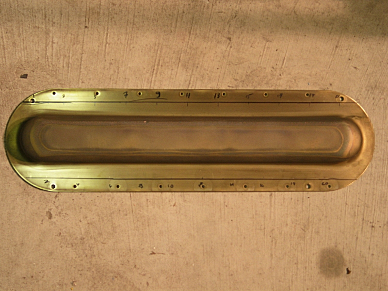
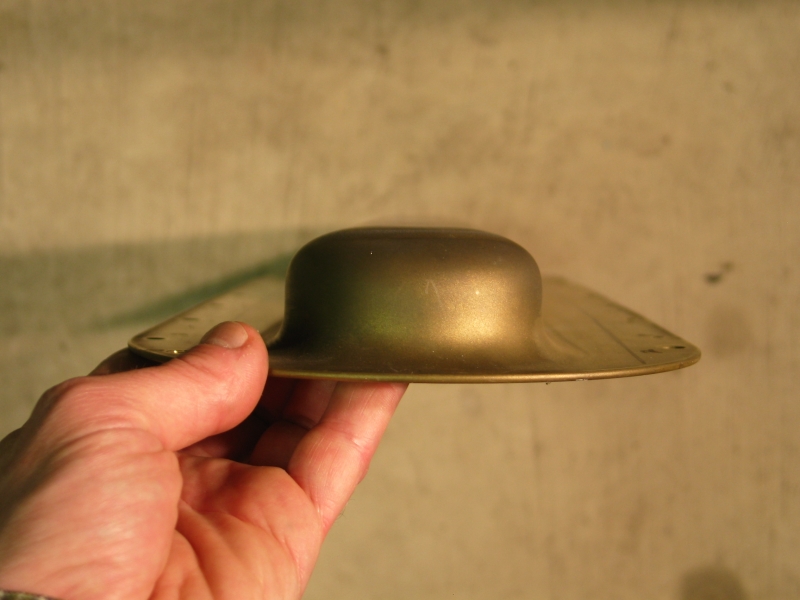
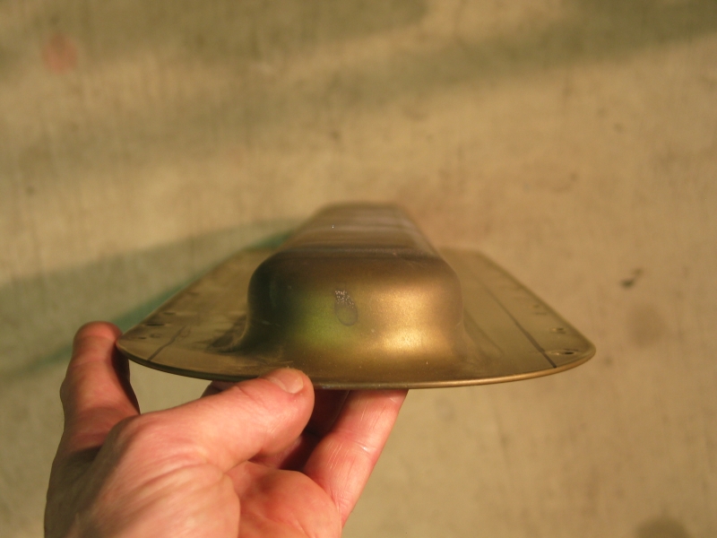
A long time ago, Doug (founder of the Joss Research Institute) handed me what looked like an excimer laser head, made of two pressed brass electrodes, with pairs of doorknobs down the sides. It was pin-gap preionized, but oddly: the electrode profiles are very tall, and the pingaps were between the doorknobs of a pair. (I’ve already taken it apart, and I’m not finding the picture I thought I had, but perhaps I can take some photos of the parts. If so, I’ll post them here.)
(If you want the full pixels for the first one, drop the “u” from the number in addition to changing “8c” to “22c” in the filename, but be prepared for blurriness. For some reason, the camera failed to focus correctly.)
Because I appear to have failed to reach threshold with the CO2 head, and because I’m reluctant to rip it apart further, I’ve been thinking about using one of these electrodes and some 900-pf doorknob caps to try out my metal-mesh-cathode idea.
I went to the hardware store yesterday to look over the possibilities. They have metal mesh, thin aluminum; but the holes are not exactly in the optimal pattern, and I failed to find a 1-x-2-foot sheet in plain metal — all they had were painted ones. I only want a strip about 5" wide, so it seems like a waste to buy the larger size, the more so considering the fact that even the little sheets are $14 or $15 apiece.
...So I went up on the Web and looked at various things. I find a few that could serve, and they don’t appear to be too hijjusly pricy. (In other words, this approach may yet be viable.) OTOH, my doorknob caps are only a little over an inch tall, which means that the anode-to-cathode spacing would be very small if I were to use one of these electrodes. This worries me.
While I was at the store, I noticed a number of other items that I found intriguing. One was a T-shaped molding with a gently rounded top. It occurs to me that I could remove the vertical bar of the “T”, and use the resulting shape to hold some shim stock in a nice curved shape. That would make an anode of much lower height. I’ve also found some “half-oval” brass bar on the Web, which I could use as-is. This would eliminate the whole height issue.
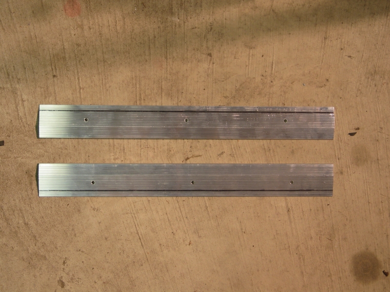
Another thing I saw is some aluminum extrusion that is intended to protect the front edge of a stair tread. That set me off on an entirely different tack: it’s just about perfect for a simple voltage-doubler laser. Here’s a lousy diagram:
             o + Trig
             |
        +---   ---+------+------       -------+------- + HV
         |       |     -----    \     /     -----
         | SPARK |    |  3x |    |   |     |  3x |
         |  GAP  |    |2.7nf|    |   |     |2.7nf|
         |       |    |     |   /     \    |     |
         |       |     -----                -----
        +---------+------+--------------------+------- GND
I’ve omitted several things, including the box around the laser channel, which there wasn’t really room for. Also, I couldn’t draw the edges of the extrusion correctly; they are actually nicely rounded.
I have some reservations about this, but it may be worth a try, ...if it won’t just arc down the hose to the helium tank when I turn on the 20 kV power supply. (One possible way around this is to run the top at ground potential, and reconfigure the power supply to be negative-hot. I’d have to sit the laser on a massive insulator, but that turns out to be quite easy: I have a nice sheet of FRP that I can use.)
Yes, I know, I said I wasn’t going to do a voltage-doubler circuit; but the pieces are readily available, and who am I to blow against the wind? Also, you will note that I’ve listed only 3 caps on each side (changed to 5 for the next design). This is a “baby steps” machine, to see whether the general idea is viable. It should let me test semiconductor preionization, and if that fails I can easily go to DC preionization. Moreover, I can build it on a full-length base, so that if it works well I can easily rebuild it with 10 caps per side. (Not that it matters — the plastic box around the laser channel is probably the most difficult part of the thing, and that would have to be replaced in any event.)
For the moment, I’m still thinking. This idea, however, is very attractive, partly because it should be easier to construct than any of the others, and I may just grit my teeth and build it. Should be an interesting test-bed, if nothing else.
As usual, I’ll post more as there’s more to post...
(Later That Same Day, Or Actually Early The Next)
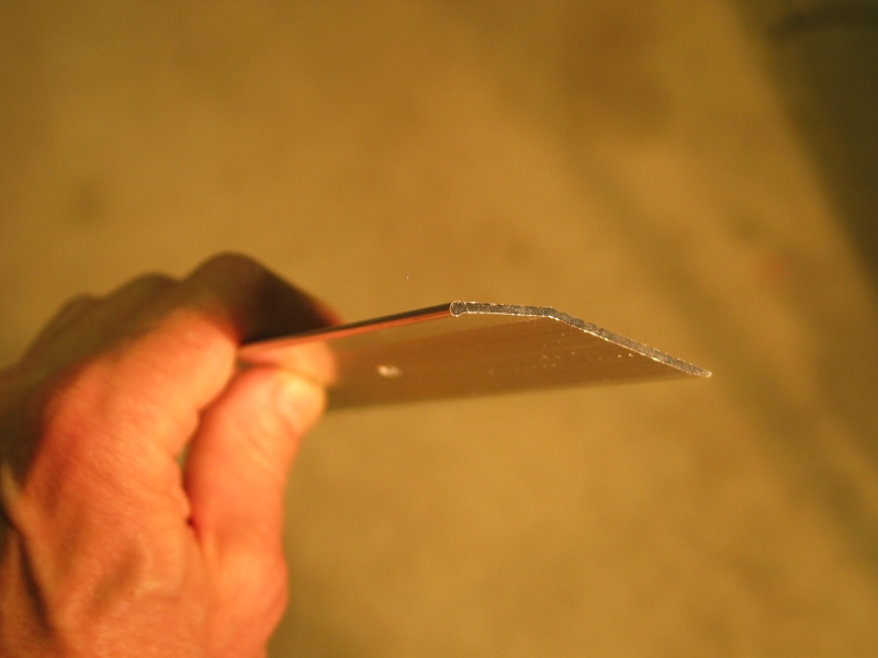
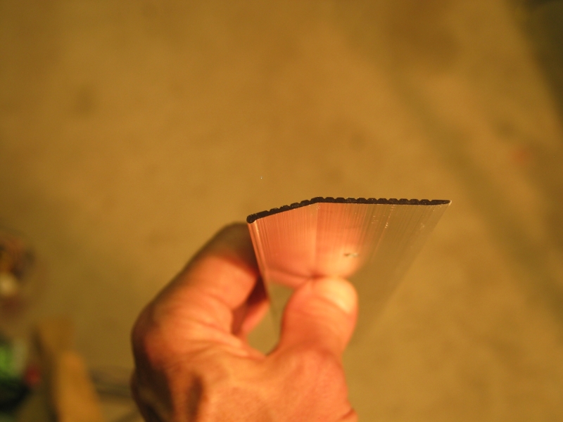
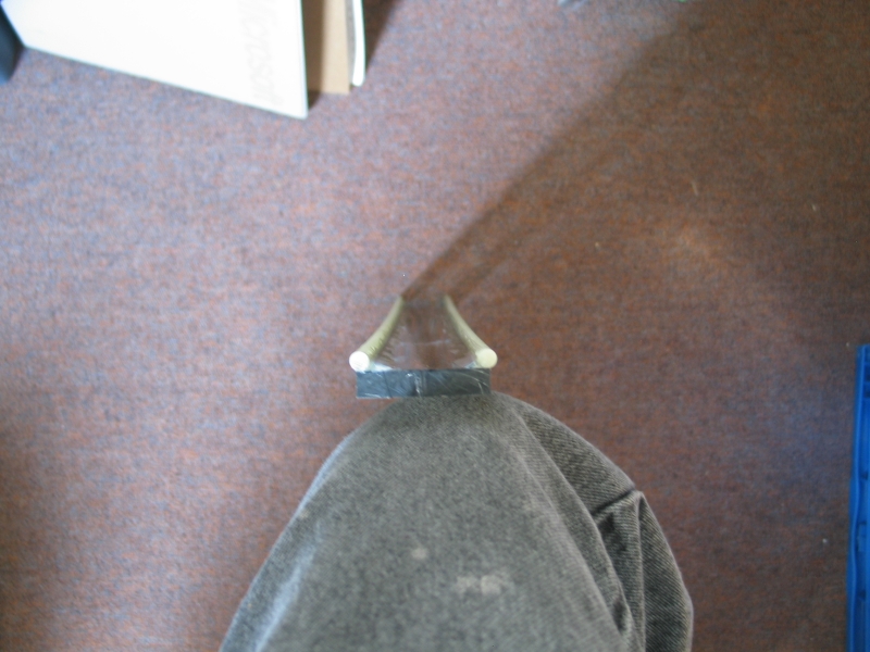
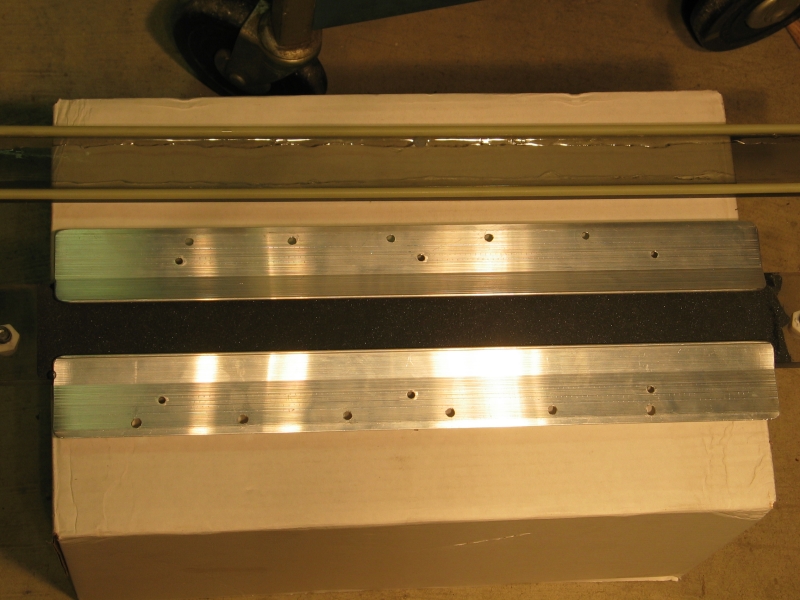
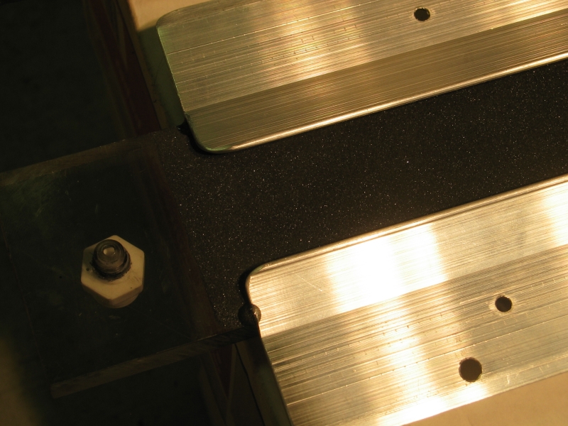
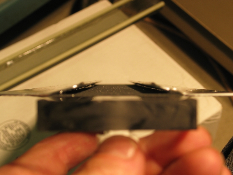
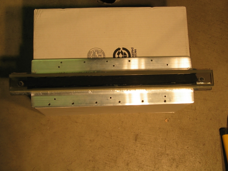
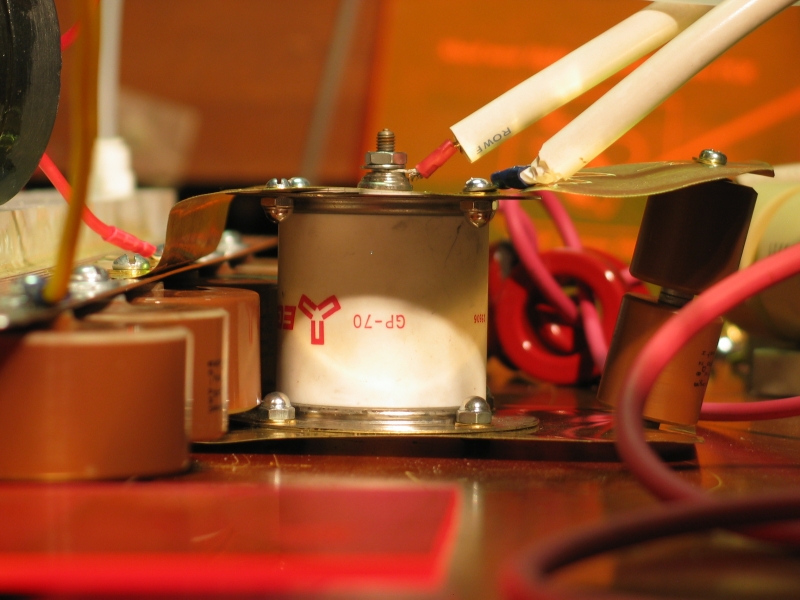
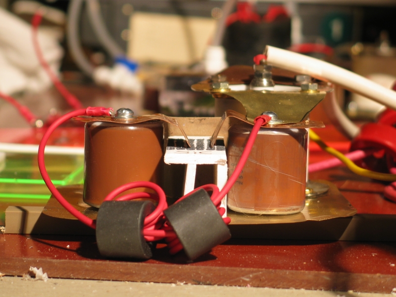
I went back and looked again; unfortunately, the stair protector is tall enough that I wouldn’t be able to get a floor under it without serious risk of surface discharge that would short out the caps. Fortunately, they also had a carpet edge protector, which looked pretty good except for the fact that it has only a tiny bulge at the edge, perhaps 2 mm in diameter. I gritted my teeth and bought a 3-foot piece (for five and a half dollars, not too bad), which I have now cut into two 17.75" chunks. If I start at the 2" mark and put one cap every 2.5", I get 6 caps on each side in a pleasant interlock. (The caps are 2.25" across, and will fit nicely.) Unfortunately, there is no way I can draw the profile of this extrusion in ASCII, so I’ll just have to photograph it.
First, however, let me revise the lousy diagram with a very rough approximation of the shape:
             o + Trig
             |
        +---   ---+---------+--------\       /---------+--------- GND
         | GP-70 |     ----------     o     o     ----------
         |       |    |    5x    |               |    5x    |
         | SPARK |    |   2 nf   |               |   2 nf   |
         |  GAP  |     ----------                 ----------
        +---------+---------+--------------------------+-------- - HV
(The spark gap is actually taller than the laser, as the 2 nf caps are actually fairly short; I’ve drawn it at the same height here for convenience.) Here are the photos:

Also unfortunately, I can only find 9 of the caps, so I will use 5 of them on one side and 4 on the other, making up the difference with 3 780-pf 30 kV caps, two of which will be on the baseplate in positions that were originally intended for 2-nf caps, and one attached to the far side of the spark gap. This will help establish a conduction channel in the gap very rapidly, so that it switches faster, and will total 2.4 nf, which is reasonable. (I may substitute something else for the cap at the back of the spark gap, depending on how I feel when I do the assembly.)
All the edges and corners need to be rounded before I can use these, of course, but I’m going to drill the holes first. (Ignore the holes visible in the photos above: they were already present when I bought the piece of extrusion.)
The channel will probably be about 30-35 mm wide, as you can see in the last picture. That would give me quite a bit of volume if the electrodes had wide faces, but as I mentioned, the edge of the extrusion is tiny compared with everything else I’ve been doing in this project; on the other hand, this is “back to baby steps” until I figure out what gives here.
I still have to figure out how to make a reasonable gas
enclosure and mirror mounts, and I have to decide on
preionization. I may also have to stabilize the baseplate,
as thin brass is quite flexible. (At this point, I have
marked it, but have not yet drilled the mounting holes
for the doorknob caps; my drillbit is dull, and the
hardware store is not open at this hour.)
(26-27 June, 2005)
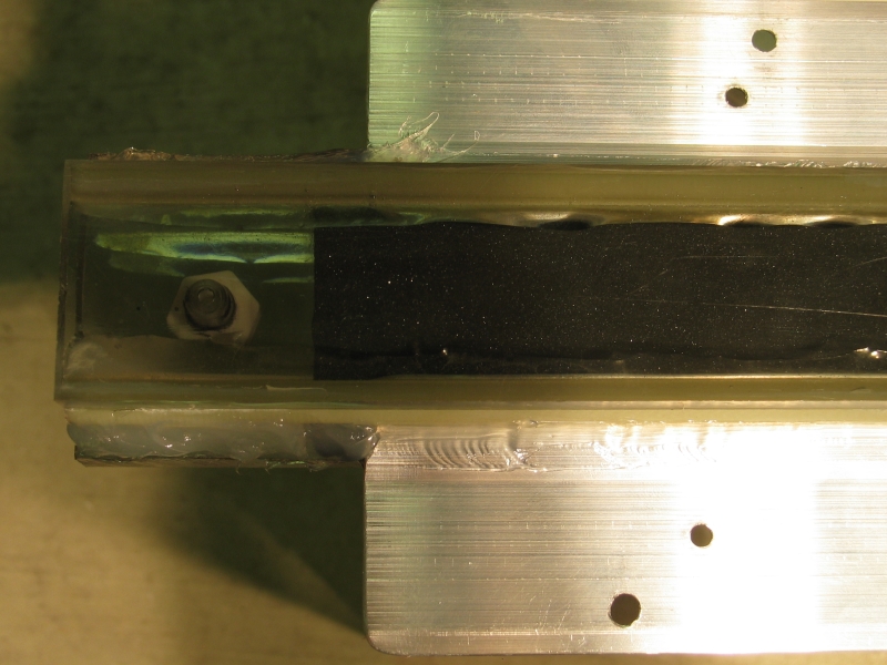
I have drilled the baseplate and the electrodes, and attached things temporarily to get a sense of how the layout could work. I’ve also rounded the corners of the electrodes.
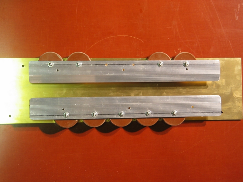
I had intended to use the white plastic bars (visible in the second photo) as edges for the plastic plate that will go under the channel, but they are too wide: they touch the baseplate. I may have to go to the plastic store and acquire something narrower, as the hardware store didn’t have anything else that seemed appropriate. Either way, I’m getting closer to a first test. Still need some brass or copper shim stock with which to attach the spark gap and its attendant doorknob.
(28 June, 2005)
On a hunch, I decided to try polishing the rounded corners of the electrodes by rubbing them with ultrafine steelwool. This wins: they are now bright, shiny, and smooth. With some luck, that will prevent them from sparking when I actually fire this thing.
I’m probably going to go to the plastic supply place tomorrow and get a piece of polycarbonate about 2.5" across for the lid of the channel. I think I can use one of the pieces I already have for the bottom, but I will need sidewalls, so I’ll acquire those, as well — they should have something suitable. I’ve got fittings for the gas inlet and outlet, and I’m thinking about mirror/window mounts for the ends...
(29 June, 2005)
That worked: I now have a piece of polycarbonate that I
can use as a roof for the channel, and I’m
acquiring various other bits, including some shim
stock. That stuff should be here within a day if it gets
ordered this afternoon. I can probably do initial
testing with faked ends on the channel: even a
microscope slide will pass a certain amount of UV.
(30 June, 2005)
As long as I’m waiting on materials (which are now ordered), perhaps it’s time to talk about how I expect this device to work.
This laser utilizes what is probably best termed a voltage doubling circuit, in which two capacitor banks are charged together, and then one is discharged through a fast switch that has relatively little resistance. The circuit formed by the capacitors, the switch, and the associated connections inescapably has some inductance, so it becomes what radio people used to call a “tank circuit” — a resonant circuit that will oscillate for a few cycles if nothing interferes. This doesn’t actually double the voltage, but there doesn’t seem to be a better term for it.
The resonant frequency depends largely on C (the capacitance) and L (the inductance), in a predictable way that I will pervert slightly: the 10% to 90% risetime is going to be on the order of 1.5 times the square root of L times C. In other words, if I fire off this side of the laser all by itself and measure the resulting oscillation, I should be able to tell what the inductance is, because I already know the capacitance (~10.4 nanofarad). (I may be able to do this test at low voltage, though not with the spark gap; if I manage to get it to work, I will report the results.)
What I expect is that the risetime will be about 35 nsec, because I think the inductance of the spark gap added to the inductance of the capacitors and associated physical structure should be on the order of 40 nanohenry. This corresponds to something like 175 nsec for a full cycle, which means that the resonant frequency should be a bit less than 6 MHz unless I’ve dropped a decimal place somewhere. Naturally, I hope that it will be faster; but I’m not betting on it.
In normal operation, however, things are somewhat different. Both capacitor banks get charged, and as the switched bank “rings down” during its first half-cycle, the voltage across the laser channel (which is between the two banks) increases rapidly; if the channel doesn’t conduct, it can get as large as ~1.9 times the initial charging voltage. Typically, of course, the channel does conduct, and that limits the voltage that can develop across it.
These things are difficult to measure, but in general, from what I’ve read, I think that the voltage rarely exceeds 1.2x the initial charging voltage. The advantage of this circuit is that when the channel begins to conduct, the capacitor bank that is driving it is looking into a negative voltage, which is even better than a dead short to ground, and the capacitors are discharging not so much through the switch as directly into the capacitors on the other side, so the risetime of the current (and power) in the channel is very short. (The fact that the capacitor bank is divided into two pieces gives you a little bit of help in this regard, because smaller C has inherently faster risetime.)
Nitrogen lasers using this type of circuit tend to have fairly good efficiency, relatively speaking, and are only moderately sensitive to the inductance of the switched side. This is part of why the Scientific American laser works. (Any talk of “the instant the switch closes” is simply nonsense: even if the word “instant” had any meaning in electronics or physics, which it doesn’t, there can’t be any such instant because the switch design has huge inductance and is free-running, so it is terribly slow.)
When the laser channel begins to conduct, electrons travel through it, bouncing off the gas molecules and (we hope) exciting some of them into the upper laser level. As I mentioned in the first page of this set, the electrons have to have a certain amount of energy in order to accomplish this, and that energy can be related directly to three parameters: the voltage across the channel, the width of the channel, and the nitrogen pressure.
My initial charging voltage will be 20 kV, but I doubt that we’ll see any more than about 10 kV across the channel once it is really conducting. The channel is 35 mm wide. If we suppose that we want about 100 V/T·cm, it looks like the optimum partial pressure of nitrogen will be just under 30 Torr. If it turns out that we need 200 V/T·cm, the optimum pressure will be just under 15 Torr, which is rather low. Fortunately, it is not necessary to be precisely at the optimum: in the papers I’ve read the peak appeared to be fairly broad, and anything within about a factor of 2 should be viable if we’re far enough above threshold. (This matches my experience with the commercial nitrogen lasers that I have operated.) Moreover, at least one paper reports that the addition of helium to the discharge causes a change in this value, and the experimenters reported their best operation at about 86 V/T·cm with helium constituting about half of the gas mix. (Rickwood & Serafetinides, “Semiconductor Preionized Nitrogen Laser”; see the list of references if you want more detail.)
(1 July, 2005)
Obtaining a smooth and even discharge is crucial to the operation of any nitrogen laser. There are various ways to accomplish this. One is to run at rather low pressure, where it is easier. That, however, limits the amount of energy you can get by limiting the number of gas molecules that are present. Another is to add helium to the gas, as mentioned above. This seems to have a stabilizing influence, and seems very promising. Alone, however, helium is not enough. A third is to preionize the gas in the channel, either by firing at a relatively high repetition rate to take advantage of lingering ions from the previous pulse, or by other means. Because nitrogen works better when it is cold, using a high repetition rate decreases both power and energy per pulse, not exactly what I’m looking for; because of that, and because I have no easy way to remove excess heat from the laser, I am not going to use this method of preionization. I do, however, want to preionize.
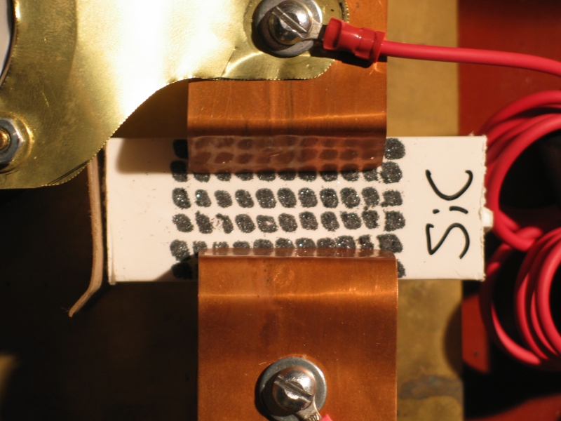
At least as a starting point, I’m going to use a fairly uncommon method that involves semiconductors. The underside of the top wall of the laser channel (a piece of polycarbonate plastic sheet), is coated with epoxy, and while the epoxy was still fresh and wet I sprinkled a mixture of carborundum (SiC) and graphite on it. At ordinary voltages, commercial carborundum does not conduct; but when the electric field becomes high enough, it switches to a highly conductive mode. (In fact, it has been used as a lightning arrestor for power or telephone lines.)
The discharge across and through the carborundum will generate lots of ions and a certain amount of UV light, which should, if I’m lucky, preionize the channel nicely. My main worry is that the mixture could conduct too well; but if the “on” resistance is even a few dozen ohms, conduction should switch to the laser channel at some point during the pulse. (The laser channel doesn’t have a well-defined resistance; but once it is conducting well, its effective resistance should be quite low. This, in fact, is part of what makes it so difficult to maintain the electron energy: you have to push huge current through the discharge in order to sustain appreciable voltage across it.)
Speaking of which, the next question is how long the electron energy will stay in the viable range, because this has a strong influence on the length of the laser pulse and the amount of energy in it. I will only be able to determine this one by measurement. If the laser pulse is well under 10 nsec long, then I’m not sustaining the E/p value well. If, on the other hand, the laser pulse is more than about 12 nsec long, then I’m doing extremely well.
Even given a pulse as short as 8 nsec, there is the optical cavity to consider. Nitrogen lasers are typically operated in what is best described as superfluorescent mode, with at most one mirror. A few people think this means that nitrogen lasers aren’t really lasers; those people have failed to do their homework. LASER stands for Light Amplification by Stimulated Emission of Radiation, not “Light Amplification Inside a Fabry-Perot Resonator”. Moreover, I have recently heard that some idiot is claiming that the nitrogen laser isn’t coherent at all (not true — coherence is not binary, it’s a measure, and essentially any light source has some degree of coherence), and that because it isn’t coherent, it isn’t a laser. This is absolute crap. Stimulated Emission is a coherent process, at the quantum level. This means that lasers, in general, have greater coherence length than most nonlaser sources; but an untuned dye laser may exhibit shorter coherence length than a nitrogen laser, a diode laser almost certainly exhibits much shorter coherence length than a HeNe, ...and the entire argument is garbage.
This laser, as it is currently configured, has an active length of about 17" and an overall length of about 23". (I say “about” because I do not yet know the actual separation between the mirrors or windows.) I will be using a ~95% reflective surface at one end and a silica window at the other, at first. I hope, later on, to have a somewhat more reflective output coupler. This is because light travels 60 cm in 2 nsec, which means that the leading edge of an 8 nsec pulse can make two full round-trips inside the cavity. That may not seem like much, but it’s probably enough to help narrow the beam to some extent, and if I haven’t saturated the gain, it will increase the power significantly. Having a more reflective output coupler becomes increasingly useful as the pulselength increases, again with the caveat that if I actually succeed in saturating the gain, the output energy won’t improve even if the beam quality does.
Actually, because I don’t have a suitable silica window yet, I may initially operate the laser with a microscope slide as its output window. That’s a lousy option, but at least I’ll know whether the laser is operating. Alternatively, I could use the fused silica lens that I currently have on the converted CO2 laser head. That’s annoying, but at least it passes UV quite well.
Then there’s the issue of gas mixing. How do I add
nitrogen to helium? (Helium is extremely light, and
will tend to float above the nitrogen without mixing
into it.) How do I know how much nitrogen I’m adding?
I have not fully resolved these issues yet, though I
do have some ideas about mixing.
(1 July, 2005)
I have been investigating mass flow meters on eBay. Lots of them show up, all apparently fairly old but mostly NIB (“New In Box”), and at what appear to be reasonable prices. My one worry is that they generally have low-voltage digital outputs, which seem entirely unsuitable for the nitrogen laser environment — the EMP (Electro-Magnetic Pulse) coming out of this laser will be huge, and that’s not healthy for logic chips.
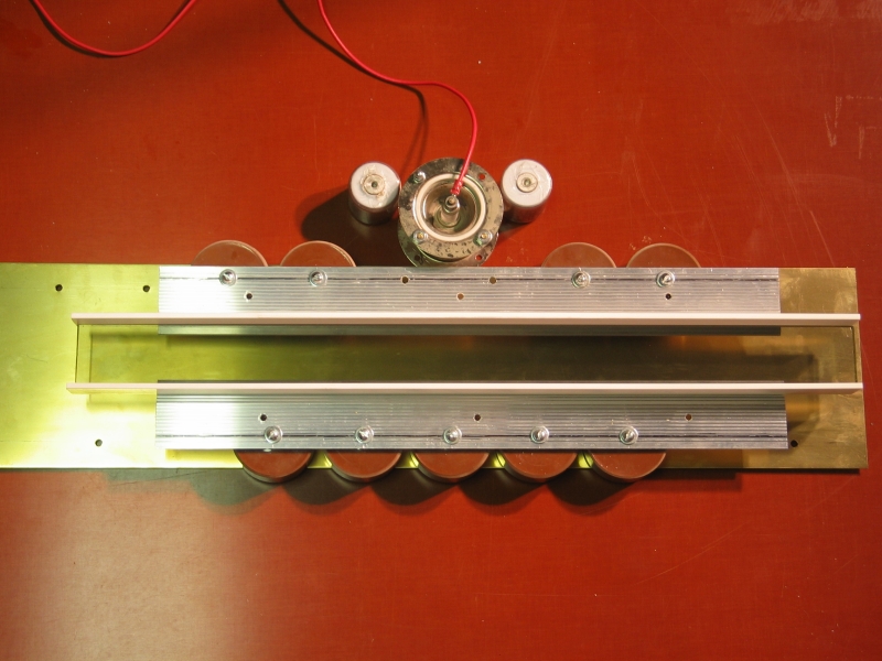
Meanwhile, I have put the adapters on the top plate, and glued it down to the channel with epoxy. That will take some hours to set, but should stabilize the structure considerably. Then I can put the bottom on the channel, after which I’ll fabricate the brass foils to connect the switch. At that point I will be very close to initial testing.
(Later that evening, after a run to the hardware store for various adapters...)
I now have a gas mixer, which may or may not work; I suspect that it is intended for turbulent flow, and I doubt that I’ll be running the gas through it fast enough for that. Milan Karakas suggests that heating and turbulence inside the laser head, from the discharge, will mix the gases adequately within a few pulses, so it may not matter.
(2 July, 2005)
Last night I tacked the siderails onto the channel floor and epoxied one of them down. (I had to tilt the thing to keep the epoxy in place, so the second one had to wait until this morning, but it is now done as well.) I’ve positioned the rails to make a "U" shape, which I’ll try to photograph as time permits. The rails, which are 0.250" diameter rod made of FR5/G11 fiberglass (a grade I didn’t know about until I found it in the MSC catalog), are spaced to put them just outside the actual channel; perhaps a bit tight, but it should work well if I’m careful about how I attach it.
I’ve also been thinking about structures for the ends; I need to be able to make minor adjustments to the mirror and window, and although it’s preferable to have the adjustment points be orthogonal, I may grit my teeth and just do some sort of triangular arrangement for simplicity of construction. One thing I’m fairly certain of: I will build the end structures and assemble them to be sure they work, before I actually attach them. It also seems likely that I’ll attach them with the channel off the base, as that makes it a whole lot easier to hold things in place while the epoxy sets.
The other advantages to taking the channel off the base
are the fact that I’ll be able to photograph it,
and the fact that I’ll be able to work on the foils
for the switch while the epoxy is setting. After that, I
should be able to start testing the thing, to find out
whether it has any chance of working. (Fingers crossed;
I have never tried this preionization method before, and
there is no absolute guarantee that it will work.)
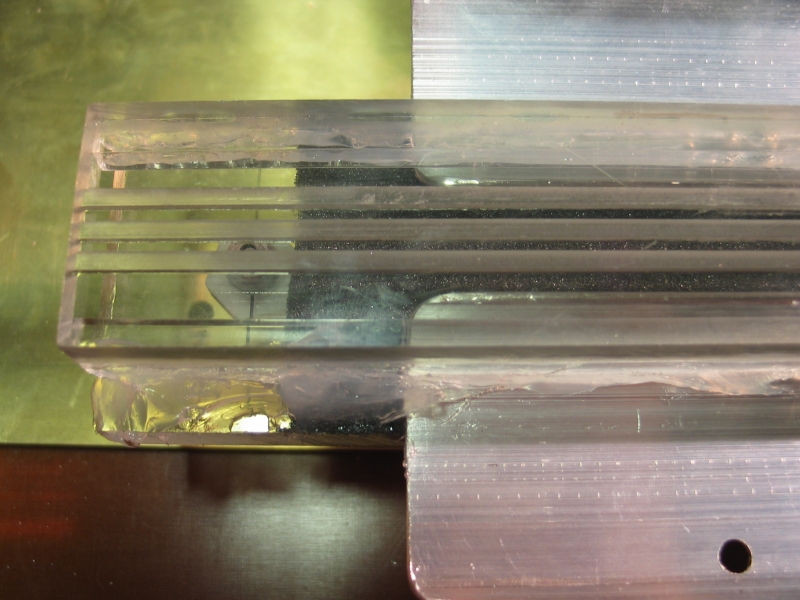
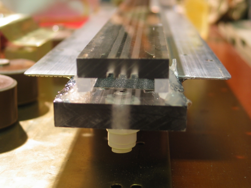
(Taken on the evening of 2 July, 2005)
The first photo shows the regrettable results of DTE (differential thermal expansion). I used FR5/G11 rod as the siderails on a polycarbonate baseplate, which then got hot in my car in the sun and warped as you see (fortunately only temporarily). If I do this again I will probably use polycarbonate for the rails. (This doesn’t resolve the issue of DTE between the polycarbonate and the aluminum; we’ll cross that bridge when we get to it.)
The second photo shows the channel, from below, with the preionizing roof glued to it, and the floor again. The third photo is a detail of one end of the channel; you can see the coating of SiC and graphite on the epoxy of the underside of the roof. You can also see a gas port.
The fourth photo (at left, second row) shows a view down the channel. The rails are quite reasonably straight.
The fifth one shows the completed channel (well, it doesn’t have any endplates yet, but the roof and floor are on it), and the final photo is a detail of one end.
I am either going to create endplates and install them, or decide to fake it for tonight so I can do some preliminary testing. Either way, I will almost certainly make the foils to attach the spark gap switch.
(4 July, 2005, early AM)
I built the foils, connected the spark gap switch, and faked ends by sticking a mirror on one end and some fluorescent acrylic plastic sheet on the other with double-sided sticky foam tape. It isn’t airtight, but if I run a continuous flow of helium, even a small flow, it will do.
I have succeeded in getting some sort of discharge in the channel, but I’m not seeing any laser light. Once I got the channel full of helium there was horrendous arcing at the ends until I put insulators under them, and after that I had some arcs occur under the channel. I can’t tell what’s causing them, or even precisely where they are; the easiest solution is regrettably obvious, if somewhat annoying: I have stuck a Variac [I think that’s a trademark] on the power supply and dialed back the voltage to perhaps 12 or 14 kV.
With only helium in the channel I get some pink sparks at the ends; but if I add some nitrogen it appears to even out somewhat and change color to grayish white. Unfortunately, I’m not seeing any lasing yet, and I’m now tired enough that I don’t think I’m fully safe. I have shut down for the evening, and will mess with this more upon the morrow if there’s time. One thing I will probably try is dialing up the voltage as high as I can without having any trouble from it. If necessary, I can sit the baseplate under about a quarter of an inch of baby oil; that would probably prevent any further arcs, at least outside the channel. For obvious reasons, however, I’d prefer to avoid doing that. On the other hand, there are worse things than a tub of baby oil. (A nice coating of something that’s resistant to high voltage would also work, and is probably fairly easy to arrange.)
(later that morning)
Milan Karakas points out that a full atmosphere of helium is considerably more than usual, and suggests that I pull vacuum on the channel. Even though this suggestion is tempting, I have several objections to it. First, I specifically intended this device not to require vacuum. Second, the ends that are currently on it are not airtight, and I’d have to rework them. Third, I haven’t gone to any great lengths to avoid leaks. Fourth and most importantly, the top plate is more than 2" wide, and the bottom plate is more than 1.5" wide. Both are 22 inches long. If I pull even half an atmosphere, that’s 3.5 * 22 * 7 lbs, and it’s trying to bend the aluminum electrodes because of the width difference between the two plates. I can’t see that as a prescription for joy in Mudville. On the other hand, I may not have much choice; see below.
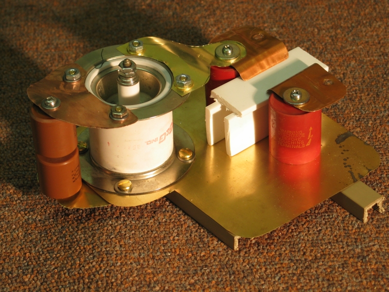
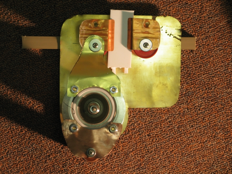
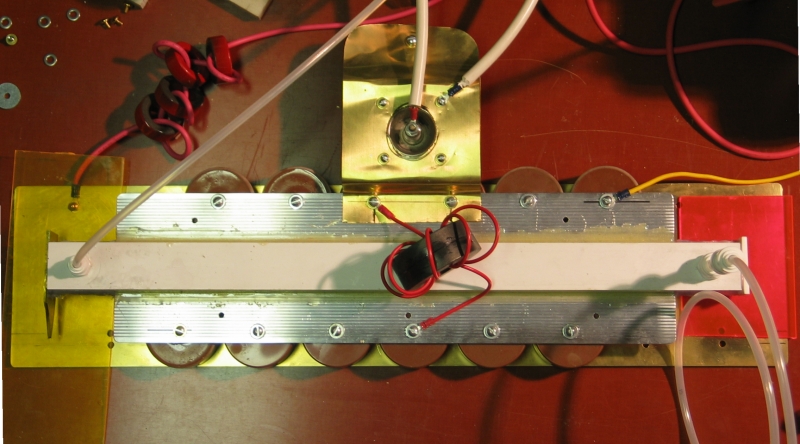
Here is an overview of the laser, from above:
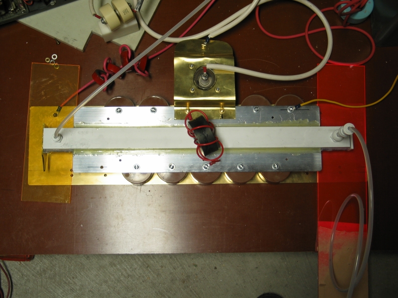
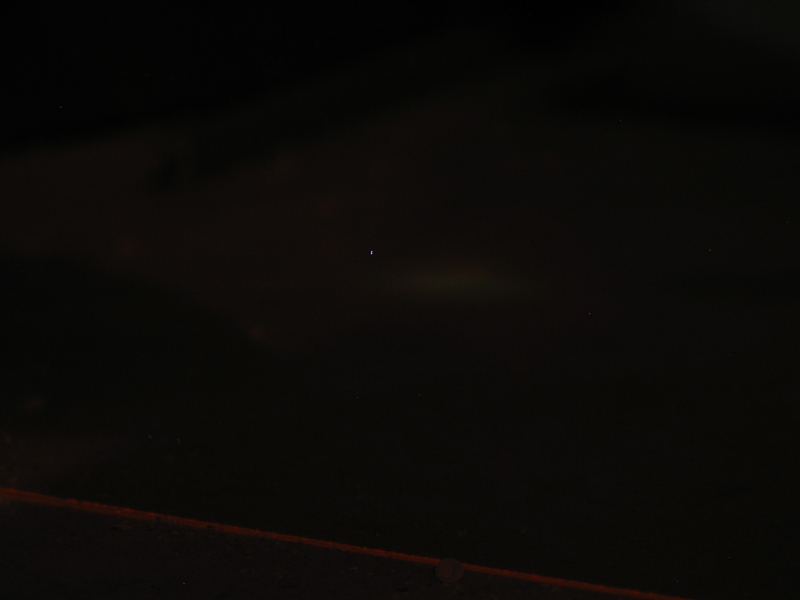
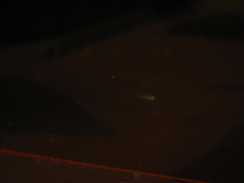
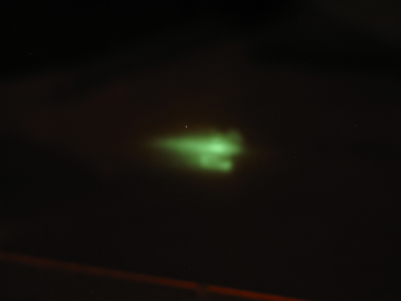
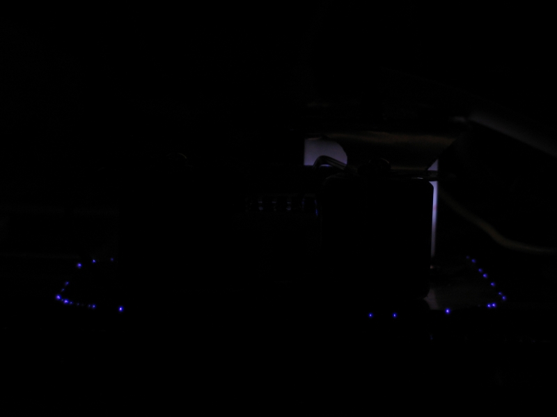
Here are some photos, showing what’s going on in the channel:
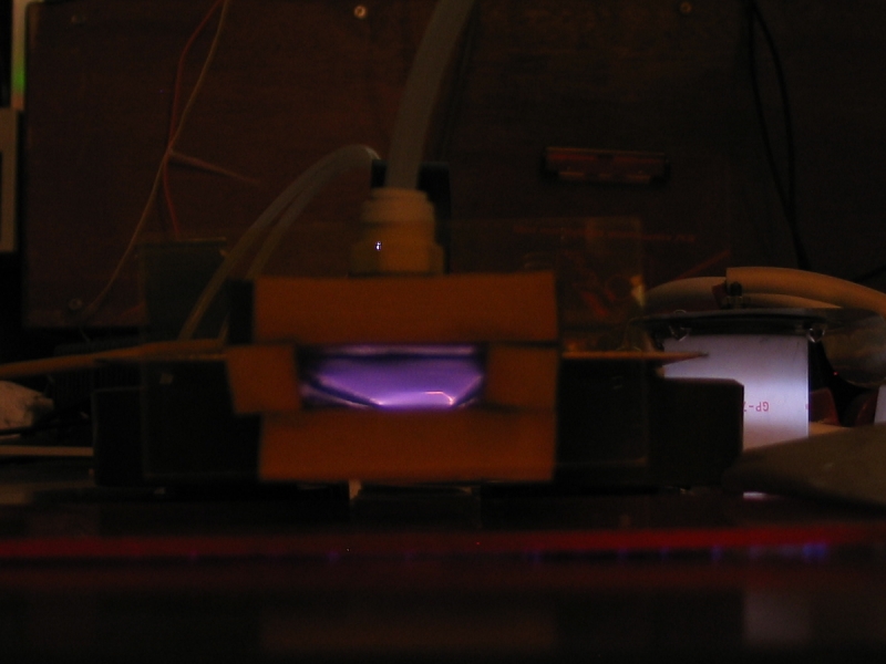
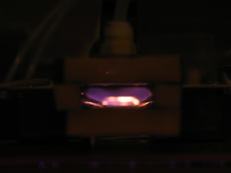
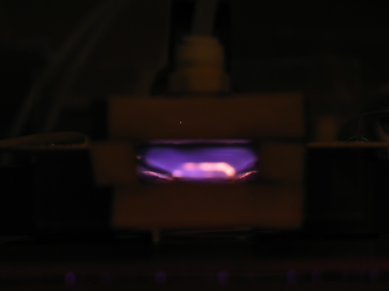
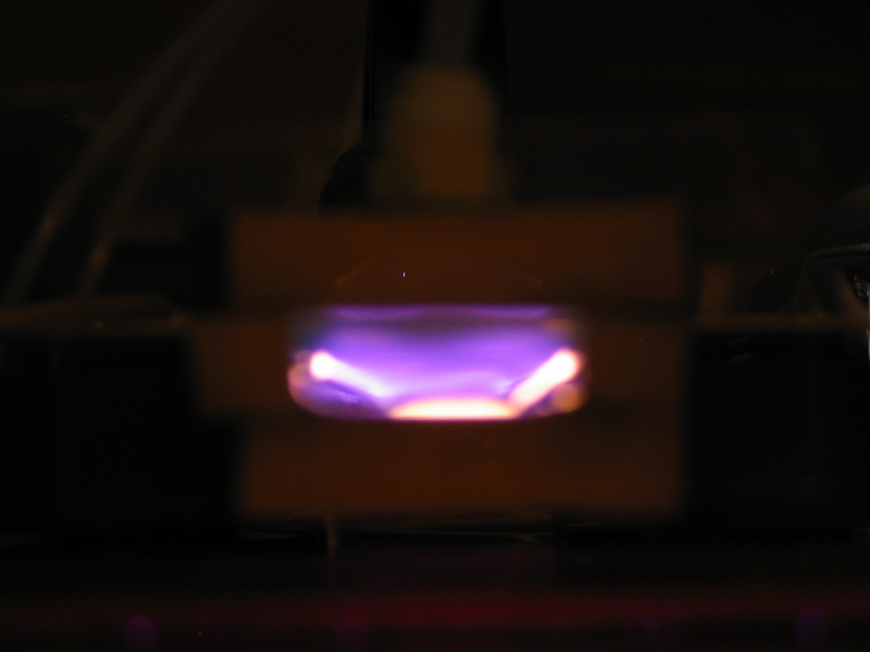
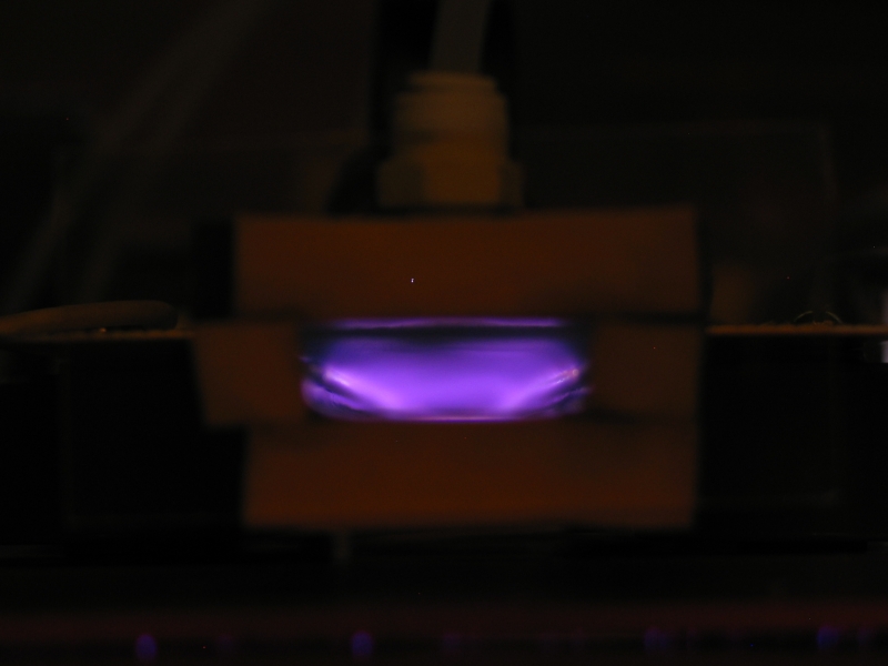
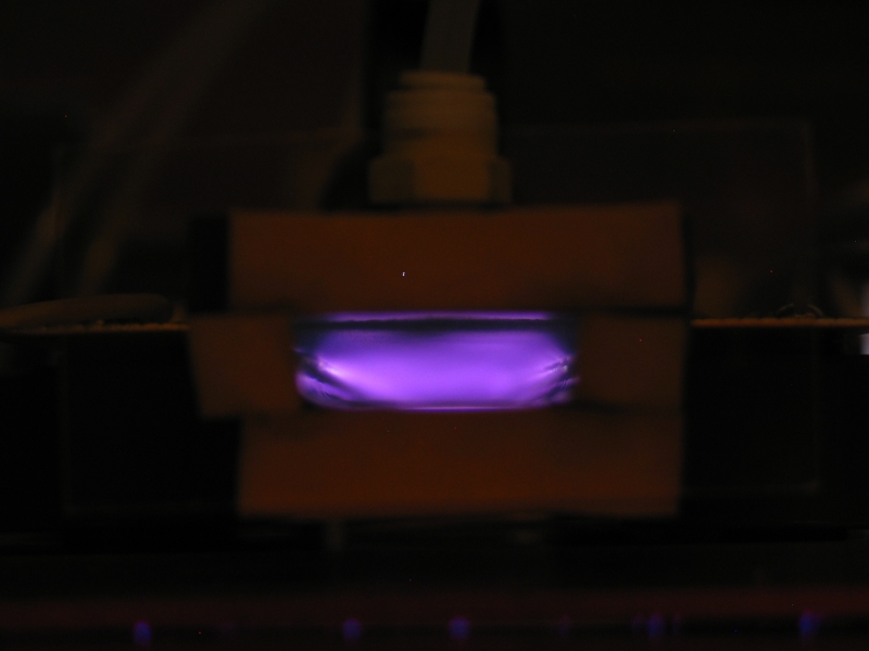
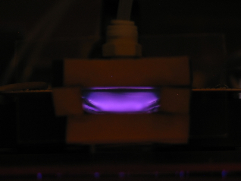
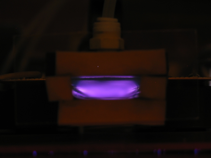
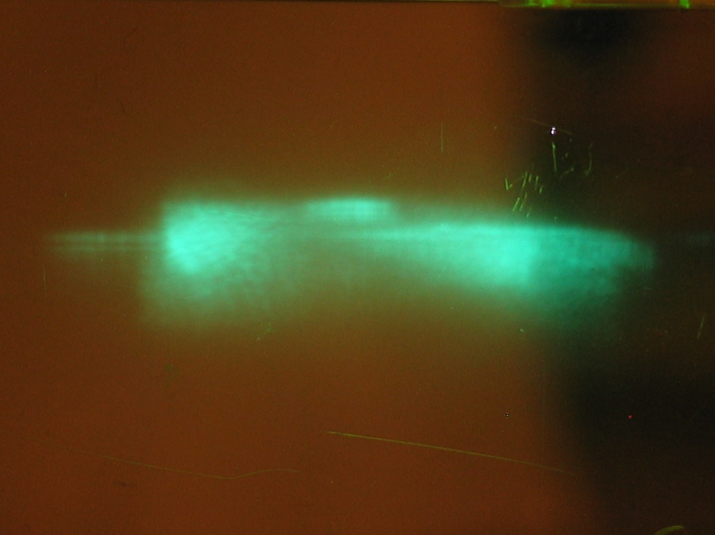
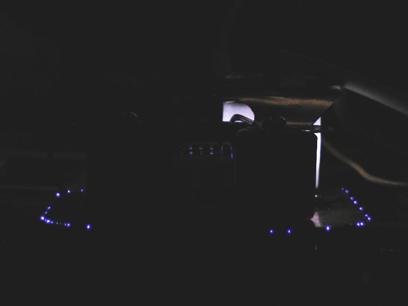
The first photo shows the GP-70 in addition to a view into the end of the laser. There is some sparking across the preionizer.
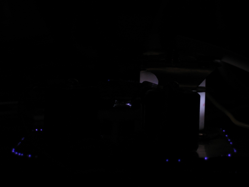
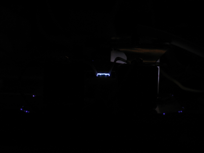
In the next photo you can see some discharge across the preionizer plate, and a spark toward the back. Note that even though you are looking through a piece of yellow-orange plastic, the discharge appears very blue or purple. (Because this is a crop, the largest size is “.12c.”, rather than the usual “.22c.”.)
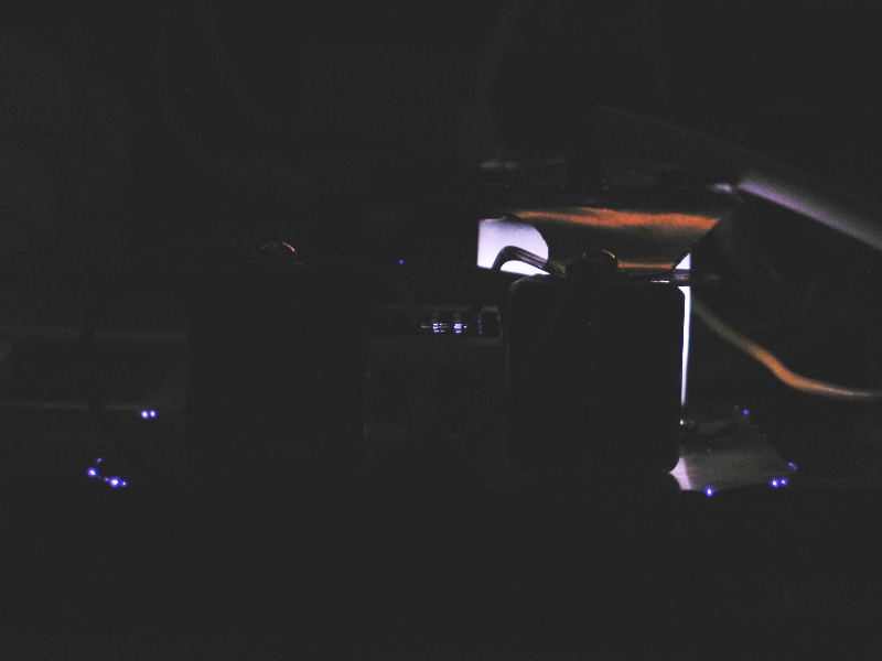
The next three photos show sparks. The one on the right is focused incorrectly; the sparks in the other two are out of focus because I was trying to capture the glow on the preionizer, which is quite strong. Unfortunately, I didn’t get the camera looking straight along the electrodes, but I think the workings are sufficiently well shown.
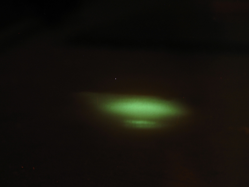
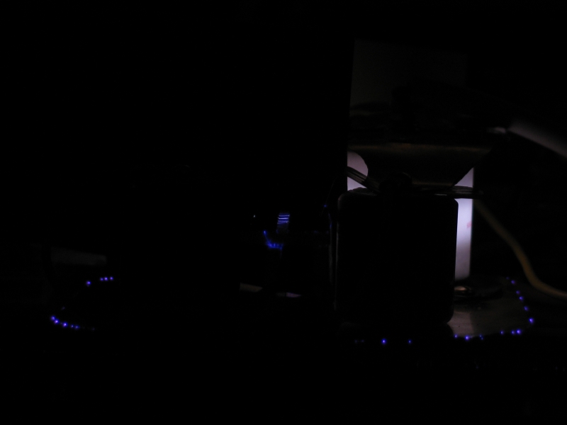
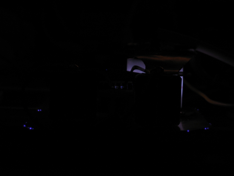
The last four photos show the device in more-or-less-normal operation, and should serve to illustrate some of the reasons why I’m not seeing any lasing here. The discharge I want is a nice even bright ribbon between the electrodes. What I’m seeing instead is a diffuse glow, some of which is on the preionizer, some of which is in the middle of the channel, and some of which is forming a sliding discharge along the floor of the channel. This is perhaps shown most clearly in the last photo, particularly at the right front edge of the discharge, where you can clearly see glow going up and down from the edge of the electrode. I would much prefer to see the glow going straight across to the other electrode... sigh... (Hey, at least it’s glow. Not bad, at 1 atmosphere total pressure.)
I need to rethink this very carefully, because it isn’t too far off, but it certainly isn’t a laser yet, and I need to learn the right things from it.
(That night...)
The more I think about this, the happier I get. True, it didn’t lase, which pisses me off; but if I’m judging the pictures correctly, it certainly does demonstrate that SiC/graphite epoxied onto the face of a plastic bar is a viable preionizer. That’s outstanding.
The next step, inasmuch as I think too much of the energy is going into the preionizer material, is to ditch the graphite and try Carborundum alone. If that works well, I’ve got a truly nifty idea for a charge-transfer laser, which I’d seriously think about as a rebuild of the CO2 laser head, because at that point I’d have good reason to think it was worth doing. (Also because it’s dirt easy, and it keeps the capacitors out of the laser gas.)
(Tuesday, the 5th)
I went to the hardware store. Got another piece of
carpet edging, two pieces of aluminum “L”
that I can use to widen the “U” channel on
the CO2 laser, and a nice piece of plastic imitation 1x2
from which I can cut sidewalls for the CO2 laser when I
go to rebuild it. On edge, this item is just about
precisely as tall as the 900-pf doorknobs without their
contacts. Inasmuch as I can put the aluminum L at a
slightly greater height than just coplanar with the
bottom of the U if I want, I should be able to get
everything to fit together nicely. ...But that’s
later. The plan for now is to redo the small laser, with
channel width of perhaps 20 mm (instead of 35), and with
only carbo — no graphite. We’ll see how that
works. ...If it works.
(July 6, 2005)
Last night I managed to saw a 22" length of the thick polycarbonate that I’m using as a roof for the channel. It only took me a little over an hour, and I only broke about 6 jeweler’s-saw blades. Grump. (I had the cut going quite well on one side, but I kept trying to even it out from the other. This was ill-advised.) I like the jeweler’s saw because it cuts a very narrow kerf with a nice edge.
In any case I did finally finish that cut, using my last blade, and went on to chop the aluminum extrusion in half. The blade remains intact; we’ll see whether I can get any further use out of it. (I would like it to be said of me that at the height of my powers I was occasionally able to dull a jeweler’s-saw blade instead of breaking it; but I think I’ve only done that once or twice.)
I have an idea about how to get a thin and even coating
of SiC onto the underside of the channel roof: I am
thinking about diluting the epoxy a bit with isopropanol,
so that I can wipe or brush on a thin, even coat. (The
first roof has some areas where the epoxy moved after I
put the SiC/graphite mix on it, leaving irregularly
shaped thin regions. Not what I had in mind, and not a
prescription for good operation.) I suppose I could use
varnish rather than epoxy, but for now I think I’ll stay
with a minor modification of something that I know to be
viable. At least epoxy is intended for attaching things
to each other...
(7 July, 2005)
I have drilled and tapped the gas port holes in the new top deck, and applied carbo to it. I did, indeed, dilute the epoxy with a small amount of isopropanol (regrettably only 91% pure — for some reason, nobody around here carries the 99% stuff) before applying it. I have also drilled the holes in the electrodes, but I haven’t done any shaping on them yet.
While we wait for the epoxy to cure, let’s take a look at what we can reasonably expect from this machine. I’m going to pull some numbers out of the air, and see what they appear to imply.
So: Timing.
There is a considerable (and somewhat variable) delay between the initiation of the trigger pulse and the time when the spark gap actually begins to conduct significantly, so I’m going to ignore the trigger and concentrate on things actually happening at and in the laser. Time 0 is when the spark gap begins to initiate. By about 1 nsec, the conduction channel begins to grow. By about 5 nsec, the spark gap should be conducting reasonably well, and the voltage on the primary side capacitors should be starting to drop. Somewhere around 30 nsec, the voltage across the laser channel should be at 12 kV, and the channel should begin to break down fairly rapidly. My guess (and it is purely a guess) is that within a few nsec the channel will be conducting reasonably well, and we’ll be pumping the upper laser level. My further guess (as I mentioned in the previous section) is that this will continue for about 10 nsec, after which the voltage across the laser will have dropped below 8 kV, and we will have ceased to pump the upper level effectively.
At 12 kV, 10 nf holds about 720 mj. At 8 kV, it holds about 320 mj. This means that during our precious 10 nsec, we are depositing about 400 mj into the gas, for an average power in the discharge of 40 MW. That’s not very high, but perhaps it will do. Notice that 40 MW at 10 kV is only about 4,000 amperes; that corresponds to an effective resistance of 2 ohms. (I have no clue whether that’s a reasonable number, but there may be some discussion in one or another article, if I can find it.)
The gas volume is about 0.25 cm x 2 cm x 60 cm or so, for a total volume of 30 cc. 400 mj into 30 cc is roughly 13 J/l, not really very much energy density... (Though I should actually go compare it against published results from other lasers before I say that.) Again OTOH, some of that energy goes into the preionizer, and as of right now I have no clue how much that will be, nor do I have any brilliant notions about measuring it.
Ignoring the preionizer for the moment (or, rather, just subsuming it into the total), if I can get efficiency as high as 0.5% from the actual energy deposited into the discharge during the active period, I should see about 2 mj out. If the pulse lasts 8 nsec, this corresponds to average power of 250 kW, which is modest but certainly nothing to complain about. If the efficiency gets any higher, I will be a very happy camper.
Now: Pressure —
For E/p of 80 V/T·cm, with 8,000 V on a 2-cm-wide channel, we can pump about ... (I’m going to get extremely explicit with the arithmetic here.)
80 = 8000/2T, where “T” is the pressure.
First off, divide both sides by 80:
1 = 100/2T
Now multiply both sides by T:
T = 100/2, so...
T = 50
50 Torr isn’t bad at all.
If it turns out that E/p really does need to be 200, however, I’ll get peak output around 20 Torr, which is a bit low. Inasmuch as I have no way to determine the partial pressure of N2 in the system, I probably won’t know (at least at first) where I am with this one, but it doesn’t much matter to me at this point. I’m more concerned with whether the machine will lase at all.
I pulled values for some extremely key parameters out of thin air, so this is all horsepucky until I can make actual measurements on an actual real running laser.
So, why bother?
Well, it’s like this: If you have a recipe, and you follow it blindly and exactly, it may work. But if it’s a cake recipe that was developed at sea level, and you live in Colorado Springs, it most certainly will not work, and unless you get into understanding the difference that makes the difference, you won’t have a clue about what to change in order to get it to work.
What we are dealing with here is a mildly complicated little thing, in which there are several interacting systems. (If you haven’t read Zen and the Art of Motorcycle Maintenance, it may be of interest.) It is necessary for lots of parameters to work together to bring you to the “sweet spot”; some of the parameters can be off optimum without preventing the device from working, but you begin to lose efficiency. In comparison with, say, the fusion resonance of Boron 11 and a proton, the sweet spot here is quite large, and the nitrogen laser is a very tolerant beast. It will work over a broad range of nitrogen partial pressure, voltage, channel length & width, and so on. Getting real performance, however, is not so simple. I once visited Avco-Everett Labs, and one of the designers there told me that anyone can get 250 kW out of a nitrogen laser. It’s not so easy, he said, to get half a megawatt, and only people who really understand what they’re doing can get a full megawatt. Having built several half-assed nitrogen lasers, I think I agree with him.
To return to the recipe metaphor, if you are developing part [or all] of your recipe yourself, as I am here, you seriously need to have some kind of feel for the parameters involved and the principles of operation, because otherwise you haven’t got a prayer of getting it right on purpose, and the chance of accomplishing it by accident is exceedingly small. This, btw, is why I’m so steamed about Jim Small’s explanation in Scientific American — it prevents people from achieving a real understanding by filling their heads with something else. If you already “know” something, it’s really hard to find out! (Once you read that the nitrogen laser puts out a pulse about 6 or 8 nsec long because it bottlenecks in the lower laser level, there is less chance that you will think to ask what governs that, and whether 6 nsec is actually a reasonable value. I had to read a lot of papers before it began to dawn on me that pulsewidth of 6-8 nsec at a few dozen Torr is not really likely to be a bottlenecking issue. In fact, I had to have it hammered into my head by someone speaking to the issue very explicitly.)
By playing around with the numbers, I can continue to develop some sense of what may be going on inside the laser; but I have gotten to the point where I can invent these numbers only by doing a fair amount of studying in this area (pulsed HV, nitrogen and excimer lasers; in the broader sense, electronics and physics), and by building some devices (nitrogen lasers, flashlamp drivers for organic dye lasers) and thinking carefully about how they worked and what appeared to be going on inside them.
All the same, even though I have some experience, it is important to remember that handwaving is handwaving, and that guessing about this is not the same as measuring it. You can very easily lead yourself down the garden path, thinking that your device will perform at a particular level when in fact some of the parameters are ’way off optimum. We all, I think, exhibit a bit of wishful thinking from time to time. (Hey, I am expecting this current rebuild to lase, and even that could be crap!)
At any rate, I will return to construction shortly. I have just received two fused silica windows, 12.5 x 25 mm, at least one of which will go onto this version of the device and will allow me to get some output. Speaking of which, I was thinking, last night, about building a small sputtering chamber so I can coat things with Cr, which has reasonably low loss at low thickness; that would allow me to make output couplers. (I have a few Cr-coated beamsplitters, but they are plain glass rather than FS, and they are thick enough that I would probably lose much of the output. Sigh.) This reminds me that I may have some beam directing mirrors intended for excimer laser use at 308 nm, which could work quite nicely as partial reflectors for 337 if they are made of FS rather than glass. I’ll have to check and see.
More as it transpires...
Later that afternoon:
I have drilled a new line of holes in the baseplate to
put the doorknobs 1 cm closer together, and I’m now
gluing the roof on the channel. It looks like the
electrodes are about 19 mm apart, which is close enough
for folk music. It is also clear that the piece of
polycarbonate that I want to use for the floor of the
channel will fit between the rows of doorknobs, which is
a relief. Once the epoxy has set, I will see about
positioning the floor. I may even substitute a different
floor, in order to maximize the probability that the
discharge will go straight across from one electrode to
the other, rather than ducking down to the floor and
running across it. (Surface discharge is easy, and the
path across the floor probably has lower inductance
than the path above it, through the middle of the gas.)
(8 July, 2005)
Milan Karakas has been doing a few tests with chunks of silicon carbide, and has been looking at two patents for preionization of lasers. The results are somewhat confusing, and I’m not entirely sure how to interpret them, partly because all of that uses massive blocks of material, whereas I have a thin coating of scattered grains. In any case, what Milan sees is a few small white sparks, close to where his electrodes touch the surface of the SiC. He does not see anything remotely resembling a uniform glow, and he does not see any light at a distance from the contact region. This is not a happy thing, but again, I am not sure how well it compares with my setup.
Worst case, I figure I can always go to graphite and see how that does. I may even build a little tester, just a couple of doorknobs, a switch, and a sheet of material to be checked, with a lid over it so I can fill the space with whatever gas I want to try it with.
In the meanwhile, after I glued the electrodes onto the new channel roof, I discovered that one of them was not correctly placed. Had to break it loose, fuss with it, and reglue. This morning I added more epoxy for strength, and I’m now waiting for that to set before I attempt to put a floor on the thing.
Speaking of floor, I have sawn off a 22" length of 3/8" polycarbonate to serve as a floor, and I just milled three slots in it; this should help prevent the discharge from tracking across it, by making the length of that path much greater.
(That evening...)
Here are two photos, with the channel upside down because I have just glued the floor on:
Notice that this time the floor is a “U” with rectangular bars as sides instead of round rods; the bars are acrylic, and I’ve attached them to the floor with cyanoacrylate adhesive. I know, DTE issue again, but I used materials I had on hand, and this is a test laser, not a showpiece.
With some luck, the RTV that holds the floor to the
electrodes will be essentially cured by some time
tomorrow, and I can attach temporary ends. Once the
seal on those is reasonably firm, I can run this
device. Milan Karakas suggested that a microscope
slide wouldn’t chew up too much of the output, and
that it also wouldn’t distort the color of the
discharge as much as the piece of fluorescent acrylic
I used on the previous channel. I have a few slides
that have much less green color than most, and I just
checked one with a mid-wave UV lamp; he appears to be
correct about the UV absorption, which is only moderate,
and he is clearly correct about the color distortion,
so I will probably use this slide as the output window
for initial testing.
(about 8 am, 9 July, 2005)
I woke up early, and couldn’t resist. Went down to the lab and tested the laser. It only works over a narrow range of gas settings, and only at relatively high voltages, so my guess is that I’m not getting the kind of preionization I want. The next channel will use graphite [Note, added in proof: no, it won’t; see testing results, below], and that will give me a good comparison among the materials I’m trying. If that doesn’t do what I want, Milan Karakas suggests stripes of silicon carbide, with narrow gaps between them in which sparking can occur. That actually seems like a pretty good idea. (There is also the fact that graphite dust is likely to come off anything I coat with it, and get all over everything inside the laser, including the mirror and the output window. Hmmm...)
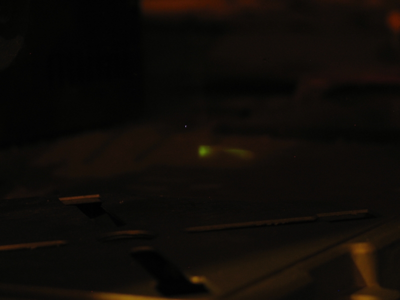
Meanwhile, here are some photos. First, incipient lasing. This is the kind of thing I was seeing with the CO2 laser on the previous page. (There is a small whitish spot, near the center of the field; that’s almost certainly damage to the sensor. Just below and to the right of it is a pale bar on the fluorescent acrylic sheet that I’m using as a target.)
Next image: it just begins. You can already tell that the mirror is not well aligned.
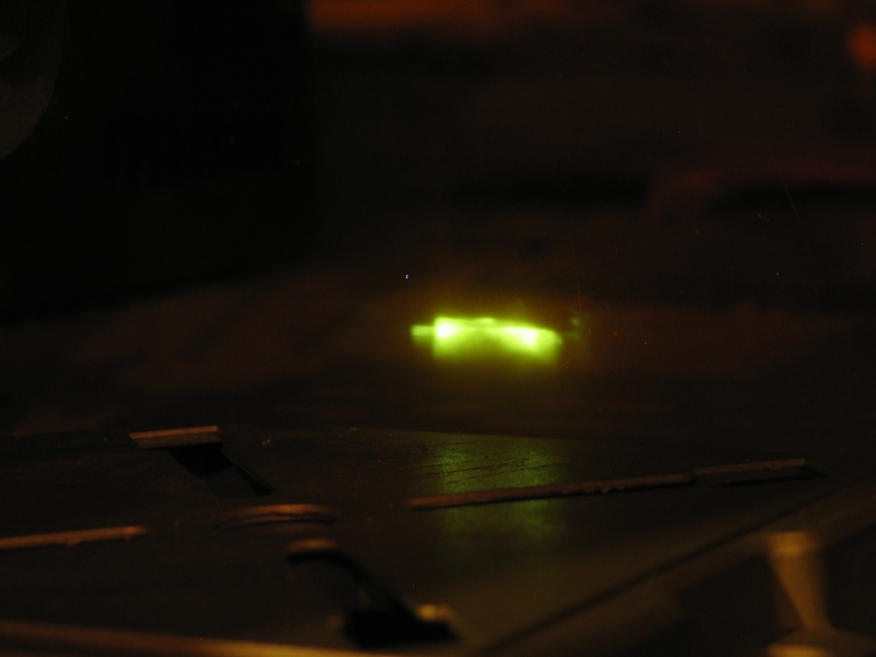
Finally, two images with the thing actually lasing, though not as well as I’d like: the beam is variable and irregular. On top of that, the one on the left is out of focus (my bad; sorry). Also, as I mentioned, the mirror is not aligned correctly.
I should probably note, at this point, that it is one hell of a lot easier to take a slightly nonfunctional surplus commercial laser and get it running or even rebuild something that came out of a dumpster than it is to build one of these from scratch. You learn different things each way, though, so it’s nice to have the opportunity to do both.
Cheers!
(11 July, 2005)
Milan Karakas notes that two patents that he has seen, which
cover the use of SiC for preionizing CO2 lasers, had gaps
between bars of the stuff rather than flat plates. This suggests
some sort of stripe or fishscale arrangement; but before I
go building several more channels I would really like to
know whether this idea will work, so I have built a little
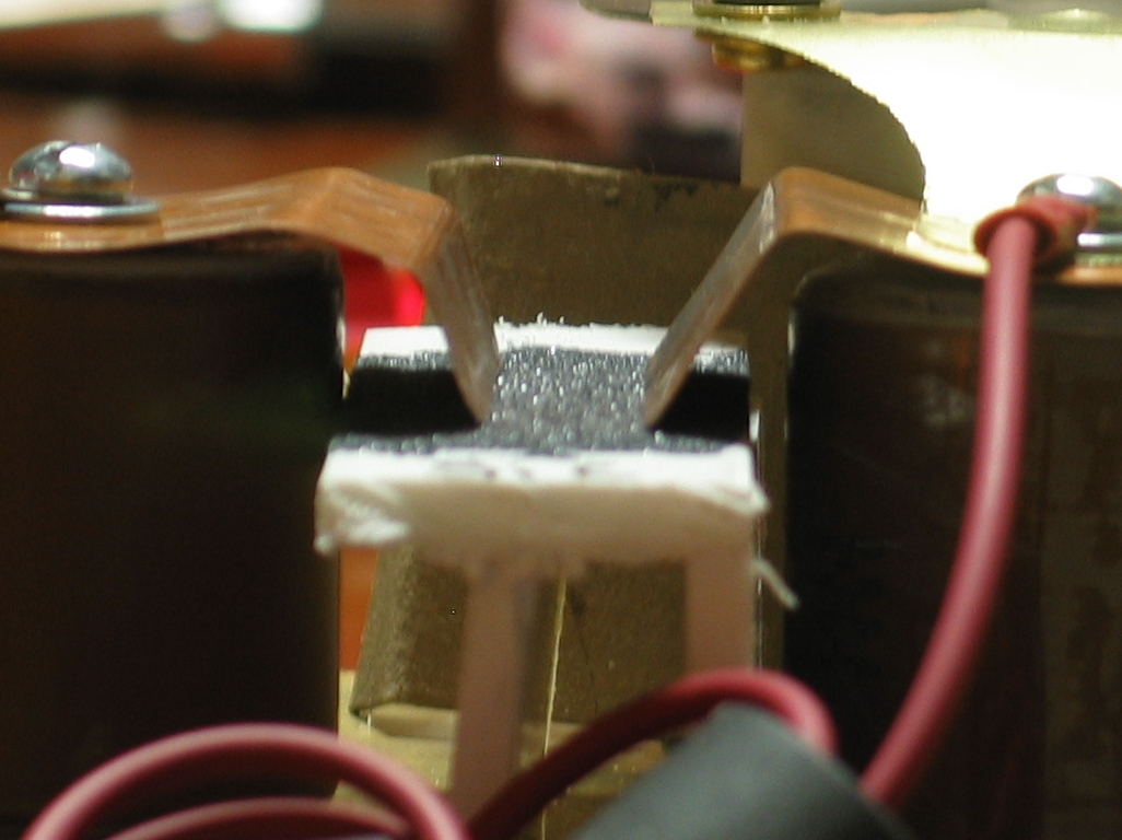
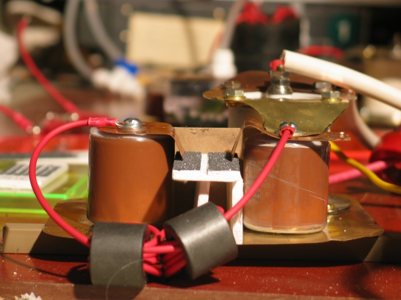
tester out of bits and pieces that I had lying around:
The two brown doorknobs at the left are 200 pf each; I’ve
put them in series to make 100 pf, just to get a little current
going in the switch. (A spark gap, at least one of this type,
needs about 10 amps to form a good conduction channel. If you
can cause that to happen quickly, you get better switching.) This
arrangement is partly a holdover from my original design, which
was going to use 2700-pf caps instead of the red 570s that are
in the actual device. As it stands, it slightly unbalances the
circuit, but I hope not too badly.
I have not yet built any test pieces, which is why the active
section (between the two copper contacts) appears white instead
of black. (It now being 2 am, I think that will have to wait
until tomorrow.) I also haven’t put a charging inductor
or resistor on, between the red doorknobs, but that’s
trivial.
My one worry is the possibility that I won’t be able to
put a full 20 kV across this, because there might be a surface
discharge from the baseplate up the white bars that support
the actual test piece. I suppose I can drop another thin sheet
of mylar or something under the test piece, or knock the bars
loose and put something of the sort underneath them; but it
may not be an issue — with any luck I’ll get results
even at lower voltages.
Took me 3 bloody hours to build this device, btw. I sure hope
it provides some useful info.
(During the day, 11 July, 2005)
I am now making 3 test pieces. One is SiC, one is graphite,
and one is something that I will call “Scidmorite 5”
for the moment. I have also gone to the local rubber stamp
place and inquired; if I bring them camera-ready artwork,
they can make a stamp for me in a few days, for $25. I think
I’m going to do this, as it appears to be a very
straightforward way to test the “islands” or
“fish-scales” idea.
(Late that night...)
I have replaced the 570-pf caps in the tester with 900-pf
caps that have lower-inductance terminations. I have to
change some other things now, which is annoying, but that’s
life. At least I can get it to spark over a short distance in
air, which means that both caps are charging and that the
switch works.
(Some time later)
We definitely have something going here. I can see some little
spark-showers across the surface of the Silicon Carbide. If I
turn up the voltage high enough, I usually get one bright white
arc, but at reasonable levels it’s just the streamery/sparky
stuff. Beastly difficult to photograph, unfortunately, as it
is not at all bright. In fact, even with the room rather dark
I can barely see it by eye.
I should note that the electrode separation, at voltages
essentially identical with those I’m using in the actual
laser, is perhaps 1 cm; this argues that 3 or 4 cm is
considerably more than would be viable. I have to decide
what to do about this.
Next test, per suggestion from Milan Karakas, is a corona
test in which I put aluminum foil underneath, say, a microscope
slide, and connect it to one of the electrodes. Should be
very easy to set up.
Well, I could hardly see what was going on with that,
though there did appear to be something happening.
I actually had to use thin brass shim, because I didn’t
have any aluminum foil down there that I could find, but
I’m sure that works. Still, as I say, I could barely see
anything.
Where I did see something, as I mentioned, was with
Carborundum. Here’s an overview of the corona around the
base as well as the experimental section. The pale moonlike
glow at the right rear is the spark gap...
Here’s a close-up of the experimental section, and
then 10 shots at about 20 kV. (Note that because these
are crops, the largest version of either image is the
one you get if you click one of the little ones.)
Even harder to see in the photos than it was by eye, but
that’s life. In any case, I am now becoming
increasingly clear on what I am likely to have to do in
order to get real preionization going in the laser. Next
we try the fish-scale thing, to see whether that confers
any advantage. If not, I’m going to go with a much
narrower band of SiC than I’ve been using so far.
I’m also going to get the stuff applied as thickly
as I can, as that seems to help a little.
Here’s a tweaked copy of that last photo, in which I’ve
increased brightness and contrast so you can see the
sparks better. While the majority of the fun is right
where the electrodes touch the SiC, there’s stuff going
on all the way across.
(The Next Day)
I have now made some dot tests, using part of an old rubber
stamp that I got yesterday for 2 bucks. The epoxy is setting,
and when it’s done I will see how they do. I did 1 with SiC,
fairly tightly spaced, and 2 with “Scidmorite 5”,
one loosely spaced and one tightly spaced.
...And again, it looks good for SiC. I am getting nice
little sets of sparks, even with gaps of >1 mm between
the lands. Now I have to figure out how to create a roof
for the channel that has a suitable pattern of this
stuff, and I have to be optimize it for the right
voltage. Unfortunately, because there’s a laser
channel a few mm away, which will start conducting at an
unspecified voltage and time, I have no clue what the
right voltage is, so this is going to be a good trick. I
think I can presume that I will never see more than
about 20 or 25 kV across the channel, which gives me an
upper bound, but the lower bound is not quite so simple.
OTOH, I think I am going to aim a bit high, because I
get sparks on the current test piece if I run the
voltage up all the way to as high as I was running the
laser, and also because the channel presumably conducts
at a lower voltage if it gets preionized extremely heavily.
Hmmm: I rearranged things so that there were three sets
of gaps between the electrodes instead of two, and now
I no longer get sparking even at my current max, which
turns out (measured indirectly, somewhat later) to be
about 16.7 kV. I also tried the other material, but
didn’t see much of any action. Seems like I have
my work cut out for me: how do I create a roof that has
three fairly narrow sets of gaps (or four very narrow
sets) between islands of SiC, and also has reasonably
good contact with the electrodes? I may end up gluing
narrow strips of brass shim to the edges, and letting
those make contact...
It occurs to me that if I can lay down a fairly even and
thin layer of epoxy, I can drop some sort of screen down
on it, and drop the SiC on top of that. After the epoxy
sets, the screen will be stuck to it, but the SiC won’t
be stuck to the screen. Unfortunately, this makes the
sparks jump over the lines of the screen, taking a longer
path. Barring that, there is a possibility that LisaJulie
Peoples and I discussed, a day or two ago: use a screen
that won’t stick to the epoxy, and can just be
peeled off after the stuff sets. Not sure whether I may
be able to soak wax into some sort of fabric screen (which
I have: a mesh bag that you throw delicate laundry items
into and then toss into the washing machine).
I will, btw, attempt to photograph the test piece in action,
later this evening.
(As promised...)
First row: the wider (3 gaps) setting, from above and then
from the side; then the narrower setting, 2 gaps. Second
row: first, about 10 firings of the wider setting, at about
16.7 kV; next, even at considerably lower voltages, the
narrower setting often sparks; last, perhaps 15 or 16 firings
at low enough voltage to avoid sparking, and links to
higher-contrast versions.
Even with reduced voltage, the 2-gap setting is a lot
more sparky than the 3-gap setting. I could guess that
a set of 4 gaps (at this width per gap) would be enough
to handle 40 kV or so... I am still somewhat worried
and confused about what I need to do for the laser, in
order to match the preionizer to the channel, but my
current thought is that 2 gaps of this width would be
likely to spark before the channel gets a chance to conduct,
so I’m going to go for three, more if I make them
narrower.
(Next day, 13 July, 2005, after sleeping on it...)
It occurred to me that there is one more test (or set
of tests) that I need to perform: one fairly wide gap
rather than a series of narrow ones. This is analogous
to the pin-gap method that you can see on
the previous page. I am now waiting for the epoxy
to set on a first test piece.
The other big question is whether I have to provide a
highly conductive path from the electrodes to the edge
of a narrow strip of semiconductor with one or more gaps,
or whether the semiconductor itself will work. I may
have to move my second doorknob back still further, and
test lengthwise on a strip of plastic rather than across.
First results: I thought about my first test piece, and
decided to abandon it. Instead, I ditched a 1/8"-wide
cut down the middle of a piece of the white plastic with
an end-mill, applied epoxy to the “high ground”
on either side, and loaded the surface of the epoxy with
SiC. I have just tested this, and it worked very nicely,
even at ~16.7 kV, even with the contacts about as far apart
as I could get them. My guess is that this is a viable
configuration, and unless I think up some good reason not
to do so, I will proceed to build a channel roof with a
1/8" groove down the middle of it. Again, I will try to
photograph the test piece in action, perhaps tonight.
(During the day there is too much light in the room, and
the sparks are even more difficult to photograph than they
are in reasonable darkness.)
I think the second photo shows about 15 repetitions,
during a 4-second exposure; as I may not have mentioned,
the camera is set to ISO 50, so it isn’t
particularly sensitive. There is some extraneous corona
below and to the left of the test discharge (you can see
it as a blue glow in the photo); I am not sure what
it’s from.
(15 July, 2005, early AM)
Today I built the roof for the next channel, discovering
in the process that if I put the epoxy on fairly thickly,
the first application of carborundum sinks into the surface.
I put another layer on, and that partly sank in as well,
but I think I’ve got enough of it at and near the top
to work. (Next time, if I can, I’ll pour the carbo on
and just leave it in place instead of pouring it back off.
That wasn’t practical this time, because a small amount
of epoxy managed to work its way into the groove, and some
carborundum stuck to it. I had to remove that before the
epoxy hardened.)
As the carbo was setting I drilled holes in the electrodes,
rounded the corners, smoothed the edges, and then positioned
them. A few minutes ago, I glued the roof onto them. I hope
that the roof will make good clean contact; we’ll just
have to see when I fire the thing up, which can’t
happen until I add a floor and some ends. I hope I’ll
be able to do that during the day.
I’ve pulled the electrodes a little farther apart this
time, btw; I think the separation is about 21 or 22 mm. My
hope is that this will cause the channel to begin to conduct
at a slightly higher voltage, allowing a bit more time for
preionization. Alternatively, preionization may cause it to
start to conduct at a slightly lower voltage, and perhaps
the increased width will partly compensate.
(During the day)
In order to use a Scanning Electron Microscope (SEM), you
need to have conductive samples. (Ordinarily, people use a
small vacuum system to sputter an extremely thin film of
gold onto samples that aren’t already conductive on
their own.) One then typically has to attach the sample to
a small conductive holder, which sits on a plinth inside
the microscope’s vacuum chamber.
There are several ways to attach samples to the little holders,
one of which involves some kind of plastic or lacquer that is
heavily loaded with small particles of silver. I happen to have
the remains of a bottle of this adhesive, long since dried out.
It occurred to me last night that I could re-dissolve it and
use it to make sure that there is adequate conductivity from
the electrodes to the preionizer. If I remember correctly, the
material is reasonably soluble in isopropanol, and if that’s
correct I should be able to apply it later today — it is
dissolving now. Once I’ve gotten it on and it has had a
chance to dry, I will attach the floor to the channel. I am
hoping to use the floor from the previous channel, which already
has a window and a mirror attached to it; if I can, I will try
to align the mirror in the process of installing it.
Well, I was wrong. (Sigh.) The stuff thins with acetone, not
isopropanol. I don’t have acetone, which is nasty enough;
what I have is methyl-ethyl ketone (MEK), even nastier. Argh.
Anyway, the material is now thinning nicely, though it will take
a while to dissolve the blob in the bottom. I’m not sure I
want to use it, though: MEK probably dissolves both epoxy and
the white plastic bar that I built the preionizer out of. Maybe
I should just assemble the channel and see how it works. The
floor is attached with silicone rubber bathtub caulk
(“RTV”), which means I can take it off if I have to.
(About an hour later)
I got the floor off the previous channel, but broke the
microscope slide that I was using as an output window
in the process. The mirror was cloudy for some reason (not
a good sign, but we’ll deal with it later), so I
removed it and used a new piece. The floor is now on, the
RTV is setting, and the new mirror is reasonably well
aligned with the HeNe I’m using as an alignment tool.
Decent progress, I think... and now, off to dinner.
(That evening)
I took a small piece of the white plastic that I’ve been
using for the test pieces, milled a slot into it, and used
RTV to fix a fused silica window into the slot. Then I used
RTV to put the window in its nice new frame on the end of
the channel. When the RTV has set, this laser can be tested.
(Actually, because the window isn’t particularly aligned,
I can test as soon as the RTV has even really begun to harden.)
For the next two photos, I didn’t bother to turn off
the hall lighting. Both were taken with the Variac set to
its dot at 85, which seems to mean that the power supply
was delivering ~16.7 kV (or a bit less) to the laser. In
the first photo, the gas mixture is such that the laser just
barely reaches threshold. On the right I have it more nearly
optimized.
This is much brighter than the previous channel,
and operation is likewise much more uniform and even. I
take this to mean that the preionizer is, in fact, working.
There may yet be some sparking in the channel, and you can
see that lasing is more pronounced near the electrodes
than it is in the middle of the channel, but this device
is very definitely a laser, and I am beginning to get the
hang of building these things. Next up (probably on a new
page), perhaps we shall return to the former CO2 laser,
and see whether we can get it to do something useful. That,
or maybe I will build something that can handle modest
vacuum, as that should produce higher output. In either
case, I believe I will try for more capacitance, and thus
more stored energy.
Having measured the output of the Variac and realized that
I was running at less than 17 kV when I thought I was at
20, I have dialed the voltage up from 85 to 90%; the spot
on the acrylic sheet becomes significantly brighter when I
do that. At some point maybe I’ll see whether I can
bring it up to the full 20 kV without spitting and arcing.
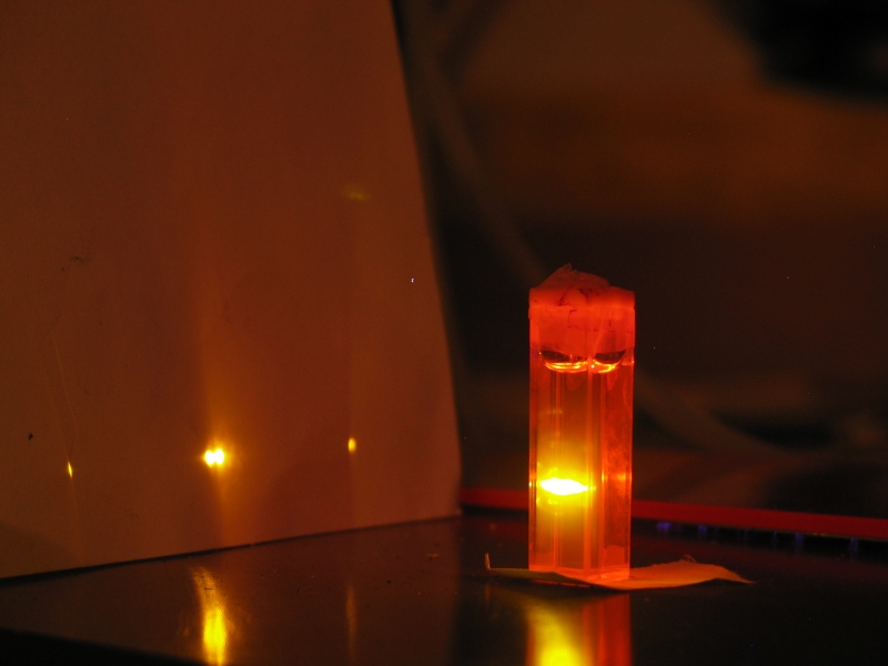
(The following afternoon, Sunday, 17 July, 2005)
Not only does it work at 20 kV, it is again noticeably
brighter, and it easily lases a very old cuvette of
not very pure Fluorescein in drugstore 91% isopropanol,
using the cuvette walls as mirrors (and also producing
a certain amount of superfluorescence). I’m generally
pleased, though the fact that I have to bring it up
nearly to full voltage before it thresholds the cuvette
tells me that I am getting only modest power from it.
OTOH, it is a very ancient sample, and I should
try this again with fresh dye solution.
(That night)
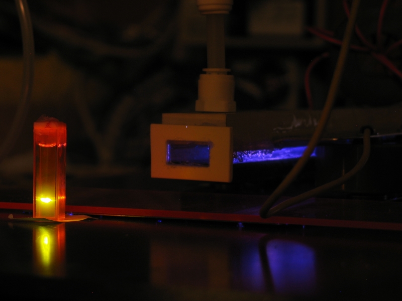
It works quite nicely. Here is a photo showing the
end of the laser and a dye cuvette with fresh Rhodamine
6G:
(The focusing mirror is outside the frame, so you
can’t see it in this photo.)
Here is the unfocused output, on a piece of green
fluorescent plastic. My apologies for the scratches.
(This is a crop; the largest size that’s available
is the 1026x768 that you get if you click the little one.)
I have now swapped out the 780-pf MuRata caps, and
there are 6 TDK caps on each side of the laser. I’m
using 2x 200 pf, in series, as a start cap on the
GP-70. (The start cap does not seem to be absolutely
necessary in this application; it gives me about 5%
increment in pulse energy.) Here are two photos:
Operation is considerably improved; the laser now
thresholds around 12,400 volts, even with the gas mix
not particularly optimized. The output at high voltages
is significantly improved. This seems to be mostly an
issue of more energy storage, and perhaps the lower
ESL of the TDK caps as opposed to the MuRatas, which
have much smaller terminations.
Here’s a photo of a dye cuvette being pumped, with
the laser running at 20 kV and the gas mix partly
optimized:
I think the cloudy brightness around the central
double dot on the paper is superfluorescent lasing.
(23 and 24 July, 2005)
To take these next two photos, I first put a conductive
screen in front of a fast avalanche photodiode (Motorola
MRD500, very kindly furnished by Howard Davidson) and a
ferrite collar on its power supply wires (also a 100-pf
capacitor across the plug at the photodiode end, as a bit
of a bypass). Then I aimed the laser into a diffuse reflector
(a brushed-finish steel sheet), and put the photodetector
into the reflected beam, which was considerably attenuated.
The output of the detector went into the vertical amp of
the scope, which was set to 1V/division.
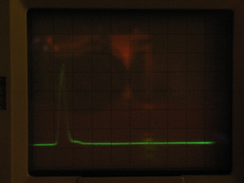
Here is a set of 24 shots (during a 10-second exposure),
on a Tek 7904 oscilloscope with a 7A29 vertical plugin.
The photodetector (which is biased at about 50 V) has
1 nsec or better risetime, and the plugin is rated to
1 GHz; but the 7904 mainframe is only rated at 500 MHz,
so even if this wasn’t a multiple exposure we might
have lost some fine structure if there was any to lose.
I had the camera set to ISO 200, because the scope is not
as bright as I’d like, which is also why I had to
fire the laser so many times; at least this shows the very
reasonable shot-to-shot repeatbility. The FWHM pulsewidth
is probably about 5 nsec. (We’re looking at 10 nsec
per box here.)
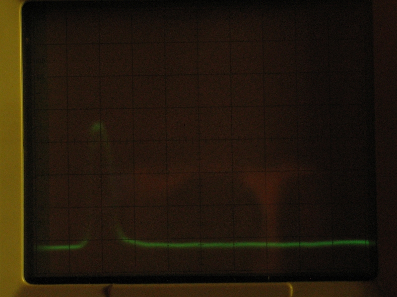
Here is a set of 25 shots (also during a 10-second
exposure, and also at ISO 200), showing what happens
when I put a mirror on the output end of the laser:
Notice that the peak is broader and has a slightly
flatter top. (The decreased height is an artifact.)
I think the FWHM is about 7 nsec.
I rebuilt my little instrumentation amp last night, using
half of an INA2141UA chip (set to multiply x100), and used
it to measure the laser’s output energy with one of
our Scientech heads. To do this, I run the output of the
Scientech head into the amp, and the output of the amp into
the scope; then I pulse the laser (twice a second for the
measurements I made this afternoon and yesterday evening)
for about a minute, which is long enough for the trace to
stabilize, and I note the level. When I stop pulsing the
laser, the trace returns slowly to its baseline.
Then I connect a power supply to the calibration resistor
(~40.8 ohms) that Scientech thoughtfully provided when
they built the head, and bring the scope trace to the
same level. This took 236 millivolts earlier today,
which tells me that the laser was putting out a little
over 1.3 milliwatts. Because I’m pulsing the laser
twice a second, however, I have to divide by 2 to get
the per-pulse energy. The laser is, then, putting out
roughly 680 µjoule per pulse, with the gas mix
vaguely optimized.
Because the pulsewidth is 5 or 6 nsec, that amounts to
a little over 100 kW average power during the pulse, or
perhaps 125 kW peak (if the shape were cleanly sinusoidal
I’d suggest 140 kW peak), which is respectable for
a small laser. If any of the beam is missing the active
surface of the detector (which is possible), then the
energy and power are, of course, correspondingly higher.
I would be happier if the energy were at least 1 millijoule;
but there may be further optimizations.
If I put a reflector in front of the laser, for example,
the measured energy goes up to 740 µjoules per pulse.
(This is entirely consonant with the increase in pulsewidth
that is visible in the photo above.) I do not know the
reflectance of the mirror I used for this test, btw, as
it is not specified at 337.1 nm, but I suspect that it is
not particularly high.
At this point, it’s time to return to the original
intent of this project, which was to design and build a
truly high-performance nitrogen laser.
To the first page in this set, a general discussion
of the issues involved in designing and building a
high-performance nitrogen laser
To the previous page,
which is about my initial effort to produce a
high-performance nitrogen laser
To a “How-To” page
about the laser described on this page
To an interim page about my effort to scale up a published design
in order to enhance its performance
To a page about my recent (starting mid-August, 2006)
redesign of the “DKDIY” laser,
which resulted in significantly enhanced performance
To a brief “How-To” page
about building the revised design
To a page about my current (late 2006) effort to build
a less-expensive laser with even better performance
To the Joss Research Institute Website
To my current research homepage
My email address is a@b.com, where a is my first name
(jon, only 3 letters, no “h”), and b is joss.
My phone number is +1 240 604 4495.
Last modified: Wed May 10 14:42:35 EDT 2017
Testing, Testing
Another Day, Another Channel
More Capacitors:
Energy and Power Measurements
This work was supported by
the Joss Research Institute
Contact Information: