(07 June, 2005, et seq.)
Having developed (we hope) some understanding of the characteristics of high-performance nitrogen lasers, I am now honor-bound to put these principles into practice, to find out how well I actually understand the issues involved. Here, I have lucked out a bit: I’ve been permitted to take down a commercial TEA CO2 laser, the head from which is, or at least should be, a very nice testbed for some of what I’ve described on the previous page.
This head uses a discharge channel roughly an inch and a half across, probably an inch high, and 24 inches long. That’s not quite as big as I’d really like (I’d prefer about 30 inch active length), but it’s certainly large enough for some “proof of principle” testing. This laser is preionized by pin discharges that charge the “peakers”. The main storage capacitor was 130 nf; that’s larger than I’m looking for, so I’m not going to use it. The peakers were (see below) 25 x 470 nf doorknobs, totalling 11.5 nf, a bit less than 10% of the size of the main store, probably fairly reasonable for preionization.
I intend to change that balance somewhat.
Before we move to photos, here’s an ASCII-pic approximation of the configuration:
                -----                             -----
               | 13x |+-+                     +-+| 12x |
              +|470pf|| +                     + ||470pf|+
              ||_____|| |       CATHODE       | ||_____||
              |       | +---------------------+ |       |
              |       +-------------------------+       |
              |             \_____________/             |
              |                                         |
              V                                         V

              A                                         A
              |              _____________              |
              |             /             \             |
        +-----+-----------------------------------------+-----+
        |_____________________________________________________|
                                 ANODE
There is a bolted strap connecting the “U” channel to the negative terminal of the storage cap. That, unfortunately, begins to appear (as of June 13th) to be the major weak point of the design: it isn’t an issue for CO2, but the inductance of the connection may be too high for this laser to work well with nitrogen.
The bottom plate is mounted on stands above the floor of the box (you’ll see why in a moment), and the cathode of the thyratron was electrically connected to the wall of the box at one end, near the shelf that the laser channel sits on. I’m probably going to refine that a bit, but not immediately — it’s not anywhere near as slow as it might be. I am, however, going to change from thyratron switching to spark gap switching, for convenience.
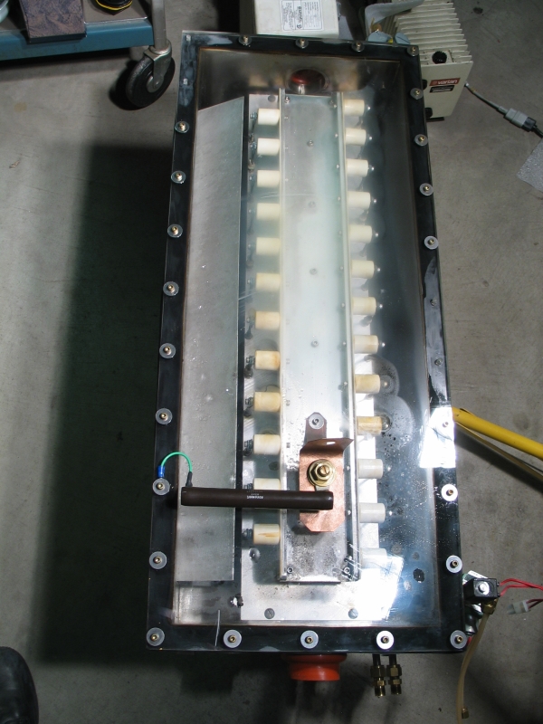
The first photo shows the head with its cover still on. We are looking at it from the “max ref” end; the 100-Ω charging resistor is in the foreground. You can see some water drops inside. If you count, you will find that there are 12 doorknob caps on the left side, and 13 on the right. [Note: if you click any of the small photos, you will get an 800-x-600-px enlargement. If you want more detail, change the “.8c.” or “.c8.” in the filename to “.22c.” or “.c22.” as appropriate.]
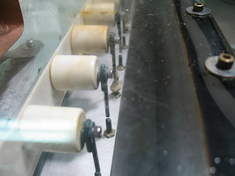
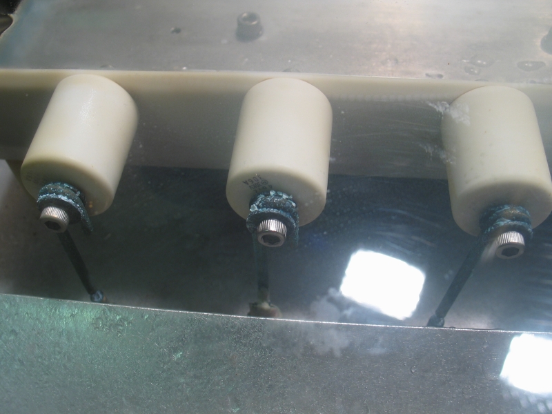
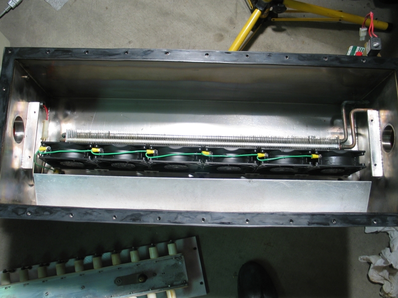
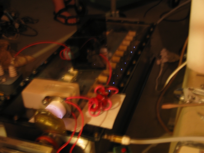
The next three photos show the pin-gaps and some corrosion at the connections to the peakers, and then the channel sitting on top of the head box after I pulled it to dry it off. Turns out that it sits on ledges that are welded to the wall, as you can see in the photo. As I mentioned above, this keeps the inductance of the switch connection fairly low.
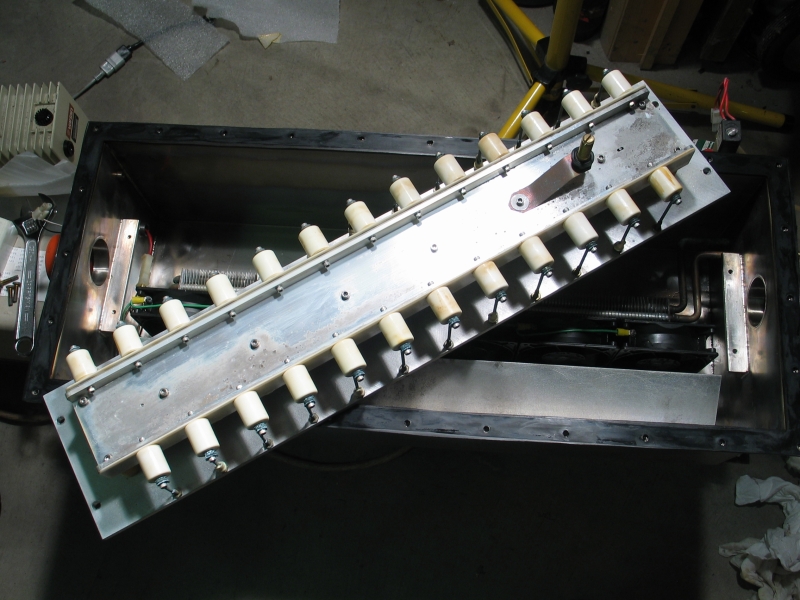
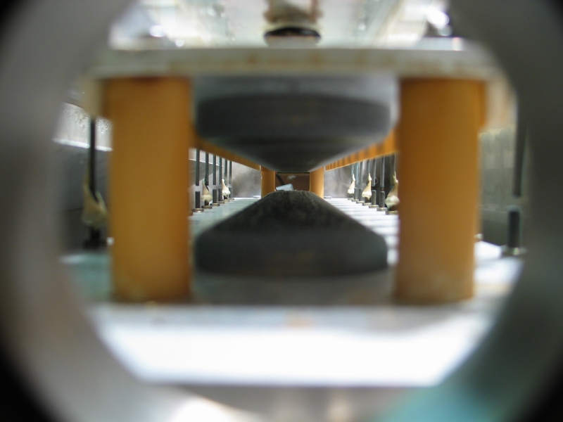
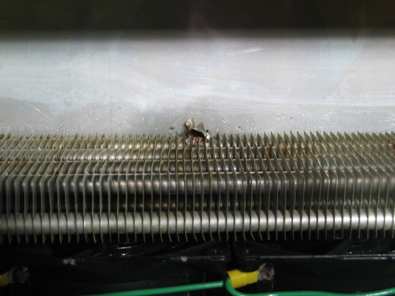
The next three show the view down the channel from one end (taken before I yanked the channel out of the head box); the six [dead] fans that used to circulate the gas through the head; and the blowout in the cooling tube of the heat exchanger. (There is another rupture, external to the head, in a small radiator that I removed before I took any of these photos.)
The optics are (ahem) no longer viable:
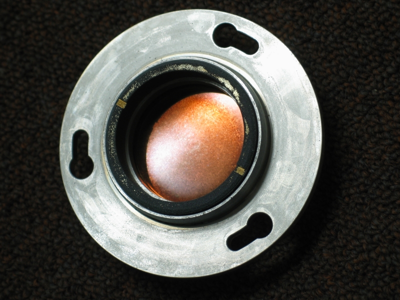
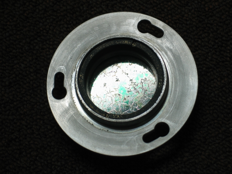
(That’s the copper max-ref rear reflector on the left, and a coated Si or Ge output coupler on the right. Sigh. Not, mind you, that these would do me any good with N2, but it’s a shame to see stuff ruined.)
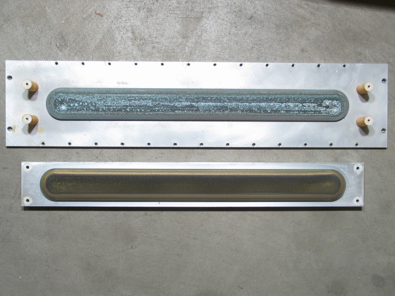
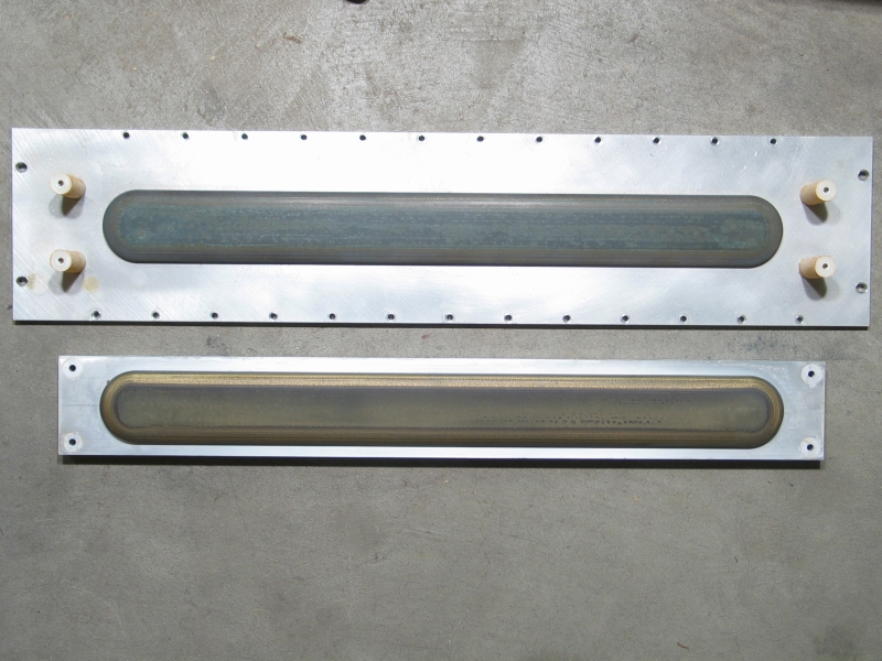
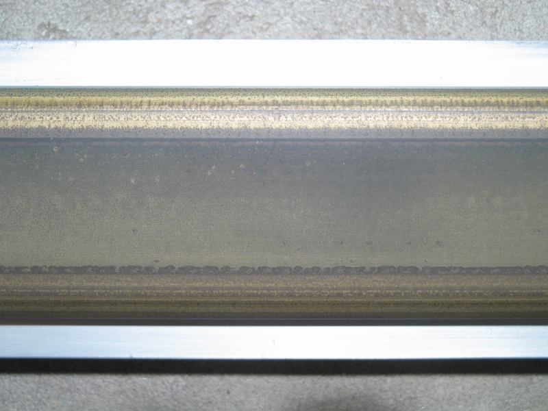
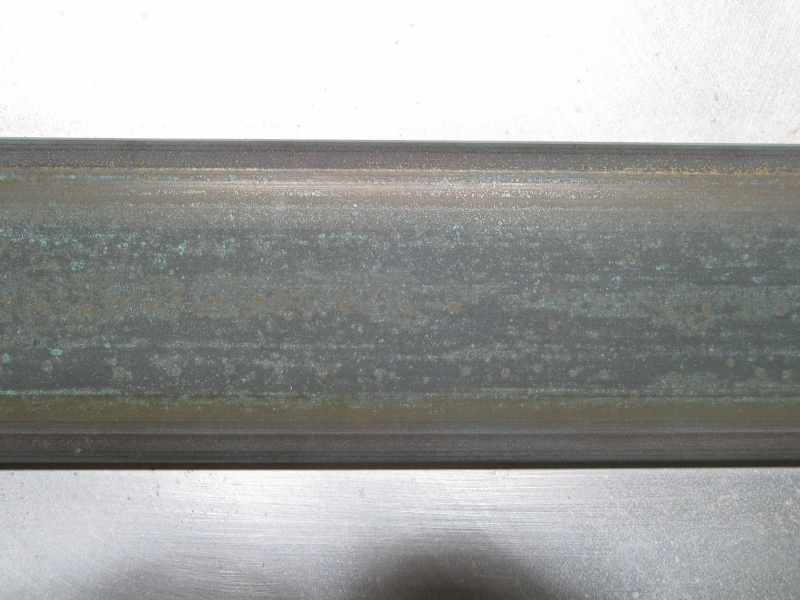
Here are the electrodes as they were when I disassembled the head, and after I rubbed them down with steel wool. (The lower pair are detail views of the anode and cathode after the steelwool.)
When the switch closes, which takes 40 or 50 nsec with a thyratron, a large positive voltage begins to show up on the anode. When this voltage gets big enough, the little pin gaps arc over (because they are narrow, and thus provide an easy path for current), which puts a lot of UV and perhaps some ions into the laser channel. As the pin gaps continue to arc, the current through them charges up the doorknob caps. At some point the voltage across the channel is large enough to start a discharge in it, and after that it’s a question of how much energy is stored in the peaker and dumper caps, how long it takes to discharge, what’s in the gas mix, and what kinds of optics are in place.
In a nitrogen laser, the peakers are more important to
this, and the dumper contributes much less to the laser.
(In a high-pressure nitrogen laser, the dumper is only
there to make sure the peakers get charged; it is too
slow to have much [if any] significant direct effect on
lasing. In fact, a transmission-line head is a good idea
in a TEA nitrogen laser. That, however, is neither here
nor there, as this head will not be operated as a TEA N2
laser.)
My first step (aside from getting out a spark gap) is to reduce the storage cap to 6.3 nf, which I happen to have. This entirely changes the balance: the doorknobs will actually function as peakers. It also provides an opportunity for scaling, which I will discuss in a few paragraphs.
(Note, added on 12 June: When I did that, I had misread the one peaker on which I could see numbers, and I thought they were all 100 pf each. The result was a peculiar imbalance in which the dumper was smaller than the total of the peakers.)
Here’s what I expect:
                      +-+                     +-+
                      | |                     | |
                      | |       CATHODE       | |
                      | +---------------------+ |
                      +-------------------------+
                        |    N \_______/ N    |
                      -----  N           N  -----
                     | 13x | N           N | 12x |
                     |900pf| N           N |900pf|
                     |     | N           N |     |
                      -----  N  _______  N  -----
                        |    N /       \ N    |
        +---------------+---------------------+---------------+
        |_____________________________________________________|
                                 ANODE
(This is not drawn to scale.)
I’ve actually incorporated two sets of changes into this diagram. First, the structures that look like towers of “N”s are preionizer boards made of polycarbonate plastic, each of which has carborundum grit epoxied to its inner face. This not only reduces the inductance of the secondary (“peaker”) circuit, but also lets me test a form of semiconductor preionization. Unfortunately, careful inspection reveals that the U-channel is not wide enough for the caps to fit under it; I may find a way to extend it out to the sides.
Second, I have indicated the doorknobs as 900 pf each here, which is part of the scaling I suggested earlier — it goes along with using a 60-nf Maxwell as the “dumper” cap. This is roughly a 10X increase in total stored energy, and it should provide a 5-to-10X increase in output power and energy, in addition to causing the pulsewidth to increase beyond 8 nsec. It would also let me tweak the anode-to-cathode spacing.
Even if semiconductor preionization doesn’t work, I may still be able to keep the capacitors in this configuration (if I can get them into this configuration at all) by going to DC preionization. Again, that would permit me to adjust the anode-to-cathode spacing to some extent.
One way I could provide a low-inductance cathode connection and simultaneously address the issue of placing the peaker caps would be to ram 24 or 48 pins through the lid, and replace the cathode with a mesh. Preionization takes place behind the cathode, by arcs from the pins, rather than off to the side. It’s tempting.
We Shall See how all of this works out, if I can make it
work at all.
(10 June, 2005)
Having verified that the fan bar is indeed totally kaput, I emptied it and reconstructed it, using two fans I had in my junkbox and the fan from the heatsink for the thyratron that used to operate this head. (The heatsink, a little radiator, also has ruptured tubing and is no longer viable, so I didn’t feel too bad about taking the fan from it.)
The reconstructed fan bar is now in the head, and has been verified to work. Next step: electrical connections for the HV, and emplacement of HV components. I have a foil that will connect the spark gap to the box, I have the spark gap connected to the capacitor (a small Maxwell of 6.3 nf and 18 nh ESL), and I need to work out the connection between the capacitor and the cathode, as the existing bracket is made to fit a much larger cap. I also need to work out the connection between the foil at the box and the spark gap; the box end of it is ready to fly, but the switch end is not.
Next up after that is gas. I need to be able to fill the laser with helium, I need to be able to add nitrogen, and I need to keep leakage down to a dull roar.
I’ve already pulled the optical resonator structure out of the large box, but of course I don’t really have any optics for it. I’m going to use a fused silica lens of low quality as an output coupler, as it is on hand; I may just block off the other end of the laser for now, so that I can test at all — I think the lens is the only 2" optic I’ve got.
(My luck, the mounts will turn out to require 48 mm or something like that, and the lens won’t fit... well, We Shall See.)
[Some minutes later...] Sure enough, it’s even worse: the mounts take 50 mm optics, and the silica lens is 2¼ inches across. After a bit of thought, I have put the lens directly into the rubber hose that is supposed to connect one end of the head with its mount, and gently tightened the hose clamp around it... a strictly temporary lashup, but at least it will let me see what’s going on in there. (You can see this hose at the bottom of the first photo.)
Next, I will see if I can get a 50-mm circle cut from a piece of front-surface mirror that I have here... (The local glass and mirror shop was just closing, but I left a piece of FS mirror with them, with a request that they hack a 1&15/16" circle out of it. They’ll check with their glass manipulator person on Monday to see if he thinks he can do it.)
At this point (about 5:30 on Friday evening), I am perhaps only 4 or 5 hours away from a first test. (I hope.) First, however, I think maybe I’ll go get some dinner...
[Some hours later...] I have now buttoned up the head,
connected the spark gap and capacitor, made a rude and
temporary max-ref reflector (which I’m attaching to the
front of the dead copper mirror with RTV), and completed
the gas fittings. Once the RTV has set and I’ve attached
the HV and trigger, I can try running this thing. I half
expect that it will just discharge across the outsides
of the doorknobs, but we’ll cross that bridge when it
burns under us.
(11 June, 2005)
Having completed preparations, I started testing. It took a while for the preionizer sparks to change from white to pink, and until that started we didn’t see any discharge in the channel; I am guessing that we were discharging through the 100-Ω charging resistor that connects the negative side of the main store to the box. Eventually, as the preionizer sparks continued to change color, we started to see a beautiful glow discharge in the laser channel. No lasing, mind you, but at least it’s clear that the preionization technique works. (For safety I viewed the channel through a dark red filter, even though we were unable to see any fluorescence from several “day-glo” or optically brightened materials.)
Adding nitrogen changed the color of the discharge somewhat, and adding too much nitrogen made it first get thin, and then go away.
We took a break, and I thought about this for a while. It was possible that the output lens wasn’t fused silica, and that we actually were getting lasing but just couldn’t see it; we later disproved that by removing it and testing it directly with a mid-wave UV lamp. It’s fused silica. In any case, the channel has fairly large volume, and it occurred to me that perhaps we just weren’t reaching threshold, so I decided to try a larger main store.
With a 30-nf Maxwell (20 nh ESL) in place, we got a bit more UV out, but not enough to make me think that we had a laser on our hands. Milan Karakas points out that He has a nice strong line at 388.8 nm, which was probably the source of most (if not all) of the UV we were getting out of the device.
I’m not really sure what to make of this. Perhaps
the next step is to put larger peaker caps in: if I go
from 2.5 nf total to 12.5 nf, perhaps that will change
the character of what’s going on in there. [NOTE:
I wrote that when I still thought that the peakers were
only 100 pf apiece.] OTOH, I have some suspicion that
the plastic protectors on the edges of the U-channel
have holes that are too small to permit the attachment
of low-inductance doorknobs, which is somewhat
annoying. OTTH, if I can get the voltage on the
discharge high enough, that may not be as much of an
issue because the pulse should lengthen somewhat. OTFH,
the inductance of the cathode connection to the negative
side of the dumper cap may be so high as to prevent the
channel from ever developing enough voltage to lase
nitrogen. (That, however, seems somewhat unlikely, in
view of the fact that various other lasers have
generated at least some output even with extra
inductance added for testing purposes.)
Later, that same evening...
I tried argon. Not only don’t I get any lasing, I don’t even get a discharge in the channel. I am left to wonder where all the energy from the dumper is going. The pin-gap sparks were certainly bright enough!
I think I’m going to change the peakers to 780 pf; I believe I have 25 of them, which is just right, and they are even the correct size. That will give me a better balance with the 30 nf dumper, and we’ll see how it goes. If there is still no joy in Mudville, I will proceed to make a low-inductance connection to the cathode, to replace the 3/8" bolt that now penetrates the lid of the head. That will be annoying, but I hope it will make a real difference in the way this head operates.
In the meanwhile, here are a few more photos. The first is a handheld 1-second exposure that shows a few of the pingaps (and also the glow inside the spark gap); it was taken with the 6.3 nf cap still in place. I believe that this was taken with helium in the chamber, but don’t trust my memory.
The second is a view down the side of the head, to give you a sense of the pingap locations in the third, which was taken with argon in the channel and the 30 nf dumper in place.
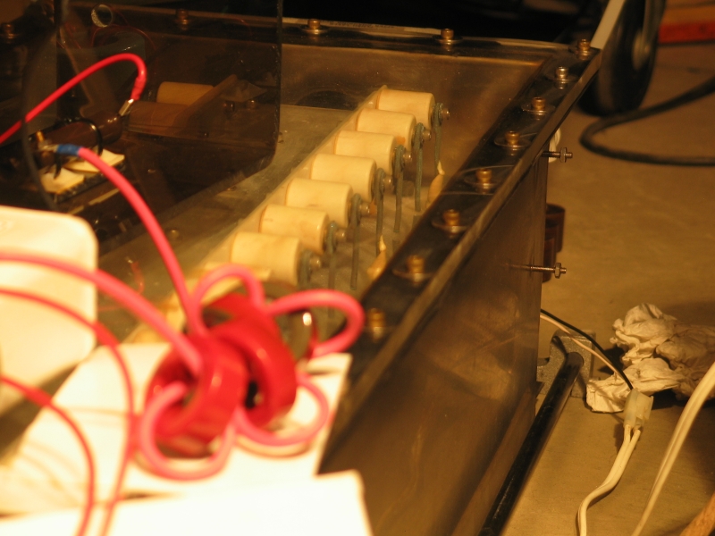
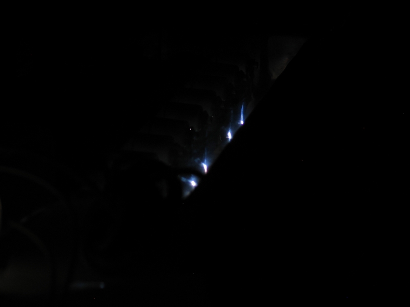
Unfortunately, only a few of the pingaps were visible from that angle, and the camera’s view of two of them was blocked by the epoxy or ceramic standoffs that are glued to them. (This material is vaguely visible in the middle photo. The gap farthest from us [which we’ll call #1] and gap #4 are the ones that are blocked by standoffs.)
I tried, during the afternoon, to take a photo of the glow in the channel, but failed. It wasn’t very bright, and I need to catch more than one discharge in order to capture it.
If we don’t have enough E/p, it won’t matter how much current we ram through the discharge — the thing still won’t lase if it isn’t pumping the nitrogen to the upper laser level. This is part of what leads me to believe that I need to make a lower-inductance connection to the cathode: I’ll get more voltage across the channel before it breaks down and discharges. (There will be more about this issue, later.)
OTOH, that’s going to be a real pain in the neck. The
foil has to attach to the U-channel, but even so I have
to be able to remove the lid from the head, and I can’t
tolerate leaks so I can’t leave the slot for the foil
unsealed. I may have to make a rectangular slot in
the lid, make the slot for the foil in the piece I cut
out, and gasket the piece back in. When I need to take
the lid off, I undo the gasket cover and the gasket,
leaving the foil still attached to the cathode and to
the rectangular piece of lid that fits into the cutout.
Painful, but maybe viable. We’ll see... (There will
be more about this issue later, as well.)
(12 June, 2005)
This evening I took the cover off the box, removed all of the peaker caps (discovering, in the process, that they are 460 or 470 pf), cleaned up the connections to the pins, and reassembled with the two dozen (argh) 780 pf caps I found and one 500-pf cap. Extremely annoying. I have purchased 10 more 780-pf caps on eBay.
Also annoying, in the process of doing this, I also discovered that the thickness of the plastic plates along the sides of the U-channel is about twice the distance that the electrodes extend out from the ends of the doorknobs. The inner ends of all of the old peakers are gray and appear slightly corroded.
(There is a precept about nitrogen lasers that I want to state rather explicitly here: Optimize whenever and wherever possible, because every little bit helps. The people who made this laser had no intention of running it with nitrogen, so they were operating with different precepts, and I must now correct.
I am not going to close up the head again until I figure out how to make nice tight connections from the ends of the doorknobs to the U-channel. There are two obvious possibilities: washers (very difficult to find the right size; I could conceivably use a single turn of copper wire, if I can fabricate 25 pieces) or different plastic. I’m going to look for some copper wire of a reasonable diameter first....
Ahh, the joys of the scrapheap and the toolbox: after some fruitless searching (I have 12 gauge, which is too thick, and 22 gauge or so, which is too thin; stranded would fall apart, so that won’t do either ...grrr), it occurred to me that copper mesh would be optimal. I went into the electronics toolbox and found some fairly heavy gauge desoldering wick. Just the thing! A circle of this around each screw, compressed, should make reasonable contact. It even provides a teeny bit of shock absorption, in a physical "tremor" sense.
Having reassembled the device, I tried it again. This time the glow on fluorescent objects is significantly brighter, but there is no compelling reason to think that it’s lasing.
Sigh.
At any rate, we’re getting closer. Milan Karakas points
out that the original design voltage was >30 kV, and that the
CO2 mix isn’t all that much different from a
mixture of N2 and He. I suspect that he is entirely correct, and
I think my next step is to "pump up the volume". In doing that,
I may also switch to the 60 nf capacitor as main store, for
two reasons: 1) it has slightly lower inductance; 2) it is
rated for higher voltage than the 30 nf cap I’m using now,
which is only good to about 35 kV max.
(Later that evening...)
I have now got the laser on the optical bench, and I’ve swapped out the small spark gap for a GP-15B, which can handle up to 36 kV in open air. I’m not running it that high, though, because I still have the 30 nf capacitor in place.
So far, no lasing; but I have reasonable discharge in the channel, and I have vague hopes. I suspect that it is important to get the air out of the head, and it takes quite a bit of helium to do that. I’ve just added a bit of nitrogen, and it’s mixing as I write this...
...And, as luck would have it, my TM-11 trigger unit blew up even though I had it capacitively isolated and one side of the output was grounded to the case. I noticed the power light blinking brighter on one or two pulses, looked at it, clicked the trigger switch one more time, and got to see a puff of smoke from the light as the breaker tripped. It didn’t blow its own fuse; it didn’t trip the little breaker on the power strip I had it plugged into; no, it tripped the breaker in the power panel, many yards away. Argh.
I did think I noticed that the light from the discharge wasn’t as bright during that set of pulses as it had been earlier, which could argue that I had too much nitrogen in the head. OTOH, I could be fooling myself. In any case, I don’t really think I’ve seen lasing at any point during this exercise.
If I can develop as much as 8 kV across the channel before it begins to conduct, a mere 32 Torr of N2 should get me reasonable lasing with 25 mm spacing between the anode and cathode; this argues that I’m not developing even that much voltage in there. I am at a loss to explain why this should be the case. Sure, it’s easy to make helium conduct, but various articles report that helium didn’t seem to give them any trouble, and in fact they seem to find that it improves discharge quality and shot-to-shot uniformity.
Something isn’t quite right, and I’m blasted if I know what it is. The one thing I haven’t really tweaked is the inductance of the connection from the negative pole of the main store to the cathode of the laser. That does represent a weak point in the design, and perhaps I should do something about it when there’s time and I have a working trigger unit... argh.
When I opened up the TM-11, I was pleased to discover that what had happened was merely that the power indicator light had blown up. It had a little hole in the side of the sleeve that contains it, and there was a blackish smoke-stain on the inside of the case next to it. I removed the light, and left the cover off the unit when I put it back on the bench. When I fired the laser, I saw a spark inside the trigger unit, at the power switch; I remembered seeing sparks from the case to the bench on previous occasions (it’s sitting on half an inch of epoxy/fiberglass composite now, to prevent precisely that), so I grounded it directly to the bench with a short wire. End of issue; it just works now.
My plan to examine the optical pulse, however, isn’t
working at the moment: I need to put my photodiode and
its power supply inside a Faraday cage. The electrical
noise in the room when I fire the laser is completely
overpowering the signal. Sigh...
(evening of 14 June and morning of 15 June, 2005)
Milan Karakas has pointed out that it takes a large amount of current to sustain a discharge in such a big channel (about 36 cubic inches). That’s very true; it is possible that the voltage on the peaker caps drops so rapidly as the channel breaks over that they never pump enough nitrogen to make a significant difference. There are several possible ways to deal with this. I expect that my first experiment, suggested by Milan, will be to make the electrodes effectively narrower. Milan’s original suggestion was to cover the edges of the anode with glass, so that only the center was exposed. I should be able to do that, but it would be difficult and complex (I’d have to build a large structure from microscope slides and pieces of plastic), so I’ve come up with something simpler: I think I will put a 24-inch-long metal rod on top of the middle of the anode. Not only will that make the anode effectively narrower, it will also reduce the channel spacing. I don’t even have to glue it into place — the mere fact that it is there will be enough for a quick experiment. If I can get any lasing at all, it answers several questions. If not, I’m not sure what I’ll do next. Depends on why not.
[Well, I tried it. Turns out that unless I use an extremely limp metal bar, it makes contact only in a few places, and as a result I always get bright sparks instead of a smooth glow. I’d have to tack it down with some sort of conductive glue in order to get good conductivity everywhere, and even that wouldn’t guarantee a smooth discharge in the channel. It was worth a shot, I guess, but I’m either going to have to try something closer to Milan’s original proposal or abandon this testing path.]
One thing that’s quite likely: rather than running a broad foil through the lid, I am considering a different approach:
                                  HHH
                                   N
___________________________________N_________________________________
                                   N
___________________________________N_________________________________
                                   N
                                   N
                                   0
                      - -+- - - - - - - - - -+- -
                       -----               -----
                      | 13x |             | 12x |
                      |900pf|             |900pf|
                      |     |   _______   |     |
                       -----   /       \   -----
        +----------------+-------------------+---------------+
        |____________________________________________________|
                                 ANODE
Here I have a number of bolts coming down through the Lexan lid of the box; they have rounded ends. These are placed a short distance above a sheet of perforated metal, which serves as the cathode. Because they are threaded, the distance is easy to adjust. All of the bolts connect (on top of the lid) to a broad foil that goes to the negative terminal of the capacitor. Any one bolt wouldn’t provide enough current to charge the peakers very quickly, but I’m hoping that 33 of them (that’s one every ¾") will.
Because the bolts are all in a single line, this configuration will create a narrower discharge, though it may increase the channel spacing slightly because of the height of the doorknobs. (The 900-pf ones are bigger than the ones I’m currently using.) It also should decrease the inductance of the peaker section significantly: it puts the peakers closer to the channel and connects them more directly to it; in addition, the 900-pf caps have broad terminations, so they have lower inherent inductance than the smaller doorknobs, which have terminations that are much more narrow.
I’ve drawn the perforated metal sheet here as a flat piece. I don’t know whether that will work, but there’s a fair chance that it will, as all of the preionization will come through on the centerline. It certainly simplifies the construction.
Adjustment of the bolts not only provides evenly
distributed preionization along the length of the
channel, it may also allow me to adjust the breakdown
voltage of the channel a bit — if the bolts are
farther away from the cathode, more voltage will be
present when they arc to it, and the channel voltage
risetime should be steeper as a result. They can’t be
pulled too far back, but at least some adjustment
will be possible, and I’ll be able to explore this
issue. In the meanwhile, I’m going to construct a smaller
laser to check some design and parameter issues. (See
the next page.)
These are at the end of
my rant about the Scientific American nitrogen laser.
To the next page, about my continuation of this effort, which resulted in a laser that puts out about 100 kW and can operate without a vacuum pump
To a “How-To” page about that laser
To an interim page about my effort to scale up a published design in order to enhance its performance
To a page about my recent (starting mid-August, 2006) redesign of the “DKDIY” laser, which resulted in significantly enhanced performance
To a brief “How-To” page about building the revised design
To a page about my current (late 2006) effort to build a less-expensive laser with even better performance
To the Joss Research Institute Website
To my current research homepage
My email address is a@b.com, where a is my first name (jon, only 3 letters, no “h”), and b is joss.
My phone number is +1 240 604 4495.
Last modified: Wed May 10 14:37:05 EDT 2017