This page presents the design and construction of a nitrogen laser that can be built by a Do-It-Yourselfer. It is a scaled-up version of a smaller and simpler previous design.
The laser is constructed, as much as possible, from materials that are available at hardware stores and hobby shops: plastic “lumber”, aluminum rulers, steel rods, compression fittings, pieces of basswood and spruce, etc. I used a commercial spark gap, but it is eminently feasible to build one. The two items used in this design that are not easy for a do-it-yourselfer to construct are the “doorknob” capacitors, which are available from time to time on eBay; and the fused silica windows, likewise an eBay item, though it is possible to use fused silica microscope slides, which I buy from EMS.
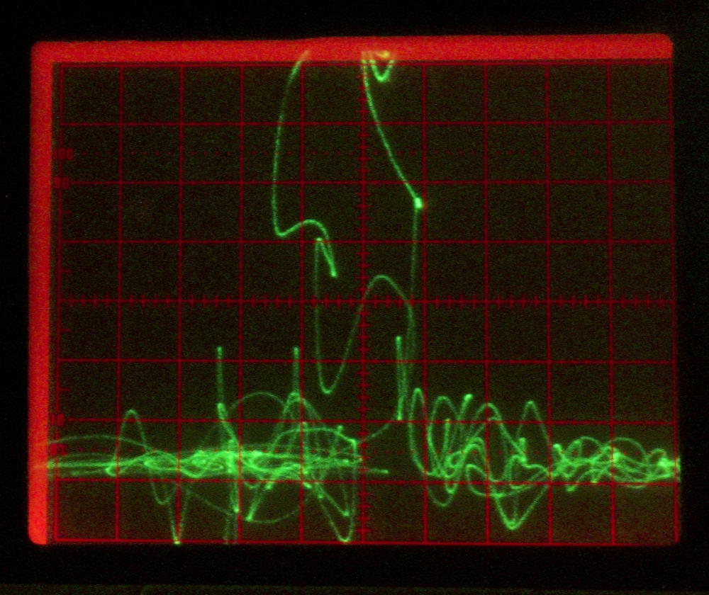
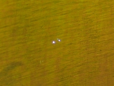
This laser uses either nitrogen or a mixture of nitrogen and helium at low pressure (roughly 30-90 Torr each), runs at 25-30 kV, and puts out pulses of more than 1.6 millijoules, lasting ~8 nsec FWHM. This corresponds to average pulse power of 160 kW and (assuming a vaguely sinusoidal pulse shape) peak power of roughly 230 kW. It is enough power to make small sparks if you focus the beam onto a metal surface:
[For anyone who is reading this before the prototype is
completed & tested, those numbers are placeholders
that I have achieved with the prototype, and will be
replaced by higher numbers when I get the prototype
optimized better.]
Construction and operation of this laser (or any
high-performance pulsed laser, particularly one that
emits output that is invisible) should be attempted only
by people who have been trained to handle lasers and
high voltages. The term “training” includes
relevant and appropriate DIY experience; but if you have
never built a working nitrogen or TEA CO2
laser before, this is not the right place to start. Even
the previous design, referred to above, is a bit difficult
for a beginner.
(30 July, 2005; 4 August, 2005; 7 October, 2005;
May and June and September, 2006; October 2009.)
This laser is intended to operate at reduced pressure,
though there is some chance that it will work with a
full atmosphere of helium inside the head. The channel
is roughly 3 mm deep (the actual depth depends on
discharge parameters, as well as the width of the
electrodes) and about 22 mm wide. It has active length
of about 600 mm, but the electrodes are about 914 mm
long (this may help to reduce the amount of sparking at
the electrode ends). The overall length of the head is
approximately 950 mm.
The switch is an EG&G GP-32B spark gap, which is
rated up to at least 30 kV in air. Although such gaps
are available on eBay from time to time, it is eminently
possible to construct your own triggered spark gap if
you cannot buy one or even simply prefer not to. I must,
however, stress the fact that a triggered gap with low
inductance is almost certainly required for good
performance. Any gap with excessive inductance is (in
the words of an earlier era) unlikely to give
satisfaction.
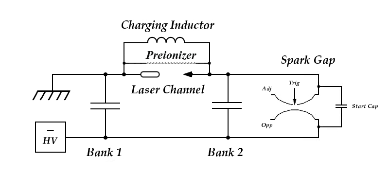
Here is the schematic diagram of the laser:
The preionizer is a coating of 100-mesh silicon carbide powder
embedded in a thin layer of epoxy on the inner surface of the
upper sidewall of the head. It is connected to the electrodes
by steel rods that also serve to space the upper sidewall
away from the electrodes. I have indicated a charging inductor
here, but you may find that a resistor works better; it is a
good idea to try it both ways.
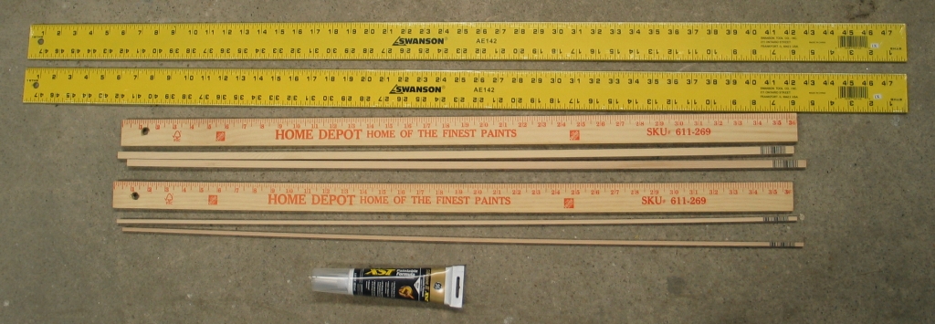
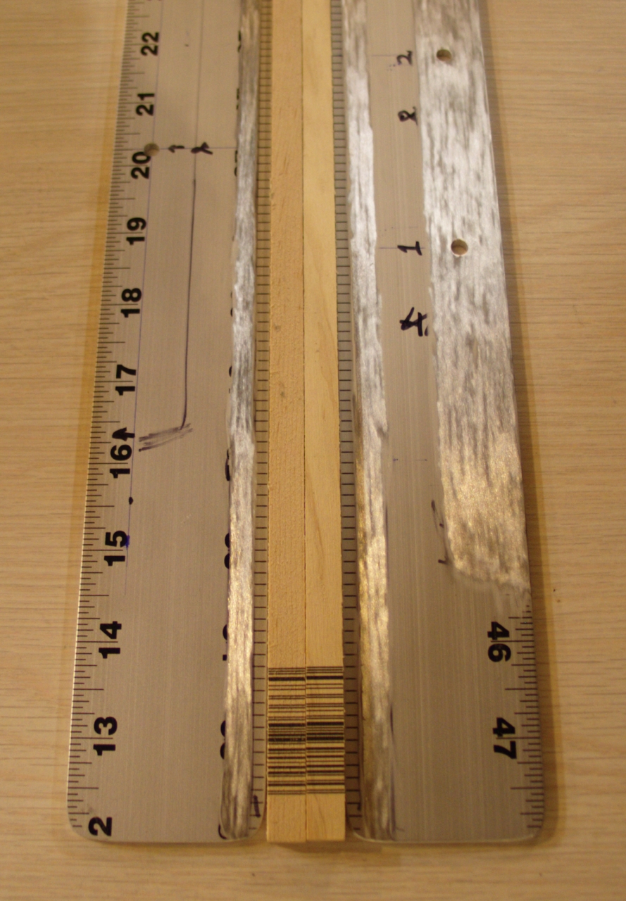
Here are some of the things you will need if you want
to build this laser:
(Two aluminum rulers, 1/8" thick and at least 35" long;
two wooden yardsticks, about an inch and a half wide;
two pieces of spruce from the hobby shop, 3/16" square;
two more pieces of spruce, either 1/4" square or, if you
can’t find that size, 1/4" x 3/8" or even 1/4" x
1/2"; one or more tubes of silicone rubber caulk. I have
found that the “XST” paintable version,
shown in the photo, works better for me than other
versions I’ve tried.)
In addition to what you can see here, you will need a
brass kickplate from the hardware store (I used a large
one, 8" x 34"); 16 laser-grade “doorknob”
capacitors (I used capacitors rated 2000 pf and 40 kV);
some sort of spark gap switch and a trigger circuit to
operate it (I used an EG&G/PerkinElmer GP-32B, which I
got on eBay, but you can certainly make your own gap);
some plastic quick-connects for gas and vacuum (you can
use metal fittings if you can’t find plastic
ones); a pair of fused silica windows; a mirror; some
silicon carbide grit to make a preionizer (unless you
decide to build a more traditional preionizer, a subject
I will try to discuss later, or you can email me if you
have questions); various nuts and bolts; one or two
types of epoxy cement; and a certain amount of
high-voltage insulating varnish. Also, of course,
various hand tools, preferably including a
jeweler’s saw, a high-speed rotary tool, a set of
small files, an X-Acto™ knife or equivalent, and
so on.
Oh, yes: you will also need a high voltage power supply
and a vacuum pump of some sort, if you actually expect
to operate the laser.
Notice that the electrodes are aluminum rulers, which
will be cut down from their original 48" length to
35". These provide both good stiffness and a clean
straight edge, though you have to choose them with
some care — I have seen many bent rulers at
hardware stores during the development of this design.
Even if you choose them well, they may not provide the
optimum edge profile; different researchers have
obtained varying results that seem to depend on obscure
details of design, and it is very difficult to predict
in advance what the optimum edge shape will be. In any
case, it turns out to be important to remove the
anodizing (or paint) from the working edge. Anodizing
creates a tough surface coating, which is difficult to
remove; if you scratch up the edge in the process of
getting it off, you will probably want to polish it
smooth again. You can run through increasingly fine
sandpaper until you get to at least 1,000 grit, which is
available at auto-parts stores, or you can get up to 600
or 800 grit and then either stay with a satin finish, or
rub with fine steel wool. You will need to sand again if
you scratch the edge up in the process of removing
paint or rounding the corners.
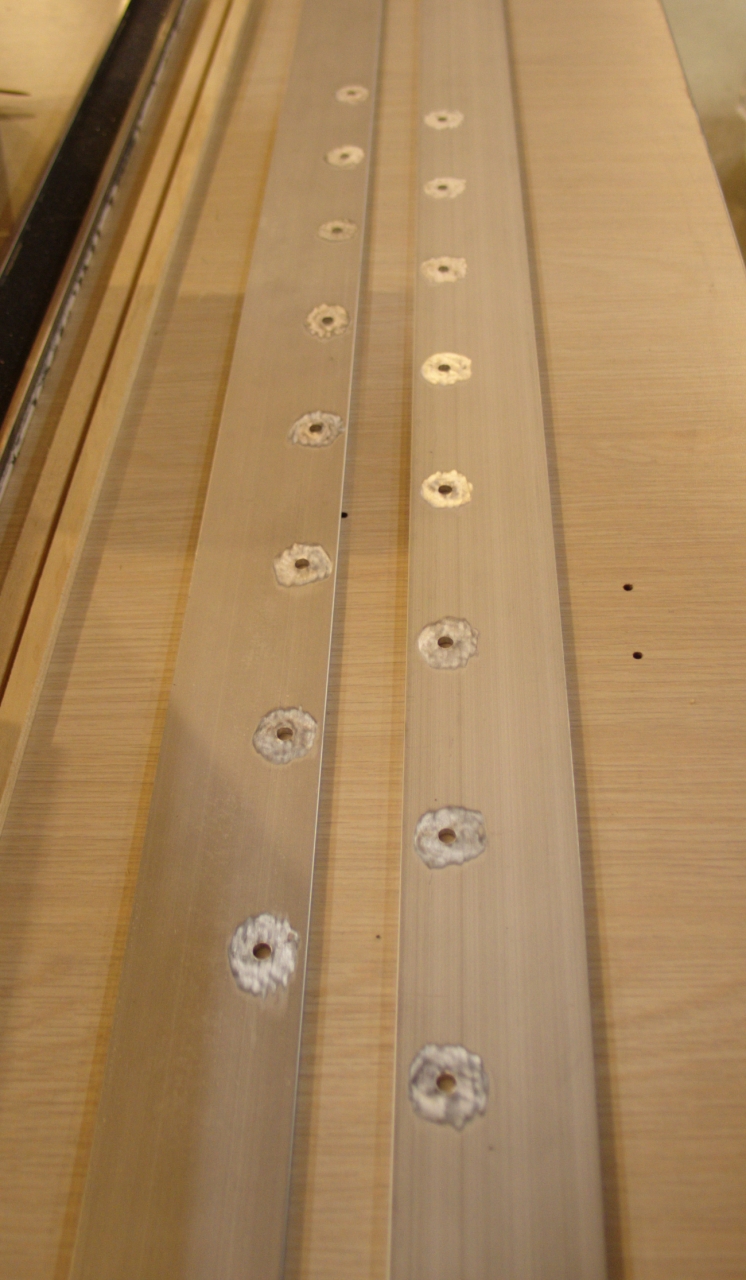
You will also have to remove the paint or anodizing at
the places where the ruler makes contact with the
doorknob capacitors. I used a handheld rotary tool
(there are several common brands, all of which can
rotate quite quickly) with a wire brush wheel. This is
fine for the capacitor contact areas, but I am worried
that it may be too uneven for the edges, so I
didn’t use it there (see photo, when I get a
chance to post it). The paint on these rulers, btw, was
so thick that making the one pair of electrodes used up
the wire brush wheel, and I will have to get another
one.
It is crucially important that you make sure there are
no gaps in whatever sealant you use to attach the
electrodes to the spacers, and the spacers to the
sidewalls. It is impressively difficult to find and seal
all of the leaks in a new head, and sealant gaps just
make things worse. When you have assembled the head, you
should test for vacuum leaks (and fix them, and retest)
before you connect it to the capacitors on the
baseplate — it is a lot easier to reach the
underside with the head unattached. After you have made
sure it is sealed, if you intend to operate the laser at
voltages above about 20 kV, you need to paint
high-voltage insulating varnish on the baseplate
(visible in the photo that I will add when I get a
chance) and on the undersides of the electrodes, to
prevent flashovers. Remember to avoid insulating the
areas where capacitors will be attached (!).
Test the head again after you insulate it and attach it
to the baseplate, as the stresses involved could open
old leaks or create new ones.
Because nitrogen lasers need to be fast (see
my page about the issues involved
if you want more information about this), you should use
broad foils to connect the cathode and the baseplate to
the spark gap switch. It is best to cover the full width
of the doorknob array, but I found that I could get away
with 12" and still achieve reasonable performance. The
switch itself should have the lowest possible inductance,
which means that it should have wide electrodes. I use
commercial spark gaps for convenience, typically EG&G
GP-15B for voltages of at least 25 kV, GP-32B for
voltages of about 15-30 kV, and GP-14B for voltages of
12-24 kV. For smaller lasers, GP-70 gaps are suitable for
12-24 kV. These gaps are currently manufactured by
Perkin-Elmer, and may be sold as either EG&G or PE.
My prototype of this laser used a GP-32B.
Here are some photos of my prototype head, first parts
during construction and then discharge examples. These
are not the least bit optimized, and the examples are
not photos of the final version; my apologies.
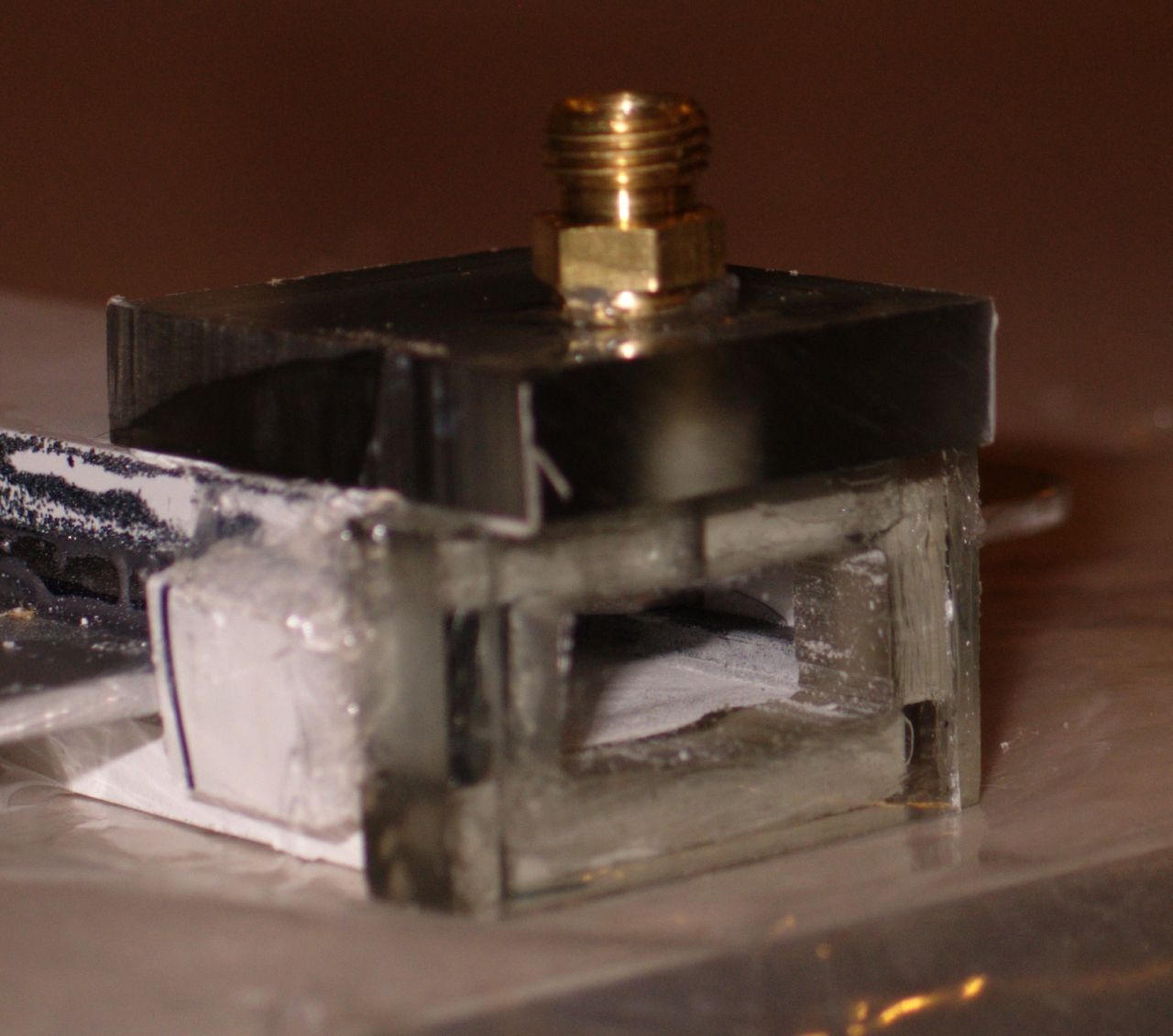
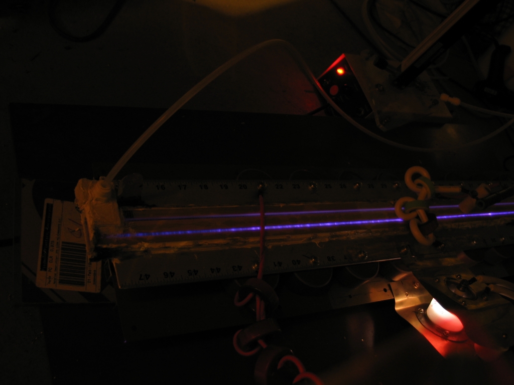
Here is a view of the discharge in the prototype,
before I changed from a glass “roof”
to a wooden one:
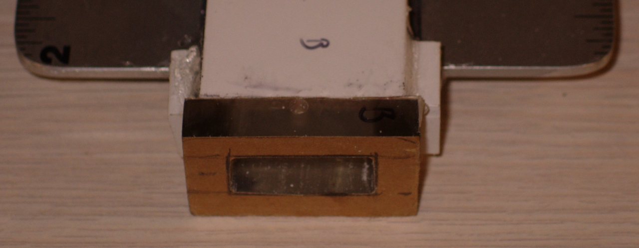
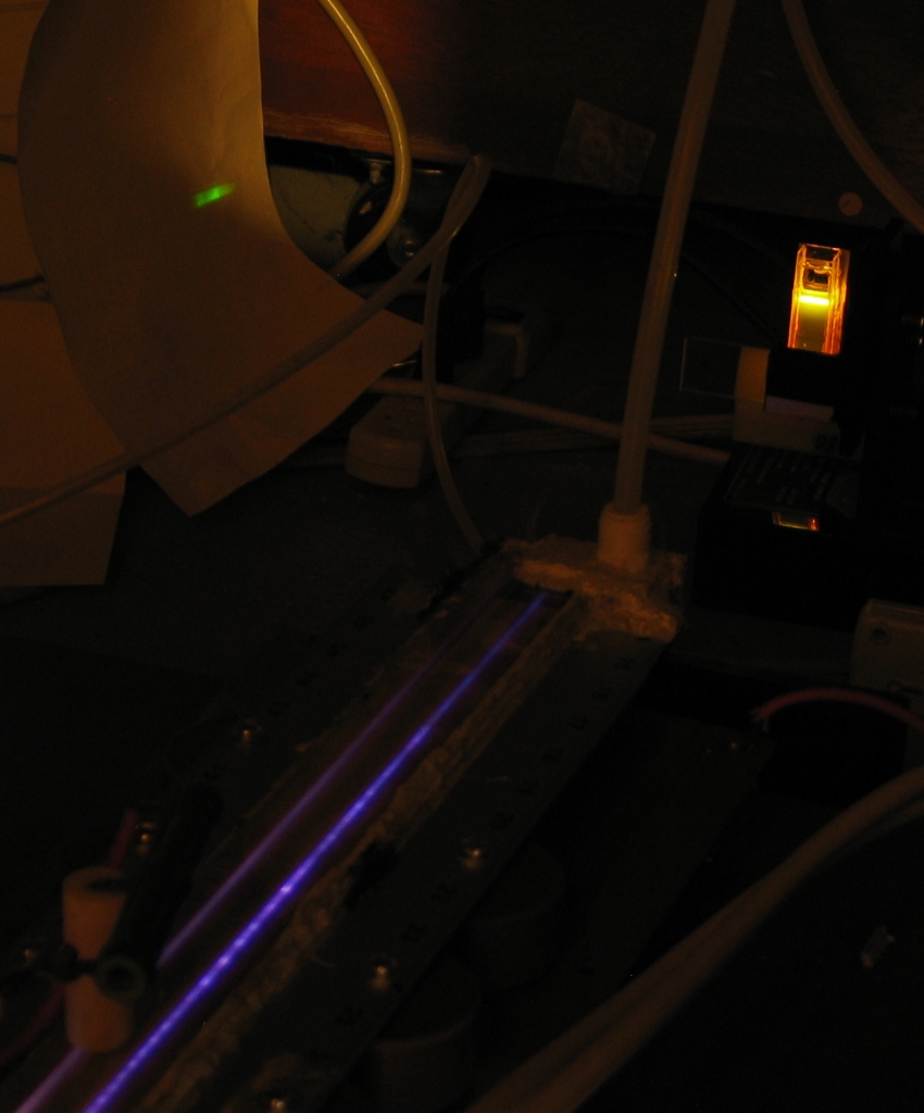
Here is a view of the laser pumping a small dye laser,
using a homemade cuvette:
(Again, this is an earlier version of the prototype,
with considerably less output power than the final
one. Even so, it had no trouble pumping the dye.)
(19 September, 2006)
CAUTION
General Plan
Materials and Construction
Views
Initial Testing