This page presents the design of a nitrogen laser that is intended for DIY construction; it operates with a mixture of helium and nitrogen at room pressure, and uses a mildly novel semiconductor preionization method adapted from other types of laser. Where possible, it uses parts and materials that can be purchased at a hardware store. The device has active length of about 17", and overall length of about 24".
The laser operates at voltages of roughly 12 to 20 kV or perhaps a bit higher; does not require a vacuum pump; and puts out, at full voltage, more than half a millijoule in a pulse that is 5 or 6 nsec long FWHM (Full Width at Half Maximum).
The design is not hard-and-fast, nor is it restrictive. It can be modified at need, or upon desire. It may be scalable, for example, to higher capacitance and/or a longer channel. It may also be possible to switch this laser with a thyratron; thyratrons have much longer turn-on time than spark gaps (several dozen nsec as opposed to 5-15 or so), but the circuit may not be overly sensitive to that issue.
(See also
this page
for a follow-on design that has higher performance.)
(17 July, 2005, et seq.)
[PHOTO NOTE: If you click any of the small photos, you’ll get a bigger one. Most of the larger ones are 800 x 600 px, or 600 x 800 px if they are in portrait orientation. If you want the original pixels from the camera, 2272 x 1704 px, change “.8c.” (or “.c8.”) in the filename to “.22c.” (or “.c22.”). If a full-size original is not available, I will note that fact in the text.]
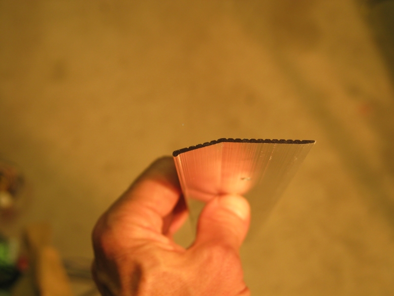
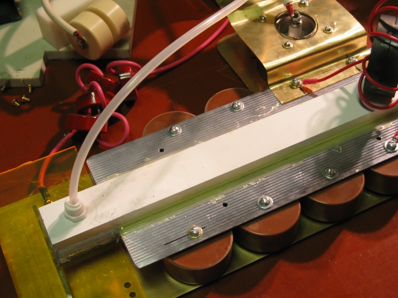
The electrodes of this laser are made from an aluminum extrusion intended for use as a carpet edge protector. A 3-foot piece of this extrusion costs five and a half dollars at the hardware store, which is not too bad. The extrusion has a small cylindrical bulge at one edge, which becomes the actual electrode surface (see photos, below). For a baseplate you can use a brass kickplate, also available at the hardware store. (I would have done that, but I happened to have a piece of brass sheet on hand already.)
As far as I am aware, btw, this is the first time that anyone has used silicon carbide grit in an epoxy coating to preionize a laser. It isn’t entirely novel — people have used SiC (and other semiconductors) before; but the configuration used in this laser, as presented here, appears to be novel.
The roof of the channel is cut from a plastic 1x2, again from the hardware store. (I think I paid about 3 or 4 dollars for a 10-foot length.) I would have used the same material for the floor, but I already had a polycarbonate floor from a previous incarnation, so I used that. Because these materials are relatively inexpensive, it becomes possible to make several channels with slightly differing characteristics, so as to try out various ideas for preionization or gas mixture (etc.). It is also easier to deal with the inevitable problems that arise when you are building something new if it only costs you ten bucks for all of the bits you need to make another one. (This refers only to the main structure of the channel; the brass baseplate is probably about $25, the fused silica end window is about $10-20 or even more, and the capacitors and switch are moderately expensive. Fortunately, all of those are reusable unless you break them.)
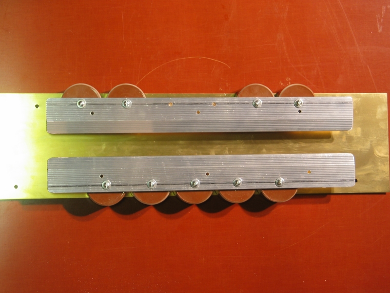
I started by cutting the aluminum extrusion into two equal lengths. Starting at 2&1/8" in from one end, I drilled a hole every 2.5" along the length of each. This allowed me to mount six 2nf doorknob capacitors on each side, in an interweaved pattern (see photos). I chose the 2.5" spacing because the caps I used, TDK 2nf 40kV devices acquired on eBay, are 2.25" across. It is important, btw, to use caps with wide terminals, for lower inductance and better speed; it is also much better to use Strontium Titanate caps than Barium Titanate ones. (Check the mfr’s specifications.)
If more capacitors are available, and if you can find a larger piece of brass for the baseplate, you may want to try scaling the laser up. You should be able to fit 12 capacitors on a 3-foot length of carpet edging, and the resulting laser should have substantial output power and energy. You may want to use a larger spark gap switch, however, to handle the extra current, if one is available. I would suggest, btw, that if you do have more capacitors, you put them in a single row on each side, as close to the channel as is practical. It has been found that they become much less effective as they are placed further and further away. (See the references for information about this and other aspects of nitrogen laser construction and operation.)
This is the schematic diagram of the laser; I have omitted a current-limiting resistor in the —HV line, for simplicity. Note that it is possible to use a charging resistor rather than the charging inductor shown here; Milan Karakas suggests that a HV resistor (of perhaps 30k to 100k ohms) may provide slightly improved performance, but I have not tested this conjecture.
Notes: The spark gap I’m using is an EG&G GP-70 (acquired on eBay); EG&G literature refers to the electrodes of their spark gaps as “Trigger”, “Adjacent”, and “Opposite”, so I’ve labelled them that way in the diagram. I have indicated the cathode of the laser with a circle, and the anode with an arrow.
Here is a photo of the spark gap in place:
(The white wires slanting up and to the right carry the trigger signal.)
You can see a pair of small capacitors on the right side of the GP-70. A spark gap, at least one of this type, needs an initial current of about 10 amps to form a good conduction channel; the little “start cap” pushes at least 10 times that much current, with a very short risetime, so that the gap switches on faster. This technique actually does not seem to be crucial here (it seems to give me only about 5% more energy per pulse), but I have found it very useful in cases where the main cap that I am switching is large (for example, dye laser flashlamp drivers).
(The start cap is slanted because it is not what I had
in place originally. Under ordinary circumstances it
should be more or less vertically oriented, and should
be placed as close to the spark gap as possible, to
minimize associated inductances.)
When you fire a pulsed laser like this one, you generate a sharp electromagnetic pulse. This pulse can damage equipment that is connected to the laser. I always put a choke in the “hot” line from the power supply (sometimes more than one), and I also put one in the ground line. If you are attempting to measure the output of your power supply with a voltage-divider, put a choke in each of the wires going to the meter, as close to the meter as possible. You probably also want a small capacitor, directly across the meter input, for a little extra bypass.
The reason I know that the EMP from one of these can damage equipment is that I have done so.
Here is a photo of the power supply, with its chokes in place:
Here is a not-very-good ASCII diagram with a very rough approximation of the shapes of the pieces, as an overview; it doesn’t show the floor or roof of the channel, nor the charging inductor.
                                      channel
             o + Trig                    |
             |                           V
        +---   ---+---------+--------\       /---------+--------- GND
         | GP-70 |     ----------     o     o     ----------
         |       |    |    5x    |               |    5x    |
         | SPARK |    |   2 nf   |               |   2 nf   |
         |  GAP  |     ----------                 ----------
        +---------+---------+--------------------------+-------- - HV
The spark gap is, as you can see in the photo above, actually taller than the 2 nf caps; I’ve drawn it at the same height here for convenience. If you build your own spark gap, make it at least tall enough to match the height of the electrode it connects to; I’d suggest even taller, as you will want to run the laser at about 20,000 volts if you can.
Notice that I have grounded the positive output of the power supply, and used the negative terminal as the HV output. This avoids problems with arcs going back up the gas lines. (Helium conducts quite easily.)
Here are some views of the pieces of extrusion. (Ignore the holes that are visible in these photos; they were already present when I bought the material.)

There are 6 caps on each side because it has been determined, repeatedly, that voltage-doubler circuit nitrogen lasers perform best when the two capacitor banks are of equal value. (Besides, each electrode really has room for only 6 of the capacitors. Nothing would be gained by removing any of them just to unbalance the circuit.)
I positioned the two rows of doorknobs on the baseplate so that if I drilled the holes in the electrodes on the second groove (see photos, above), the gap between the electrodes, which is the laser channel, would be about 22 mm wide. This proved satisfactory. (An earlier attempt, with the channel ~35 mm wide, was not viable.)
The following photo shows the electrodes approximately in position. (It’s actually a picture of the earlier version with the wider channel spacing, but it will serve to illustrate the general plan.) Several of the capacitors are not in place.
On a hunch, I decided to try polishing the rounded corners
of the electrodes by rubbing them with ultrafine steelwool.
This wins: they emerged bright, shiny, and smooth, and I
highly recommend this method. In fact, I polished all the
edges of the electrodes this way.
I used a piece of coated front-surface mirror as a rear reflector, and a small fused silica window (acquired from the excellent laserwolfer on eBay) as its output coupler.
Eventually I would like to find an output coupler with somewhat higher reflectance. This is because light travels about 60 cm in 2 nsec, which means that the leading edge of an 8 nsec pulse can make two full round-trips inside the cavity. That may not seem like much, but it’s enough to help narrow the beam to some extent, and if I haven’t saturated the gain, it will increase the power significantly. Having a more reflective output coupler becomes increasingly useful as the pulselength increases, though again with the caveat that if you actually succeed in saturating the gain, the output energy won’t improve much even if the beam quality does.
Here are two photos, with the channel upside down because I have just glued the floor on. Again, these are pictures of an earlier version, without the slot down the middle of the preionizer. They do, however, show the three slots that I milled in the floor of the channel, to discourage surface arcs.
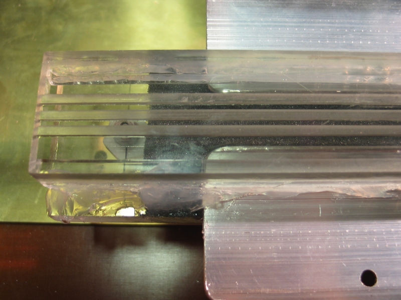
Notice that the floor is a “U” shape, with rectangular bars as sides; the bars are acrylic, and I attached them to the floor with cyanoacrylate adhesive. That’s a relatively inexpensive way to proceed, and it worked, but there may be a better alternative available at your local hardware store. I attached the entire floor assembly to the electrodes with silicone rubber caulk/glue (“RTV”). The roof, however, is attached with epoxy, to hold the electrodes firmly flat and parallel to each other. (I attach them loosely to the capacitors, make sure that they are aligned correctly by propping them up carefully, and then glue the roof on. (Be sure you give the epoxy time to set fully.)
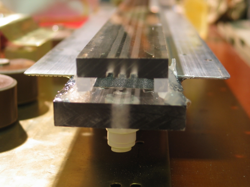
Notice, also, that I have drilled and tapped the roof
and installed plastic fittings to take the polyethylene
tubing that transports the gas mixture into and out of
the laser. I’m not at all sure it makes any difference,
but I am currently putting the gas in at the mirror end
of the channel, and taking it out at the output end.
I should probably point out that it is one hell of a lot easier to
take a slightly nonfunctional surplus commercial laser
and get it running or even
rebuild something that came out of a dumpster
than it is to build one of these from scratch. You learn different
things each way, though, so it’s nice to have the opportunity
to do both.
(11 July, 2005, revised 17 July)
I actually built this laser three times before I got it to work right. I mention that because when you aren’t simply following someone else’s recipe, unexpected things happen and you have to be able to figure them out in order to proceed. One thing that happened to me was that my initial idea for preionization didn’t work the way I wanted it to, so I had to do some testing in order to understand what was going on, and find a viable approach.
Milan Karakas noted in an email message that two patents that he has seen, which cover the use of SiC for preionizing CO2 lasers, had gaps between bars of the stuff rather than a simple flat uninterrupted plate like I was using. This suggested some sort of stripe or fishscale arrangement. I didn’t want to build half a dozen laser channels, so instead I built a little tester out of bits and pieces that I had lying around:
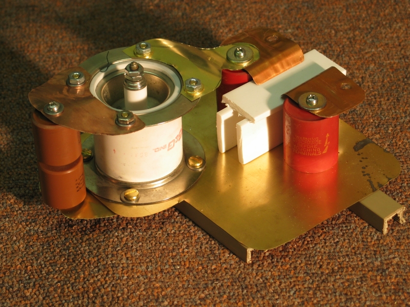
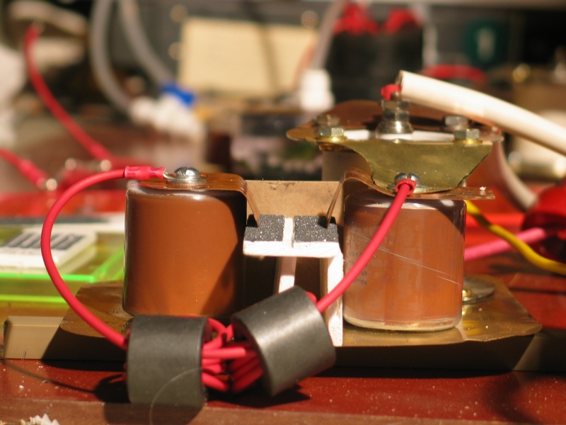
The two brown doorknobs at the left in the first photo are the 200-pf start caps. I swapped out the red Sprague doorknob capacitors that you see in the photos, replacing them with low-inductance SrTiO3 TDK devices. Note the white plastic bars; these are pieces I sawed from a plain flat molding that I bought at the hardware store. I think a 6-foot piece cost me $3.05.
In designing this tester I tried to make its operation reasonably similar to that of the laser. The electrodes are a little over an inch wide, so I used 900-pf capacitors, as they provide roughly the same amount of energy per inch of channel length as I get in “the real thing”. Also, like the laser, the tester uses a doubling circuit.
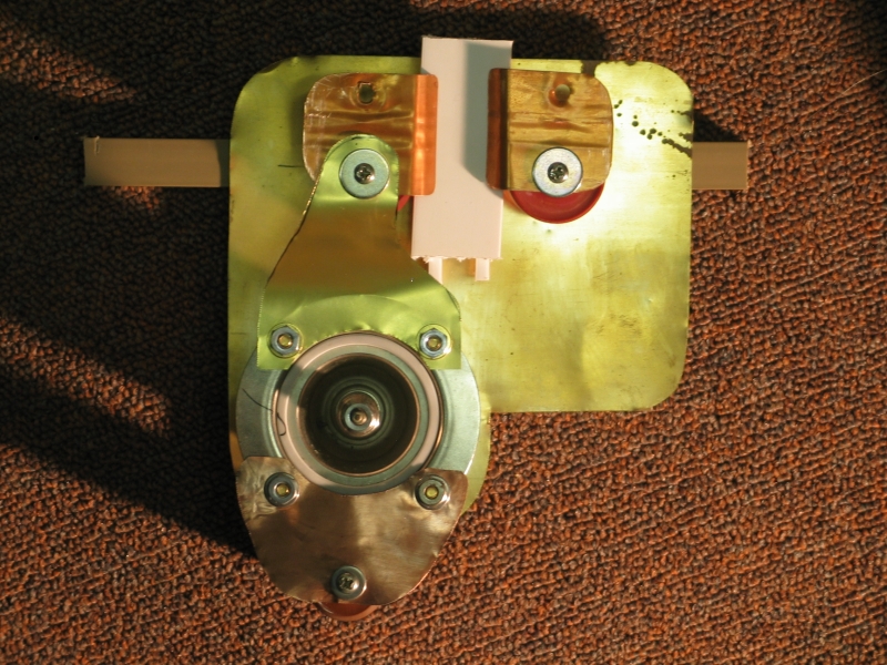
I went through a variety of materials and configurations before finally settling on the structure shown in the photos below, with a 1/8" slot milled down the center of the preionizer plate, and SiC on either side. Here’s the successful test piece, first in room light (you can see the charging inductor in front of the 900-pf doorknobs), and then under test:
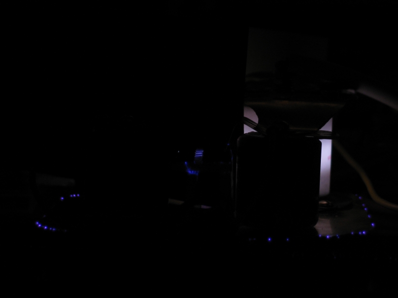
I think the second photo shows about 15 discharges
during a 4-second exposure; the camera was set to ISO 50,
so it wasn’t particularly sensitive, and a single
discharge wasn’t bright enough to photograph. The
pale moonlike glow in the right rear is the spark gap;
you can also see corona coming off various small sharp
points around the edge of the baseplate, at the bottom.
I found, in the process of making the tests, that if I put
the epoxy on fairly thickly, the first application of
Carborundum™ grit sinks into the surface. That may
be okay, but I don’t trust it. If you build one of
these lasers, I suggest that if possible you pour the SiC
on and just leave it in place until the epoxy has
hardened. I was unable to do that, because a little bit of
epoxy managed to work its way into the groove even though
I had stuffed the groove with something in an attempt to
prevent that from happening, and although I removed as
much as I could, some carborundum stuck to what was
left. I had to remove that, as well as I could, before the
epoxy hardened, and I was not quite fully successful.
Nonetheless, the preionizer works, indicating that the
requirements are at least a little bit flexible. (Note,
added in proof: For the next set of preionizers I
made, I took a roll of ordinary sticky tape, cut a slit to
create tape that’s about 6 or 7 mm wide, and ran a
line of that down the preionizer instead of milling a
slot. [I was using glass, so milling wouldn’t have been
very practical.] I also ran a line across each end, so that
there wouldn’t be any grit at the very ends, though I doubt
that it matters much. I brushed epoxy onto the glass,
peeled off the tape, and promptly poured on the SiC powder.
This seemed to work pretty well, but I have not yet tested
the resulting preionizers, so I can’t make any real claims
yet.)
You will need ends for the channel; I built this laser about as simply as I could: I just glued the mirror directly onto the end of the channel with RTV. That, however, wasn’t as simple as it sounds, because it is quite important to align the mirror with the channel.
In order to create that alignment, I started before I attached the floor. With the roof on and the channel upside down on a support, I aligned the beam of a HeNe laser to it, parallel to the electrodes. Then I glued the floor on with RTV, taking care not to disturb either the channel or the HeNe in the process. Finally, when the RTV holding the floor in place had begun to harden and was fairly stable, I glued the mirror on, keeping it held in position so that it reflected the HeNe beam straight back along the channel into the laser. If you are careful about aligning the HeNe with the channel, this is good enough. If not, it is better to build an actual mirror mount, so that you can tweak the alignment later on.
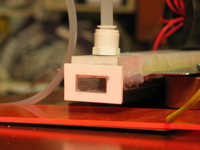
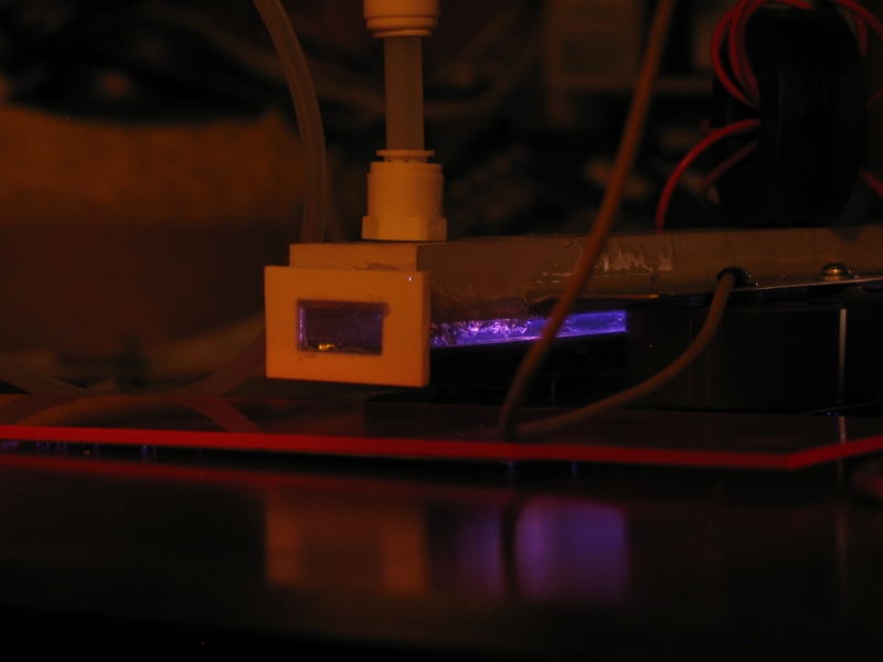
My output window is only ½" x 1", smaller than the hole at the end of the channel, so I cut a small piece of the white plastic molding that I used for the test pieces, milled a rectangular hole into it, and used RTV to fix the window into the hole. Then I used RTV to put the window in its nice new frame on the end of the channel. Here is a photo:
If you want to operate this laser without a vacuum pump, you will need a tank of nitrogen, a tank of helium, a regulator for each tank, some valves, some tubing, a few adapters, and some way to mix the two gases together. I buy my tubing (polyethylene) and adapters (plastic) at the hardware store (see various photos). Somewhat surprisingly, I find that the new plastic adapters work pretty well, even when I am using a vacuum pump. I do, though, take care to cut very clean square ends on the pieces of tubing I use.
There are several ways to mix the gases. I had a surplus passive fluid mixer tube, which I am using, but I also designed an active mixer, using a plastic box and four little 12VDC fans. Two of the fans rotate clockwise and two of them rotate counterclockwise, so I lined them up “ABAB” inside the box. Probably, one or two would have been enough; but I didn’t end up using that mixer, so I don’t know for sure. It seems likely to me that just running the gases together through a coil of polyethylene tube with a few turns would probably mix them well enough; that costs maybe $4, and it involves no difficulty at all.
If you have a vacuum pump and you want to use it, you will want to do a bit of redesign on the channel. Atmospheric pressure is a little less than 15 pounds per square inch; if the roof and floor of your channel are 1.5 inches across and 24 inches long, the total pressure that the channel structure must sustain without deforming will be almost a thousand pounds. This means that the floor and the roof should meet as precisely opposite each other as possible, to avoid flexing the electrodes. I will also suggest some source of nitrogen, because air is a lousy laser. Up to about 0.5% oxygen has been found to help laser action in nitrogen; but beyond that it interferes, and air contains about 20% oxygen. It is difficult to achieve a clean and stable discharge in air, and air has considerably less output than pure nitrogen (much less a nitrogen-helium mixture). On the other hand, if you can get your laser to work with air at low pressure it will certainly work with nitrogen, so air may be a decent test material.
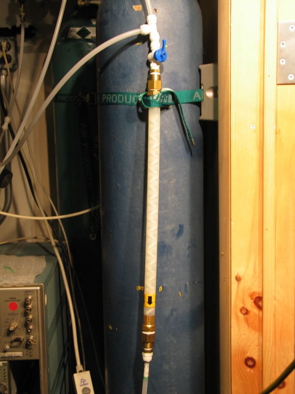
Here is a photo of my current gas mixer. Helium comes in from above, nitrogen enters from the side at the top, and the mixture exits at the bottom. Note the plastic adapters.
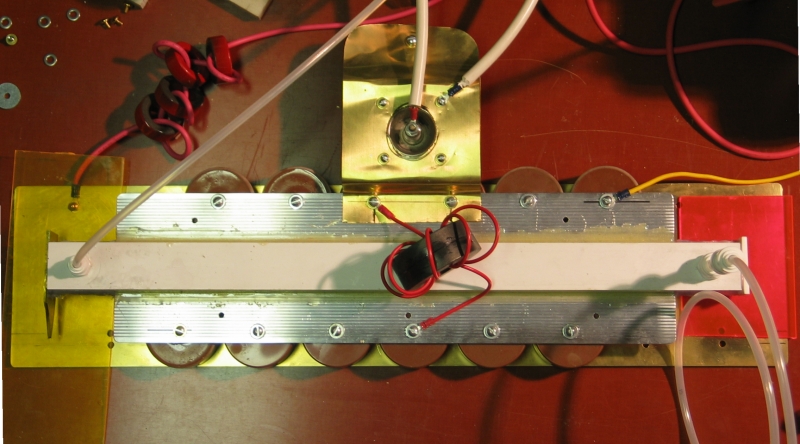
Here is the laser from above. The pieces of plastic under the ends of the channel are there to prevent arcs from forming between the channel and the base. (I had some trouble with this initially, even at reduced voltages.) Eventually I will install something a bit more permanent.
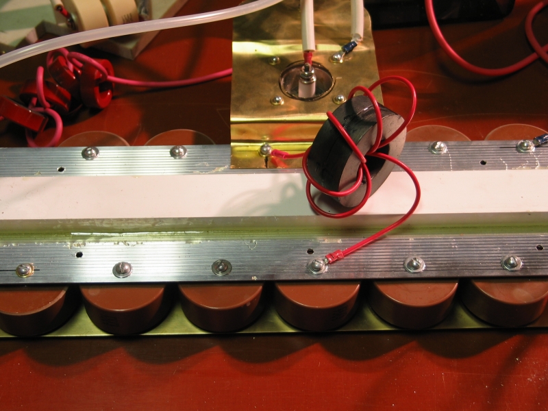
Here are two more views:
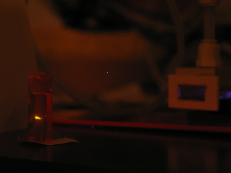
Here is the laser in operation, with its output focused (by a concave mirror that is not visible in the photo) onto a cuvette containing Rhodamine 6G. The charging voltage is about 12,400, and the nitrogen laser is just barely at threshold. (The dye is not lasing, and is used here merely to indicate the presence of output from the nitrogen laser.) I have not optimized the gas mixture.
Here is the laser in operation again, this time at 20 kV, showing the channel as well as it can be seen (not very) through the polycarbonate channel floor:
Here are two views of the dye cuvette, showing it lasing:
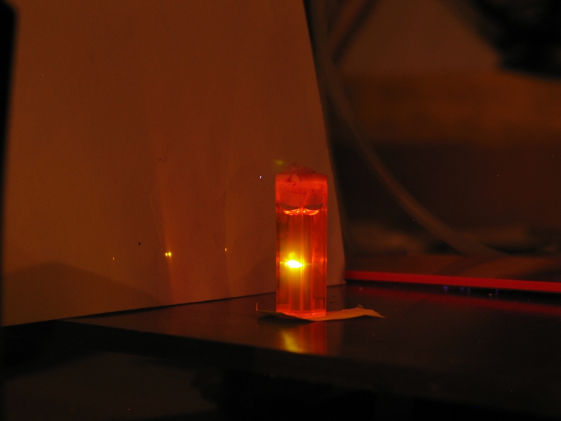
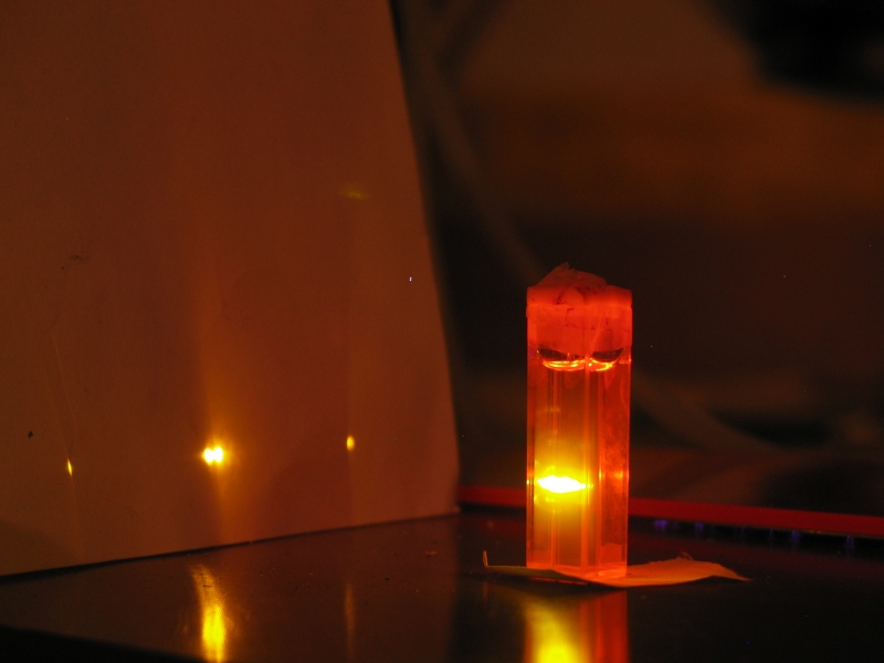
On the left, the laser is running at about 17,000 volts;
the dye is just above threshold. On the right the
charging voltage is 20 kV, the maximum that the power
supply is rated for, and I have partly optimized the gas
mixture. There is a significant difference in
brightness. Note, btw, particularly in the photo on the
right, the cloudy bright region extending out around the
right part of the double dot in the middle of the
pattern on the paper target; I suspect that this is
superfluorescent lasing, though it could be at least
partly just scattering from extraneous particles in the
dye solution. The double dot itself (and the other two
dots, which are apparently from secondary reflections)
are ordinary cavity-based lasing, and result from the
dye using the walls of the cuvette as mirrors.
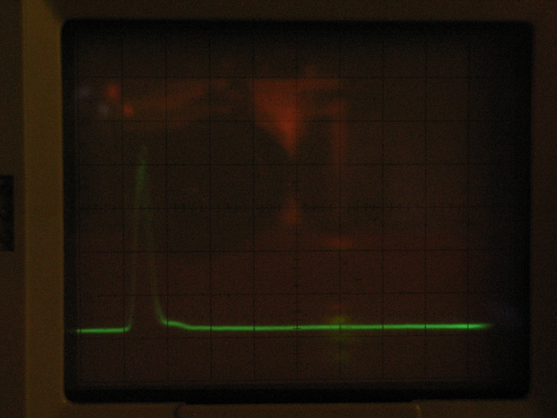
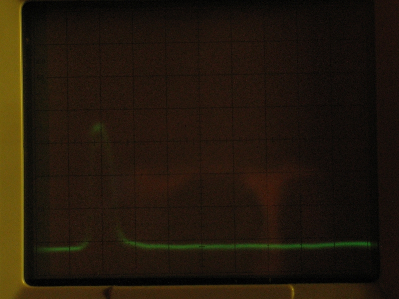
Here are two sets of 24 pulses each (taken during 10-second exposures; I think the second set is actually 25 pulses rather than 24), displayed on a Tektronix 7904 oscilloscope with a 7A29 vertical plugin. The detector (which was biased at 50 to 56 V for these measurements) is a Motorola MRD500, which has <1 nsec risetime at 100V, and should be 1 nsec or less even at 50V, and the plugin is rated to 1 GHz; but the 7904 mainframe is only rated at 500 MHz, so even if these weren’t multiple exposures we might have lost some fine structure (if there was any to lose — there may or may not be). The scope is not as bright as I’d like, so I had the camera set to ISO 200. That’s also why I had to fire the laser so many times; at least it shows the very reasonable shot-to-shot repeatability. The first photo shows the laser as it appears (and is described) above, with only a rear reflector. The second shows what happens when I added an output coupler. (Notice that the peak seems a little wider, or the top of the peak a bit flatter, in the second photo.) At half of the peak value the pulse is probably about 4 or 5 nsec across without a second mirror, and about 7 nsec across with one. (We’re looking at 10 nsec per division here.)
I used a Scientech power/energy meter head to measure the energy output. The head is designed for larger power and energy, so I have to amplify its output in order to measure this type of laser with it. I use one channel of an INA 2141 instrumentation amp chip to do this. With the head plugged into the amplifier (which is set to 100X) and the output of the amp plugged into the scope, I pulse the laser twice a second until the scope trace stops getting any higher. (It fluctuates a little with each pulse, but it is fairly easy to take an average, and the trace seems to stabilize reasonably well within about a minute.) This gives me a relative power level. Fortunately, the head has a calibration resistor built into it, so I can put a known amount of electrical power in and compare the results. That gives me the actual power level, because I’m using the same amplifier to read the same sensor.
In order to get the scope trace to the same place on the screen, I have to put 236 millivolts across the calibration resistor, which is ~40.8 ohms. That represents a little over 1.3 milliwatts. Because I’m pulsing the laser twice a second, however, I have to divide by 2 to get the energy of a single pulse, which is about 680 µjoule. Because the pulsewidth is 5 or 6 nsec, that amounts to perhaps a bit over 100 kW, which is respectable for a small laser. If any of the beam is missing the active surface of the detector (which is possible), then the energy and power are higher than I’ve given them here.
When I put a reflector in front of the laser, the measured
energy goes up to about 740 µjoules per pulse. (I
don’t know the reflectance of the particular mirror
that I used for this test, as it is not specified at 337.1
nm; but I suspect that it is not particularly high.) This
demonstrates the fact that it is not necessarily optimal
to run a nitrogen laser with only one mirror.
This laser utilizes what is probably best termed an
voltage-doubling circuit (though it does not actually
double the voltage), in which two capacitor banks are
charged together, and then one is discharged through a
fast switch that has relatively little resistance. The
circuit formed by the capacitor bank, the switch, and the
associated connections inescapably has some inductance,
so it becomes what radio people used to call a “tank
circuit” — a resonant circuit that will
oscillate for a few cycles if nothing interferes.
The resonant frequency depends largely on C (the
capacitance) and L (the inductance), in a predictable
way that I will pervert slightly: the 10% to 90%
risetime is going to be on the order of 1.5 times the
square root of L times C. In other words, if I fire off
this side of the laser all by itself and measure the
resulting oscillation, I should be able to tell what the
inductance is, because I already know the capacitance
(~10.4 nanofarad). Electrical noise from the trigger
system makes that very difficult, however, and I have
not yet been able to perform the measurement. Moreover,
what I’ve stated here is a gross oversimplification.
For a much better analysis, read the Persephonis et
al. paper from 1993 (see the references).
What I expect is that the risetime is about 35 nsec,
because I think the inductance of the spark gap added to
the inductance of the capacitors and associated physical
structure should be on the order of 40-50 nanohenry. This
corresponds to something like 175 nsec for a full cycle,
which means that the resonant frequency is a bit less
than 6 MHz unless I’ve dropped a decimal place
somewhere.
In normal operation, however, things are somewhat different.
Both capacitor banks get charged, and as the switched bank
“rings down” during its first half-cycle, the
voltage across the laser channel (which is between the two
banks) increases rapidly; if the channel doesn’t
conduct, it can get as large as ~1.9 times the initial
charging voltage. Typically, of course, the channel
does conduct, and that limits the voltage that can
develop across it.
These things are difficult to measure, but in general,
from what I’ve read, I think that the voltage
across the channel rarely manages to exceed 1.2x the
initial charging voltage in ordinary operation. The
advantage of this circuit is that when the channel
begins to conduct, the capacitor bank that drives it is
looking into a negative voltage on the other bank, which
is, in some sense, even better than a dead short to
ground; and the capacitors are discharging not so much
through the switch as directly into the capacitors on
the other side, so the risetime of the discharge in the
channel is short. (The fact that the main store is
divided into two pieces probably also gives you a little
bit of help in this regard, because smaller C has
inherently faster risetime, and the two banks can
presumably be considered separately.)
Nitrogen lasers using this type of circuit tend to have
fairly good efficiency, relatively speaking, and are
only moderately sensitive to the inductance of the
switched side. This is part of why the Scientific
American laser works. (Any talk of “the instant
the switch closes”, however, is simply nonsense:
even if the word “instant” had any meaning
in electronics or physics, which it doesn’t, there
can’t be any such instant because the switch design
has huge inductance and is free-running, so it is terribly
slow. This laser, in contrast, uses a triggered switch,
which has somewhat less inductance and should be
significantly faster. It still doesn’t close in
an “instant”, though.)
When the laser channel begins to conduct, electrons
travel through it, bouncing off the gas molecules and
(we hope) exciting some of them into the upper laser
level. As I mentioned in the first page of this set,
the electrons have to have a certain amount of energy
in order to accomplish this, and that energy can be
related directly to three parameters: the voltage across
the channel, the width of the channel, and the nitrogen
pressure.
My charging voltage is typically 20 kV, but I doubt
that the voltage across the channel ever gets much
higher than about 10 kV. The channel is about 22 mm
wide. If we suppose that optimum operation takes
place at about 100 V/T·cm, it looks like the optimum
partial pressure of nitrogen will be roughtly 45 Torr.
I have no way of measuring the gas mixture, so I just
tune it for best operation. Fortunately, it is not
necessary to be precisely at the optimum: in the papers
I’ve read, the peak appeared to be fairly broad,
and anything within about a factor of 2 should be viable
if you are concerned only with whether the laser is
going to be above threshold. (This matches my experience
with the commercial nitrogen lasers that I have operated.)
Moreover, at least one paper reports that the addition of
helium to the discharge causes a change in this value, and
those experimenters reported their best operation at about
86 V/T·cm with helium constituting about half of the gas mix.
(Rickwood & Serafetinides, “Semiconductor Preionized
Nitrogen Laser”; see the references
if you want more detail.)
Obtaining a smooth and even discharge is crucial to the
operation of any nitrogen laser. (Sparking, if it occurs
after the end of the laser pulse, is not particularly
objectionable, so if a given laser channel makes sparks,
that may or may not mean much about how well it works.)
There are various ways to accomplish this. One is to run
the laser at rather low pressure, where it is easier to
achieve a smooth discharge. That, however, limits the
amount of energy you can get by limiting the number of
nitrogen molecules that are present. Another is to add
helium to the gas, as mentioned above. This seems to
have a stabilizing influence, and seems very promising.
Helium alone, however, is not enough. A third method is
to preionize the gas in the channel, either by firing at
a relatively high repetition rate to take advantage of
lingering ions from the previous pulse, or by other
means. Because nitrogen works better when it is cold,
using a high repetition rate decreases both power and
energy per pulse, not exactly what we are looking for;
because of that, and because I had no easy way to remove
excess heat from the laser, I decided to use a different
method.
To find out how well it could be made to work with
nitrogen, I adapted a method from the Rickwood &
Serafetinides paper mentioned above (and other papers),
and developed a technique involving silicon carbide
powder in an epoxy coating.
The underside of the top wall of the laser channel (a piece
of plastic sheet), has a 1/8-inch wide groove milled
into it. The two strips on either side of the groove are
coated with epoxy, and while the epoxy was still fresh and
wet I sprinkle 100-mesh carborundum [I think that’s a
trademark] grit on it. I allow this to sit until the epoxy
has hardened.
At ordinary voltages, silicon carbide in grit form does not
conduct; but when the electric field becomes high enough it
switches to a highly conductive mode. (In fact, larger
pieces have been used in lightning arrestors for power or
telephone lines.)
The discharge across and through the SiC surface and
the sparks that jump across the 1/8" gap generate lots
of ions and a certain amount of UV light, which preionize
the channel nicely.
Speaking of which, the next question is how long the
electron energy will stay in the viable range, because
this has a strong influence on the length of the laser
pulse and the amount of energy in it. I will only be
able to determine this one by measurement. If the laser
pulse is well under 10 nsec long, then I’m not
sustaining the E/p value well. If, on the other hand,
the laser pulse is more than about 12 nsec long, then
I’m doing extremely well.
Even given a pulse as short as 8 nsec, there is the
optical cavity to consider. Nitrogen lasers are typically
operated in what is best described as superfluorescent
mode, with at most one mirror. (A few people think this
means that nitrogen lasers aren’t really lasers;
those people have failed to do their homework. LASER
stands for Light Amplification by Stimulated Emission
of Radiation, not “Light Amplification
Inside a Fabry-Perot Resonator”. Moreover, I have
recently heard that some idiot is claiming that the
nitrogen laser isn’t coherent at all (not true —
coherence is not binary, it’s a measure, and
essentially any light source has some degree of
coherence) and that because it isn’t coherent, it
isn’t a laser. This is absolute crap. Stimulated
Emission is a coherent process, at the quantum level.
This means that lasers, in general, have greater coherence
length than most nonlaser sources; but an untuned dye laser
may exhibit shorter coherence length than a nitrogen laser,
a diode laser almost certainly exhibits much shorter
coherence length than a HeNe, and the entire argument is
garbage in any case because actual operating lasers that
sit on tables are macroscopic objects, not just a few
atoms, and they are not in the quantum realm. Yes, lasing
itself is defined in the quantum realm; but when
you scale up to human proportions for an actual device,
you are at a different level; things do not exhibit
the same behaviors, and you can’t simply pretend that
it’s all exactly the same when ten-to-the-16th-power
photons are involved as it is when there are only 2.)
Postlude: Theory of Operation
Other Factors
On to a development page in which I revise and expand this design
in an effort to improve its performance
On to the “How-To” page about the revised design
On to the development page for my next nitrogen laser
My email address is a@b.com, where a is my first name (jon, only 3 letters, no “h”), and b is joss.
My phone number is +1 240 604 4495.