(Note, 29 September, 2006: This is a revised page that I have substituted for the original stub.)
This page follows the development of a high-performance nitrogen laser that is intended for DiY construction. By “high performance” I mean that this design is intended to deliver at least half a megawatt. Whether it will actually do so depends on whether it is a viable design, and on how well I implement it. Even if it fails, I should learn enough from it to achieve my (half-megawatt) goal with the next one, and the information will also help me reach the 1-MW goal that is the aim of this project.
I should perhaps point out that a megawatt is easier to achieve with a TEA nitrogen laser than with what Jarrod Kinsey refers to as a “TERP” (Transversely Excited [at] Reduced Pressure); but the energy in a 1-MW pulse from a TEA laser is only about 1 mj, whereas a 1-MW reduced-pressure nitrogen laser of an ordinary sort must put out 6-10 mj in order to reach 1 megawatt peak power, because it produces a much longer pulse.
This laser operates at a voltage of about 35 kV, and delivers up to ~360 kW peak power (at full operating voltage) in a pulse that can be more than 8 nsec long.
The design is not hard-and-fast, nor is it restrictive. It can be modified at need, or upon desire. For example, a DC preionization scheme can be used instead of the semiconductor scheme I show in the design. (See the Rebhan et al. reference for an example; there is a link to the references at the end of this page.)
Readers who have built small nitrogen lasers should note
that this is a more complex dance. Several factors have
to be optimized, and they tend to interact, which means
that optimization requires careful observation and a
certain amount of critical thinking. A designer of
commercial nitrogen lasers once told me that anybody can
build a 100-kW laser; that it takes some expertise to
get to the 250-kW level; that you really have to know
what you’re doing to build a 500-kW device; and
that only an expert can get a full megawatt out of a
(low-partial-pressure) nitrogen laser. In short, if you
have never previously built a nitrogen laser or a
significant high-voltage pulser, this is not the
right place to start.
1. This laser uses high voltages, and capacitors that can store lethal amounts of energy. It puts out an invisible ultraviolet beam that can damage your eyes and skin. It is important to take adequate safety precautions and use appropriate safety equipment with any laser; but it is crucially important with lasers that involve high voltages and/or produce invisible beams!
2. When you fire a laser that stores substantial amounts of energy and discharges that energy in a very short time, you generate a sharp electromagnetic pulse. This pulse radiates out from the laser circuitry, and can damage equipment that is connected to the laser, or even close to it. I always put one or more large inductors “hot” line from the power supply, and I also put one in the ground line. If you are attempting to measure the output of your power supply with a voltage divider, put a smaller choke in each of the wires going to the meter, as close to it as possible. You probably also want to put a small capacitor directly across the meter input, as an additional “snubber”.
(I should note that I have actually damaged equipment with the EMP from a laser of this sort, which is how I know that it can happen.)
As you will see further down, I am probably going to hang a grounded screen in front of the laser, to reduce The amount of EMP going out into the room.
3) Because of its construction this laser also puts out
a sharp acoustical pulse when it is fired, and ear
protection is mandatory. (This is to say nothing of
the incredibly loud noise that occurs if something arcs
over and takes the full energy of the main storage capacitor.)
If you click any of the small photos or images (except for the schematic diagram, which is already full size), you’ll get a bigger one. Most of them are 1024 x 768 px, or 768 x 1024 px if they are in portrait orientation; some of the more recent ones, toward the end of the page, are 1280 pixels across.
In many cases, if you want the full-size original (2272
x 1704 px) you can just change “.10c.” (or
“.c10.”) in the filename to “.22c.”
(or “.c22.”). The exceptions mostly have the
letter “c” immediately following the initial
image number. For example, if there were a file named
“1848c.italianrevolution.10c.jpg”, it would
have been cropped from the original, and thus a .22c
version probably wouldn’t be available. If you
have some desire to see a larger version of a cropped photo,
and I do not specify the value in the accompanying text,
please send me an email message about it. (In case you
were wondering, by the way, I do not have pictures from
any of the 1848 revolutions. Pyrogallol, the first
really usable developer, was not introduced until 1851.)
(20 July, 2005, et seq.)
Like its predecessor, my initial version of this laser used silicon carbide grit in an epoxy coating as a preionizer. I believe that semiconductor preionization in general is adapted from CO2 lasers; the specific method I use, which involves silicon carbide grit embedded in the surface of an epoxy layer on the inner surface of one (or both) of the sidewalls of the laser, appears to be novel. Because the spacing between the sidewalls and the channel can be set essentially arbitrarily, and because silicon carbide grit is cheaply available in many different sizes, this method is quite inexpensive, and it allows some adjustment of the characteristics of the preionizer[s].
Unlike its predecessor, which was a “Voltage Doubler” circuit, this laser uses a Charge-Transfer circuit. The overall efficiency is almost certainly lower than that of the previous design; but because the peaker capacitor is not on charge all the time, it is possible to build it with a liquid dielectric. This allows me to create a design that facilitates some transmission-line behavior, which I hope will result in significantly improved performance. (Please see the first page in this series for the rationale behind this decision. See, also, the link to references and the links to other pages that are at the end of this page. The Cubeddu and Curry reference and the Rebhan et al. reference are specifically about “water-cap” nitrogen lasers.)
I performed initial tests using the second head I constructed for the previous laser. That head has ~25 mm (1 inch) channel spacing, and is about 88 cm (a little less than 36 inches) long. These values are probably suboptimal; to avoid arcs and sparks at the ends of the electrodes, which often interfere with lasing, a discharge with ~70 to 75 cm active length should have electrodes at least 1 meter long. Also, the Rebhan group reports that channel spacing of less than 38 mm decreases performance. Granted, this design is significantly different from theirs; but there are enough similarities that I expect 25 mm to be less than the optimum value. (In contrast, one of the other references, a much smaller laser, found optimum channel spacing of just under 10 mm. This is, clearly, a design-dependent parameter.)
[Note, added on 06 March, 2007]
I was unable to get that head to lase with this driver, for reasons that are not entirely clear. I observed sparking at the lowest pressures I was able to obtain, which appears to indicate insufficient preionization, something I had been concerned about partly because the orientation of the head was effectively inverted, with the preionizer close to the driver cap, rather than on the opposite side. (I shifted to wire-driven DC preionization when I built a new head. I also opted for much longer electrodes, which should help, per the above information.)
[Note, added on 22 March, 2007]
I begin to think that subthreshold operation, especially when there is reason to expect the laser to be working normally, can sometimes be indication of contaminated water or some other problem with the watercap. Check to make sure that there are no significant bubbles inside the cap, and replace the water with fresh HP [High-Purity] water. (Distilled water is not good enough for this service.) If that doesn’t ameliorate the problem, try different gas pressures, different preionization, and different gas mixtures — the amount of helium in the mix may be important.
(14 October, 2005, ff)
The authors of at least one of the references, without citing a source, state that nitrogen lasers are known to work better when they are pumped far above threshold. This claim appears to be borne out by results reported in other papers; fast circuits that deposit at least 40 J/l into the discharge are the rule, and some devices deposit more than twice that much. I do not recall having seen more than perhaps one paper in which the authors were able to saturate the gain of the laser medium, and that is a significant fact — it suggests either that we could build longer channels or that we could pump the gas a lot harder (probably both), and get significantly more output from our lasers.
Low-pressure lasers with channels on the order of 3 cm spacing seem, in general, to initiate when the voltage across the channel is in the range of 15-25 kV; for the purposes of guesstimating the performance of this design, I will arbitrarily decide that this laser should start conducting at about 20 kV. At that voltage, the peaker capacitor, which should be just under 30 nf, stores almost 6 joules; the active part of the first test channel is 2.5 cm wide, about 0.4 cm high (the electrodes are just over 3 mm [1/8"] wide, but I am allowing for some spread in the discharge), and roughly 65 cm long (I am allowing for excitation a little beyond the edges of the peaker, which itself is between 55 and 60 cm wide), for a total excited volume of 0.055 l. If I [arbitrarily] decide that half of the energy from the peaker gets into the channel during the important period (initial pumping followed by lasing), this gives me about 54.5 J/l if the main storage cap provides nothing directly to the discharge. The Rebhan article, however, makes it quite clear that the main store does contribute significant amounts of energy: when they decreased their main store below 120 nf, they found that the output from their laser was reduced. My main store is only 89 nf, somewhat small, but it should certainly help, and the calculated energy density is reasonable. For comparison, the Rebhan laser developed 1.5 MW peak power in a pulse that was about 12 nsec long, FWHM. This laser is not going to be in that class; but I do hope to see at least 500 kW from it once I get it optimized, and there is a small chance that it could reach a full MW.
To those who have built small or midsize nitrogen lasers, 120 nf probably seems like a ridiculously huge value. (For comparison, I think the total capacitance of the Scientific American nitrogen laser is about 12 nf.) It is worth noting that for a given circuit inductance, the risetime and pulsewidth should track the square root of the capacitance, so 120 nf should only be about 3x slower than 12 nf. At a high enough voltage, this may be an acceptable tradeoff. (The Scientific American laser runs at about 12 kV; the Rebhan laser runs at 30-35 kV.)
Moreover, by the time the peaker has been charged up enough to initiate current flow in the laser channel, a large amount of current is already flowing out of the main store. Once the channel initiates, this current adds to the current supplied by the peaker, supplementing it. An argument could be made, in fact, for putting the main store and the peaker on opposite sides of the laser channel, to see whether a slight increase in output would result. (I do not know of any group that has tested this conjecture.)
Something that people mostly don’t think about is the fact that it does take some time to achieve a population inversion. That is, a nitrogen laser does not even begin to lase until perhaps 10 nsec after the laser channel begins to conduct and significant amounts of current start to flow through it. It is possible that this is one reason why low-pressure nitrogen lasers are relatively forgiving: even though they don’t perform particularly well if the driving circuitry is on the slow side (relatively speaking), they do usually lase. A really high-performance nitrogen laser, however, simply isn’t possible with suboptimal circuitry: you must deposit a large amount of energy into the gas in a short time, and you must do it with electrons that have enough energy to pump the nitrogen molecules to their upper laser level.
For pulse-charging applications where the capacitor will never be on charge for more than about 500 nsec, water is a superb dielectric. It has dielectric constant of 79 or 80 (different researchers give slightly varying results), and for times of 500 nsec or less its dielectric strength is at least 1 MV/cm, significantly in excess of what is required — if we assume that channel breakdown starts at 20 kV, the peaker capacitor of this laser will sustain a maximum of only about 67 kV/cm. (See the reference at the end of this page for more information.) Moreover, because it is a liquid, it is self-healing when punctured, and it is extremely easy to replace when its performance begins to decay.
The downsides are the fact that it is a liquid, and will tend to leak; and the fact that it must be extremely pure and clean for this application. Distilled water is not good enough; it conducts electricity well enough to steal a significant amount of energy from the discharge. It must either be distilled a second time, or run through a deionizer of some sort. I was lucky: I found a deionizing cartridge and, later, 5 pounds of nuclear grade deionizing resin on eBay, and those are what I intend to use; but it is easy enough to build a small still, or even two small stills. (If you do decide to distill the water, I would suggest running a few gallons through the still and tossing it out, as it should remove a certain amount of contamination from the condenser and receiver. Once you have gotten the still clean, you can make pure water when you need it. it is probably best to prepare this water fresh when you need it, as it will tend to degrade in storage unless you have appropriate [and extremely clean] storage containers.)
Either as an alternative, or for those who do not have easy access to deionizers, there is some chance that a good faucet filter could serve well enough if you start with distilled water and pass it though the filter (which should be the kind that removes organics, metals, and particles) several times. Here is a commercial filter that I have adapted:
Notice that I have used plastic quick-connect fittings intended for garden hoses. This avoids metal. (There is one metal adapter, on the inlet to the filter; I have coated the inside wall of that adapter with RTV even though it probably isn’t necessary — I am actually going to use this as a recirculating prefilter, to keep the water reasonably clean before it goes into the intermediate and final filters.)
I filed the bottom flat before epoxying the fitting to it. This provides a flat surface to mate with the surface of the fitting (which I also filed, to flatten it), and also provides fresh, clean, and slightly roughened plastic for the epoxy to adhere to. Even so, I do not trust the strength of the joint, and I will do my best to avoid stressing it.
Notice, by the way, that I have epoxied the inlet in the “filter on” position, to avoid accidental spills.
I notice that when I use this filter, there is a slow drip from the outlet I’m not using. I may cap that outlet, but in the meanwhile the drip gives me a visual indication that water is actually going through the filter.
My use of a water-capacitor is (as I mention above) partly an attempt to encourage transmission-line behavior.
In order to get significant transmission-line behavior from a capacitor, you have to match its impedance to that of the load, and the capacitor has to be constructed correctly. This laser uses commercial stainless steel trays (acquired from a restaurant supply vendor) with water between them as the dielectric. If you cannot locate a store that supplies restaurants, you may be able to find a pair of reasonably-well-matched stainless steel trays at a thrift store or on eBay. Alternatively, you can use aluminum trays, so long as the bottoms are smooth and flat. Avoid trays that are dented or scratched, and be sure to choose trays that have rounded edges on their bottoms — sharp corners produce abrupt changes in the electric field, and will cause breakdowns in the water.
This is also true of the ends of the electrodes in the head, by the way; they should be rounded off carefully and polished smooth, to minimize arcs and sparks. (There are mathematically-defined optimized profiles, but they are not easy to create by hand.)
The impedance of a transmission line of this sort is, at least approximately, 377 divided by the square root of the dielectric constant, times the spacing between the plates divided by the width of the line. (This eliminates the units, provided that the spacing and width start out in the same system.) The square root of 79 is roughly 8.9; the bases of my trays are about 18.14" wide; and 3 mm is about 0.118", so the impedance of my peaker will probably be about 0.275 ohms. That’s decent; the effective impedance of the laser channel should probably be between 0.1 and 0.4 ohms at the peak of the discharge cycle.
One hindrance to performance is the fact that the
spacing changes tremendously at the edges of the trays,
going from 3 mm to 60. This changes the impedance, and
thus interferes with transmission-line operation. I am
currently thinking about alternative designs that would
minimize or eliminate this problem; one of them involves
dual lines, and is similar to some TEA nitrogen laser
designs. (If I build such a device I will devote a
separate page to it, and I will provide a link.)
Here is the schematic diagram of the laser; I have omitted a current-limiting resistor in the +HV line, for simplicity. The large capacitor at the left is the main store, which is a Maxwell pulse-discharge capacitor rated 89 nf. Other capacitors may be substituted, but they should be at least 80 nf, should have very low effective series inductance (“ESL”), not more than 15 or 20 nh, and should be rated for voltages significantly higher than any you expect to use. (Operating a capacitor, especially a pulse discharge capacitor, at or near its maximum rated voltage results in seriously shortened service lifetime.)
I have shown the main storage capacitor [on the left) and a peaker capacitor [on the right) on the same side of the laser channel in this diagram. That is, in fact, the geometry I intend to use, at least initially; but the schematic is not intended to represent the physical layout of the circuit.
The spark gap I will be using is an EG&G GP-15B, acquired on eBay. This gap is rated for 25 to 36 kV in open air. EG&G literature refers to the electrodes of their spark gaps as “Trigger”, “Adjacent”, and “Opposite”, and I have labelled them that way in the diagram.
You can see a small capacitor at the side of the switch, labelled “Start Cap”. A spark gap, at least one of this type, needs an initial current of about 10 Amperes to form a good conduction channel, which is important for fast switching; this small capacitor (I usually use something in the range of 100 to 450 pf) pushes at least that much current, with a very short risetime. In principle, this should provide increased output energy and power. In practice the effect may be small, particularly with charge-transfer circuits, but it is a good idea to include this capacitor in any case.
I have indicated the cathode of the laser with an
arrowhead, and the anode with a circle. The capacitor
that is close to the laser channel and preionizer is the
peaker. I’ve shown only one preionizer in this
diagram, and that is what I will be using, at least in
the initial tests.
(this section was started on 29 September, 2006)
Here are some of the things you will need if you want to build this laser:
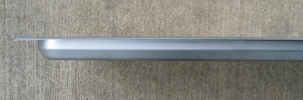
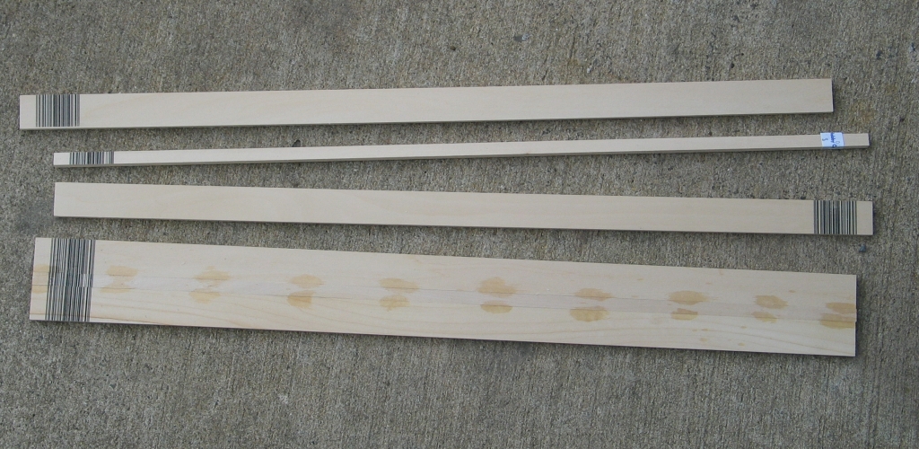
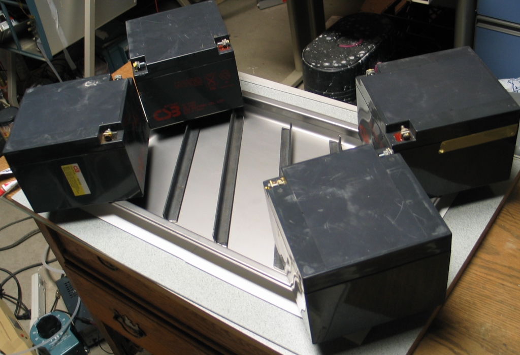
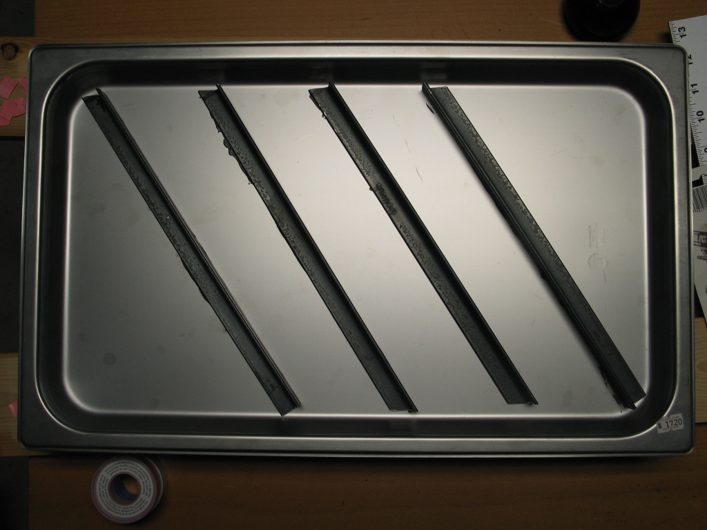
The first image shows most of the parts of the head, except for the ends and end windows. The middle pair are two views of one of the stainless steel trays that are the plates of the water-capacitor. The third is the wooden pieces of a sidewall for the water-cap, one set as bought and one set assembled but not yet cut to length or waterproofed. With the trays I chose, and wood parts that are 2 feet long, three such walls are required. (One gets cut into two pieces.) Note (photo on right) that I have tacked three pieces of wood together with CA (cyanoacrylate adhesive) to make the basis for a wall. The tacked face becomes the exterior, and I paint diluted epoxy on the opposite face to waterproof it. I was obliged to make each wall from three pieces of wood because I needed the walls to be a little over 60 mm tall in order to position the bottoms of the trays 3 mm apart; fortunately, 2X 1" plus 1X 3/8" is just over 60 mm.
The wood in the photo above is only 1/4" (6.25 mm) thick, and was what I could find at the time. I have since acquired wood that is 3/8" (~9.5 mm) thick, and have built the walls from it. The following photo shows one of the water-filter assemblies and the four walls, epoxy-coated faces toward the camera. I must apologize for the fact that it is fuzzy: it was a relatively long handheld exposure.
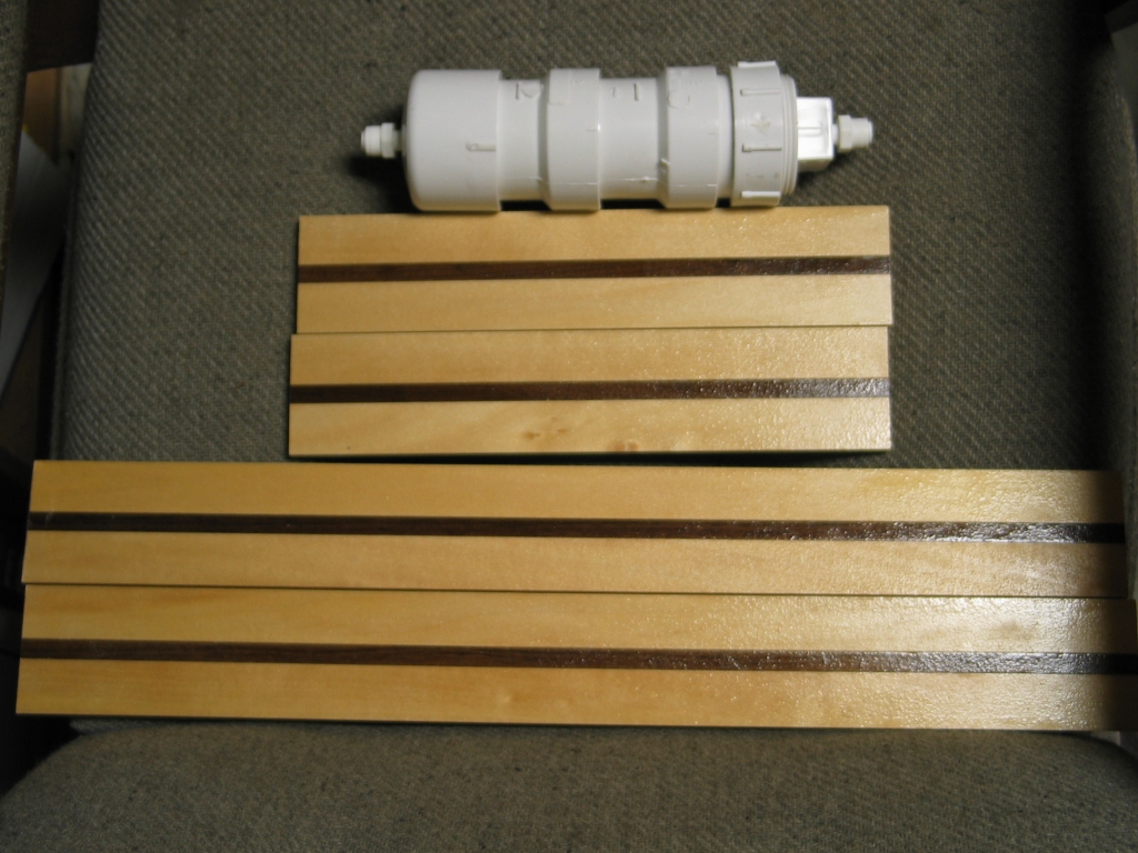
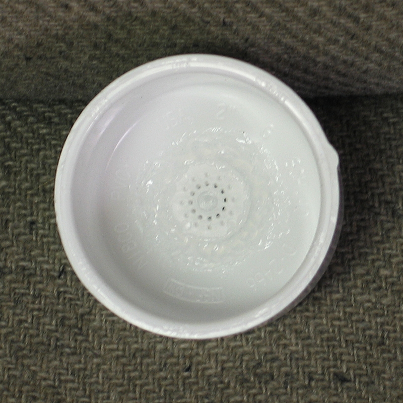
The top of the filter is at the right; water exits to the left. The body of the filter is built from PVC pipe fittings; I have drilled and tapped holes in the top and bottom for plastic quick-connect fittings, as you can see. To keep the deionizing resin from falling out, I have glued the perforated disk from a faucet aerator into the bottom cap with aquarium-grade silicone rubber caulk:
I built two of these filters, because I have two kinds of deionizing resin. I do not yet know whether I will actually need both or just one; but I may just use both in any case, as it can’t hurt and may extend the life of the resin.
(Note, added 06 March, 2007)
When I rebuilt the water filtration system (as I describe
below), I changed these filters out and built a new one
from a length of PVC pipe and some fittings. It is much
longer than the small filter shown here. The screen shown
in the photo above was not adequate, and I used one from
a different type of faucet aerator, with smaller openings,
in the new filter. It appears to work quite well.
(Note, added November 19, 2006)
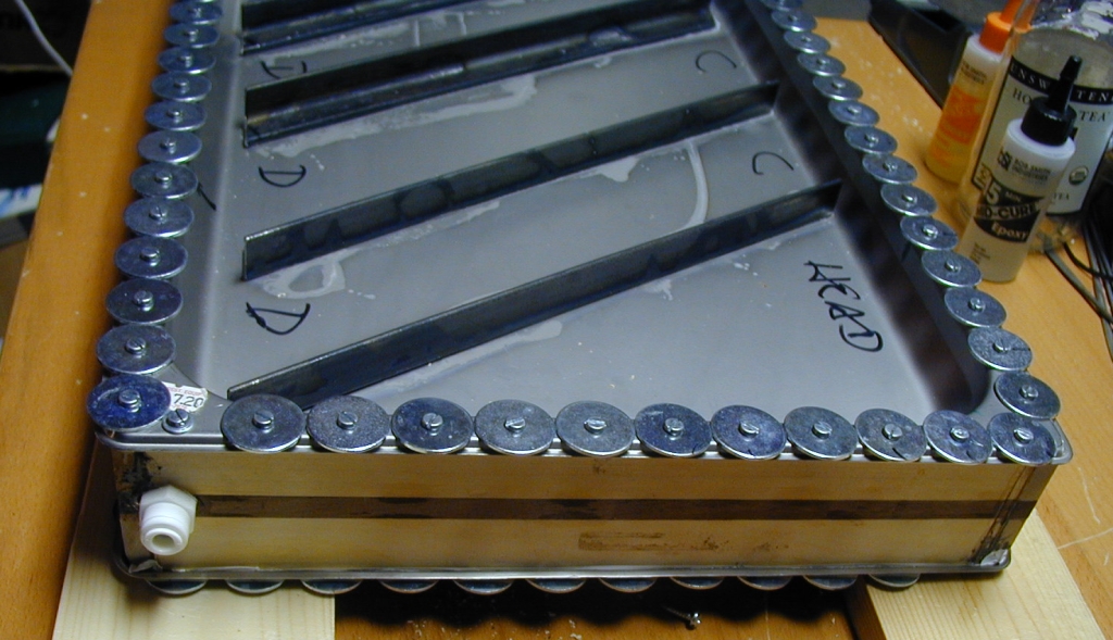
The plates of the capacitor need to be clean and flat; as purchased, the trays were significantly bowed, and I had to flatten them. My initial thought was to press them down on a glass surface (on a piece of paper to prevent scratches) and epoxy stiff aluminum extrustions into them. I figured that should hold them reasonably well. (I am not looking for perfection, just something that will actually work.)
As it happened, I had to put an additional piece of extremely thin cardboard under the middle of the tray, and I had to use multi-kilogram weights at the corners (lead-acid batteries of various sizes are convenient for this purpose, as you can see from the first photo); that combination flattened the bottom well enough. I actually used pieces of angle iron as stiffeners, rather than aluminum extrusion.
Here are: a view of one of the trays in the flattening jig, with the angle iron pieces in place but not yet glued; a top view of one of the flattened trays; and a view of one end of the preassembled capacitor (I have not yet drilled the holes for the screws that will hold the trays to the walls) —
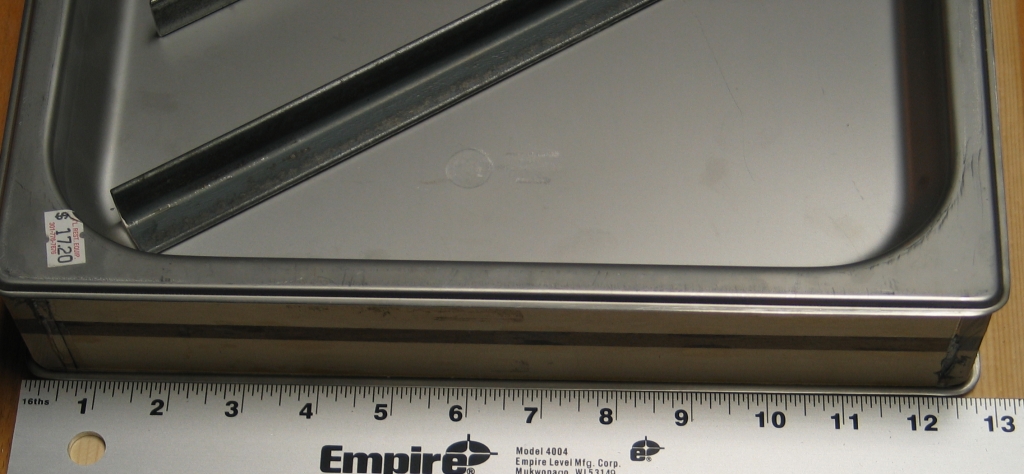
My one lingering concern is the fact that the facing surfaces should be extremely smooth, to keep the electrical field as uniform as possible. Unfortunately, as you can see, these trays have a satin finish. I am considering ways to polish the bottoms, but I will probably just assemble the capacitor with the trays as they are, to find out whether polishing is actually necessary with a spacing as large as 3 mm. (I have read only one article on liquid dielectrics; the authors of that article used spacings of less than 1 mm in their tests, and merely machined their electrodes, which were small, to hemispherical shape; they did not find that any polishing was necessary. I am hoping that this means the existing finish on the trays will be good enough.) In any case, because the structure is simply screwed together, I can fairly easily take it apart for cleaning or other servicing.
With the screws 1" apart, it takes 124 of them to hold both trays on. The screws on one of the long sides will also hold brass shim pieces that connect the peaker cap to the main store and spark gap switch; on the other long side, brass shim pieces will connect the peaker to the laser head. This will make it easy to change out the head, if and when I build a longer one (which I currently intend to do after initial testing gives me a sense of how well the design works).
(03 [text, amended later] and 16 [photos] December, 2006)
My camera is in the shop for repairs, so I have borrowed an older camera for the moment. Here are views of the completed capacitor and the water ports:
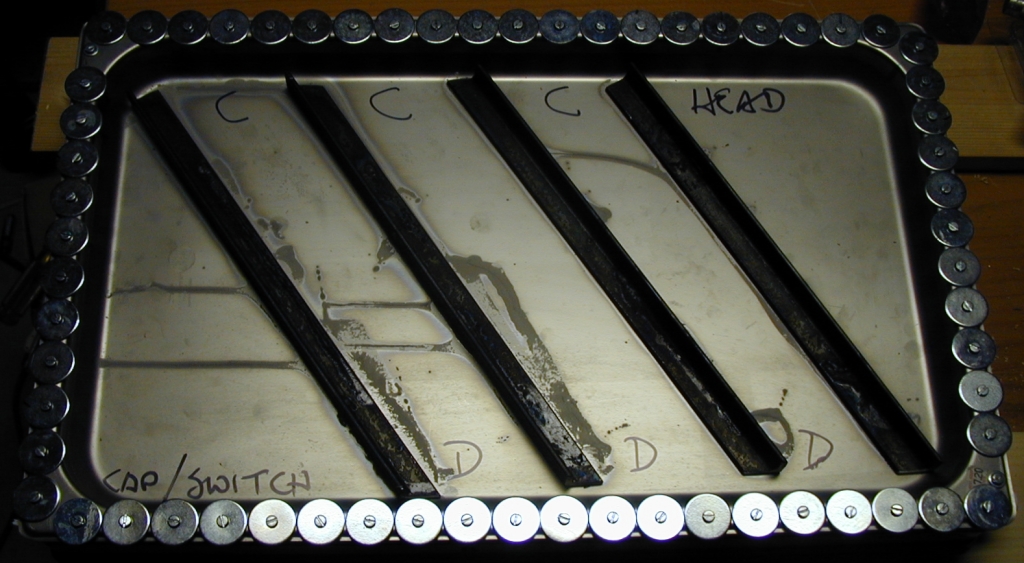
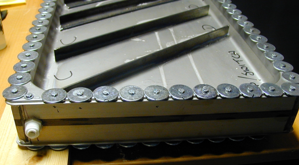
I have not yet had a chance to leak-test it, but you can probably see some stains on the steel, next to the angle iron pieces. These are cyanoacrylate adhesive. Yesterday afternoon I blocked one of the water ports and blew into the other, to get an initial sense of how leaky it would be, and the resulting outward bowing was enough to break some of the epoxy bonds. This is a bit unsettling. My hope is that very little strength will actually be required in operation, but if it turns out that CA is not enough to keep the irons from falling off, I can probably put them back on with more epoxy.
I originally used #6 x 1/2" machine screws, and I was not sure that the wood was holding a few of them well enough, so I swapped the questionable ones out and used #6 x 3/4" at those positions. Because I will probably be using washers under all of the heads to ensure good contact, I will probably change to #6 x 5/8" screws in general, to avoid further problems.
[Note, December 17: I did, indeed, switch to 5/8" screws for most of the locations, and I even rebuilt the threads on a few of the holes with epoxy. Next time I will use a smaller pilot drill or harder wood.]
I put aquarium-grade silicone rubber (“RTV”) caulk on the inner top edges of the walls, and then laid strips of teflon pipe-tape over the tops of the walls before I screwed the trays down. I suspect that this is not quite enough of a gasket, and I think I will add some RTV on top of the teflon tape. When that has had a chance to set I will try to do initial leak-testing, give it a good rinse, and maybe get a sense of the resistance of the cap with distilled water inside it.
(16/17 December, 2006)
I have, per the previous paragraph, added another layer of RTV between the teflon tape and the tray, on both sides. I also added the large washers that you can see in the photos; these spread out the force, and on the long sides they will also provide better electrical contact.
The second layer of RTV should be set by some time tomorrow, and I hope to begin testing then. The first order of business will be to rinse out the cap and then try to measure its resistance when it is full of distilled water.
(17 December, 2006)
Oddly enough, my little filter leaks more than the capacitor. Fortunately, I built two of the filters, and also fortunately, I should be able to de-leak the one I’m currently using.
Be that as it may, I begin to think that a single pass through the filter may not be quite enough, so I am probably going to run both filters in tandem. I am using the fancy resin I got on eBay recently in the first filter, and I will probably use the same resin in the second one. If two passes is not enough, I can always build a recirculator and let the water go through multiple times before I use it to fill the capacitor. (If you do this, and I would seriously recommend it if you are using a sink filter like the one I show above, you should use a pump with no metal parts exposed to the liquid. Pumps that are intended for dye lasers are good for this purpose, as all internal parts are usually made of teflon.)
I have both filters set up, and they both leaked, so I ran a bead of RTV around the relevant seam on each. This will take a while to cure, but I should be able to put more water through them in the morning.
I did a Web search on measuring the resistivity of high-purity water, and discovered that it is generally done with low-frequency AC around 100 Hz; also that it has to be done with rather low voltages, generally less than 1.2 Volts. I will probably set up something that lets me do a measurement using 60 Hz, as that is readily available, but in the meanwhile I think I will probably run a gallon of water through the filters several times, and then filter it one last time on its way into the capacitor. That should be close enough for folk music.
My next task is to complete the setup of the laser, so I can perform HV testing on it. That involves attaching the head to the peaker capacitor, and it also involves attaching the main storage cap and the spark gap switch. Many holes must be made in various pieces of brass shim stock, and also in the electrodes of the laser head. I also have to figure out how to make a stand for the main storage cap, but that should be fairly straightforward.
(2007 January 29, picture amended later)
Here is the laser on the bench:
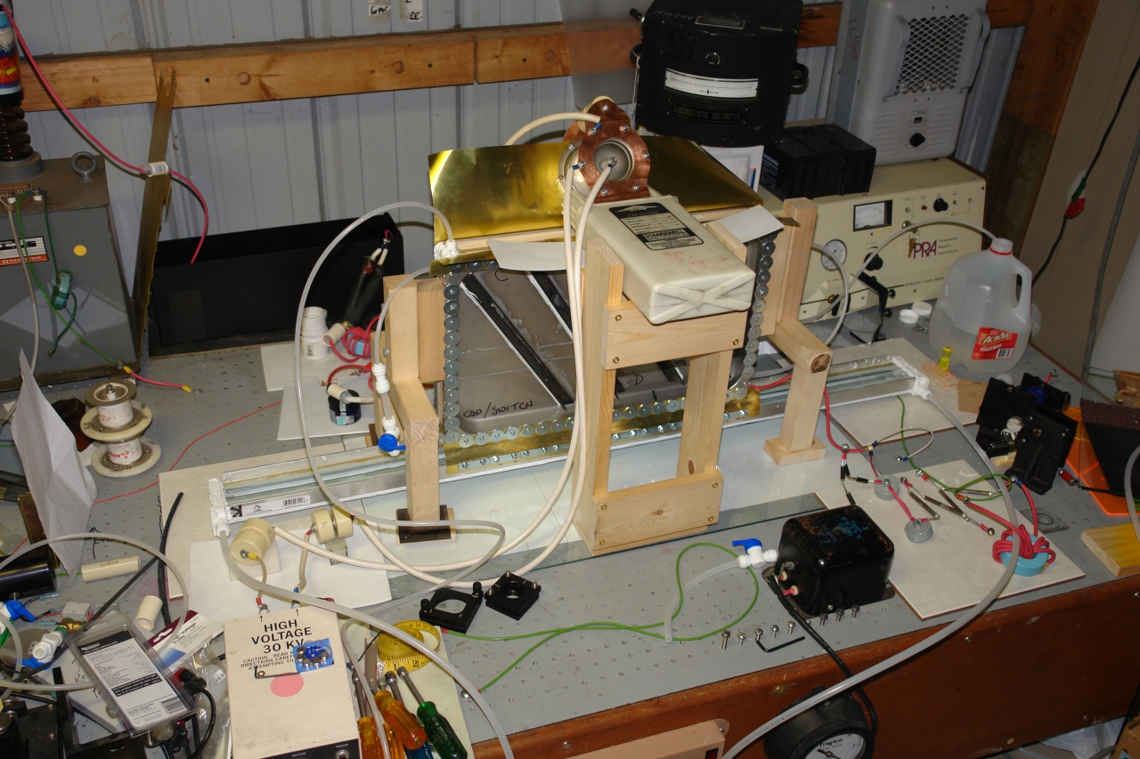
As you can see, the stand for the main storage cap is made of wood, that being readily available and easily worked. Ditto the stands for the peaker capacitor, which are made of commercial legs intended for Parsons tables.
(2007 March 06)
I was unable to get the old head to lase, which worried me a bit. I rebuilt the water-purification system so that it has three filtration steps, the first of which recycles water through the commercial filter I show above; I am also bubbling argon through the water in the recycling tank, to exclude CO2 from the air.
Here is a photo of the revised filtration system; I am using a MicroPump™ on the primary filter, and gravity to move the pre-purified water through the secondary (horizontal cylinder below the table) and tertiary (horizontal cylinder on the table) filters. When I have a bit more time, I will re-orient the secondary and tertiary filters so that they are vertical.
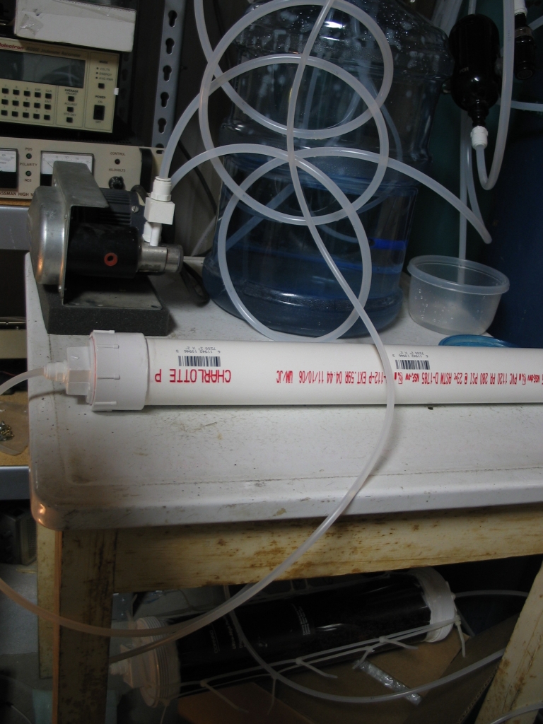
(Note, added on 24 March, 2007: Did that. The filters are now hanging at the sides of the table.)
Improving the water quality did not change the behavior of the laser as far as I could tell, so I decided to build a new head, which you can see in the photo of the laser on the bend, above. This head has glass walls, and uses “L”-shaped aluminum extrusions as electrodes. It also incorporates DC preionization, from an 8-mil (~200 μm) nichrome wire that is driven by a power supply I made from an old oil-burner ignition transformer, through a 50 million ohm high-voltage resistor. This limits the current to perhaps 20 microamps, which should be sufficient. (The positive terminal of the supply goes through the resistor and a choke to the wire; the negative terminal goes to the bench, which is ground. The cathode of the laser is also grounded to the bench. The version that you see in the photo used 400 million ohms, which didn’t seem to provide enough current; but I may revisit this issue later on.)
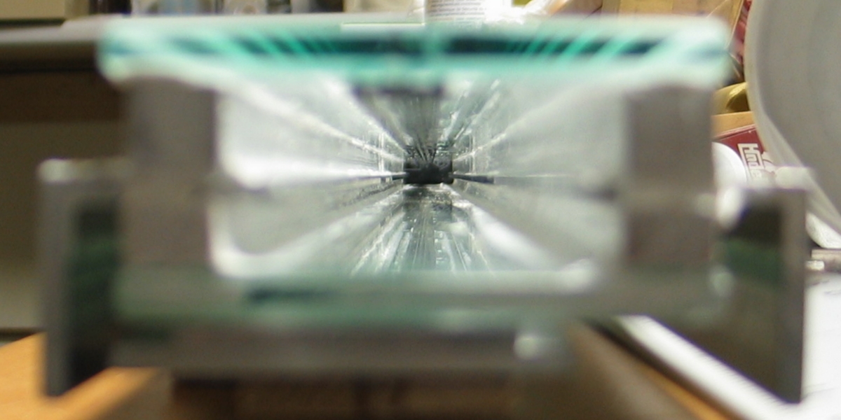
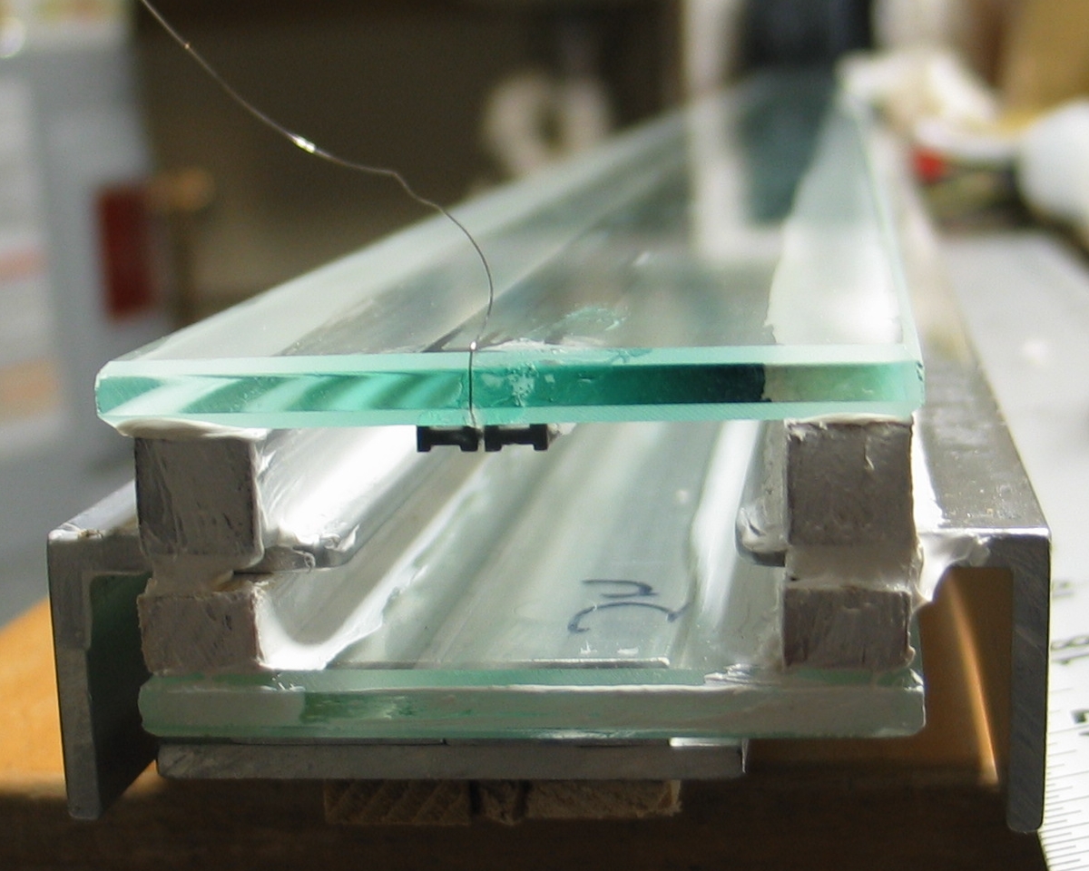
Here are two views of the partially-completed head. In both of them the head is upside down, with the preionizer on the top; in actual operation it will be on the bottom, and the peaker cap will be above the head. The first photo is a view down the channel, and the second shows the end of the preionizer wire.
I made the end caps for the head from basswood, which is too porous. At some point I may make new end caps, either from plastic of some sort or from basswood that I have sealed by painting diluted epoxy on it. (Epoxy can be diluted with isopropyl alcohol, but you want to use 99% purity if you can obtain it; 91% will also work, but the water in it may have some effect on the strength of the cured epoxy. If you do this, remember to coat all surfaces of the wood, and not to stint. You want the wood to be thoroughly sealed.) I used fused silica microscope slides as end windows, but water-white glass microscope slides are probably almost as good. True, they absorb a bit more at 337 nm; but they also reflect significantly less, and if you are not going to align the windows with the beam the increased loss caused by reflection from the silica may balance the increased absorption loss of glass slides.
After I cleared up the obvious vacuum leaks and applied extra RTV to the end caps, I still found that I couldn’t get a good enough vacuum. When I turned on the vacuum pump the pressure went down to just under 100 Torr, and then stalled. I tested the pump and the gauge without the laser head, and that combination went very swiftly down to the lowest vacuum that the gauge can display, even with the hose connected to the final needle valve on the gas supply, so it became clear that the problem was actually in the head and not elsewhere in the system.
Because I did not hear any hissing, I suspected one of two things:
A) Several fairly small leaks, none of them loud enough individually to be audible, but adding up together to a significant source of air.
B) Some sort of distributed leakage through one or more of the wooden pieces. (I put extra RTV on the two exposed spacers, in the hope that doing so might help if this turned out to be the main issue.)
C) Both of the above, and/or something else that I hadn’t thought of or discovered yet.
[The following was written before I resolved the issue.] Unfortunately, I can’t imagine how either A or B could have an effect as large as the one I’m seeing. The wooden spacers are already coated with RTV, and I already did the bubble check twice, the second time actually dipping the ends of the head in water. That check revealed only a few extremely tiny leaks. I guess we’ll just have to see how the next check goes; the air has to be getting in there somehow!
(A bit later)
As usual, it was C. I found only two leaks, but one of them was substantial, and I have no idea why I never heard any hissing from it. I have covered these places with RTV, and when I pulled a very delicate vacuum on the head it appeared to hold quite nicely. I will check again when the RTV has had a decent chance to cure, and I will be very surprised if I don’t get to at least 27.5" of vacuum this time.
If I can get at least 28" I will feel reasonable about checking the preionization, which gave me some trouble during initial tests — arcs formed at one end, and there were only occasional indications of corona elswhere in the head. It is possible that lower pressures will cause this to work better; if not, I will probably have to remove the cap at that end, and cover an inch or so of the wire to stop the excessive conduction. I may try the laser first, though, to see how bad the problem actually is.
(Some time later)
When I tested, the following morning, the gauge went
smoothly down to 29 inches. I was pleased and extremely
relieved.
(10 March, 2007)
As of last night, this device is a laser. I am now beginning to learn to understand it. There is still a water leak at the inlet port of the peaker cap, and I have taken the laser out of service until I can resolve that. Once things are cleanly operable I will begin to characterize and optimize the device, after which I will put up a more thorough “How-To” page about it. In the meanwhile, I am using an aquarium pump to push air through the peaker, in order to dry it out so that I can work on the leak.
(22 March, 2007)
At this point I still have leaks, but they are at the opposite end of the watercap, and they are somewhat slower than the original leak at the inlet; I can now operate the laser. It is far from optimized, but it clearly puts out very reasonable power:
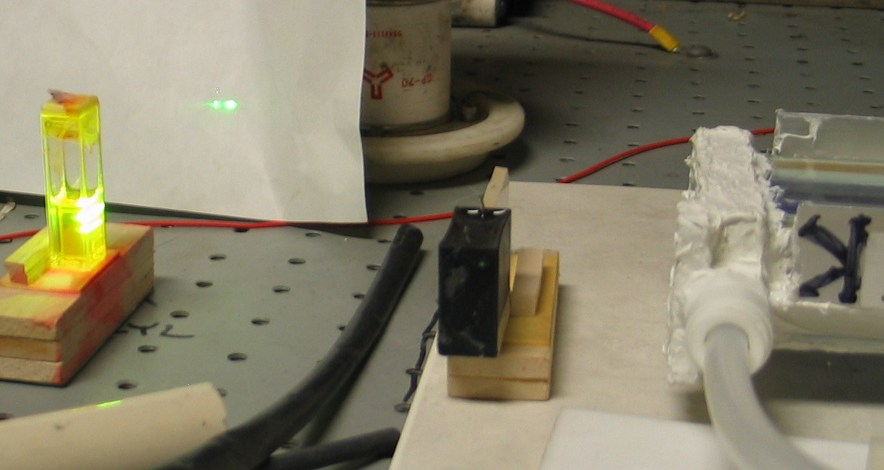
There is a mirror at the opposite end of the head, but it is not aligned; I think it is responsible for the lower stripe of brightness that you can see across the front of the cuvette. The separation between the electrodes is almost 32 mm, and the inside of the cuvette is 10 mm wide, so the lasing you see on the piece of paper (which is coming from dye solution that has been in the cuvette for more than a month!) is being driven by slightly less than 1/6 of the output of the laser. All I did was narrow it down with a cylindrical lens, part of which is visible a little to the left of the end cap. I did not fully optimize the focus, though it is necessarily close to correct — Fluorescein does not absorb much at 337 nm, and tends not to lase unless conditions are good.
So far, the preionization scheme that I am trying does not seem to work at all well. I will be looking into it further when I have time.
(Note, added on 24 March, 2007: I have plugged all of the leaks in the peaker capacitor, and operation is now quite stable. The high-purity water that is now in the cap has been there for 2 days, and it continues to be pure enough to use.)
(23 March, 2007)
Here is another photo; I have partly optimized the gas mixture and pressure, and I may have succeeded in aligning the rear mirror. The preionizer was on when I took this photo, and I am beginning to think that at some pressure levels it does even out the quality of the discharge and improve the operation of the laser. Will have to do more tests, though, before I can be certain.
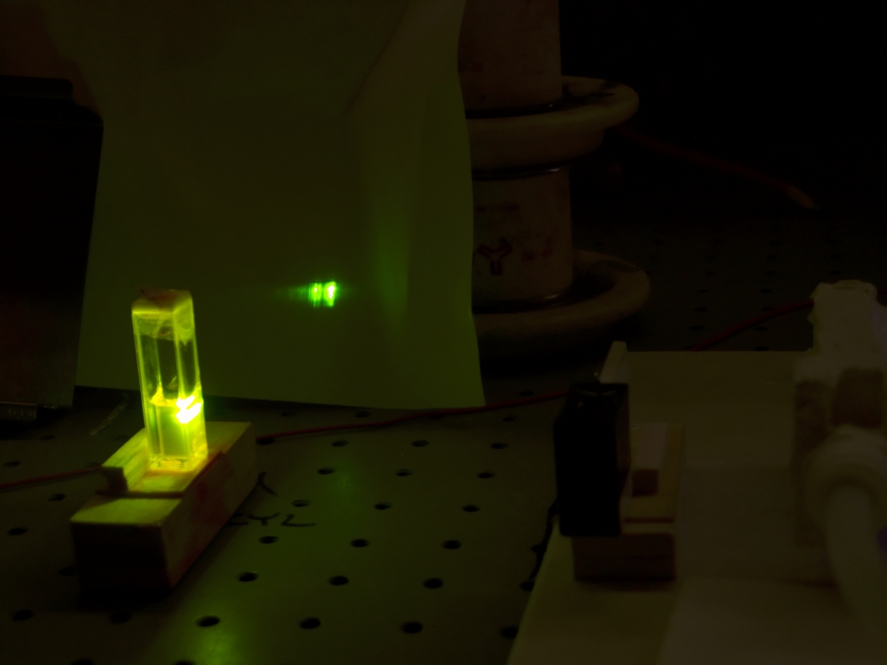
(I took the time to clean up the bad pixels in this photo so they wouldn’t distract from the information. The lights were dimmed so the shutter would stay open longer, giving me a better chance of actually capturing one of the pulses.)
It is difficult to measure the pulsewidth of this laser because of the large EMP output (see photo), but my first attempts appear to indicate FWHM that may be more than 10 nsec. I will be trying to verify that, as the trace on the scope was seriously distorted, making it hard to read:
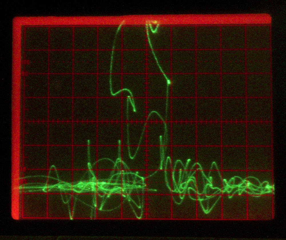
(It is a sobering thing to see curlicues on the face of a Tektronix 7104; the trace just is not supposed to cross over itself.) That’s 10 nsec/box, btw, with a Motorola MRD500 photodiode [1 nsec or better risetime] feeding a Tek 7A21 vertical amp [1 GHz bandwidth]. Argh.
The laser seems to operate well with a mixture of nitrogen and helium, across a fairly narrow pressure range; as far as I can tell, best operation seems to occur at about 300 Torr with about 35 kV coming from the power supply. This pressure is higher than I would expect, but probably more than half of that is helium, so the partial pressure of nitrogen is likely to be close to 150 Torr, and may be less. (My gas supplies are not calibrated for N2 or He, so I can’t really tell how much of each gas is present. Fortunately, I do have flowmeters, so I get a relative indication, and I can set things fairly consistently.)
[Late that night]
I took the scope outside into the hallway, plugged it into power from another room, changed the lead that runs from the battery to the photodiode (it was not coax), ...and still couldn’t get a well-behaved trace on the scope. I did, however, see enough pulses to get a good sense of relative performance, and I now have things at least partially optimized. Best operation still seems to be at ~300 Torr, with the nitrogen meter showing just a little higher than the helium one, though that is still a bit iffy. Pulsewidth looks like it varies somewhat, and the scope trace was not reliable, but I would guess that it is the usual 8 nsec or so. This is unsettling: I would have expected (and would much prefer) at least 12 nsec; but there may be other optimizations I can perform that will move things in that direction.
I should note (and will try to remember to echo this elsewhere) that getting some kind of visual representation of the output level is crucial to optimization. You cannot tell much about how bright a dye laser is by looking at the spot on the target, and you can confuse yourself very thoroughly by trying (for example) to vary the position of the dye cuvette in an effort to guess at what adjustments have which effect on the power of the nitrogen laser. Having a power meter or some way to display the output on an oscilloscope is more helpful than you can imagine.
The preionizer seems to increase the output a little, but I did not scope it. It is now 1 am, and I have stopped for the night. Also, one of the little doorknob caps in the preionizer power supply is sparking, and needs to be swapped out.
At this point I am getting very good lasing from the
cuvette of Fluorescein, and tomorrow I will probably
check to see whether I can get a spark if I focus
the output onto a piece of steel. I will also attempt
to get the rear mirror adjusted, though if the sparks
in the discharge are occurring early enough, they
may interfere with that. (I begin to think I may
need to build yet another head for this laser.)
(23 March, 2007)
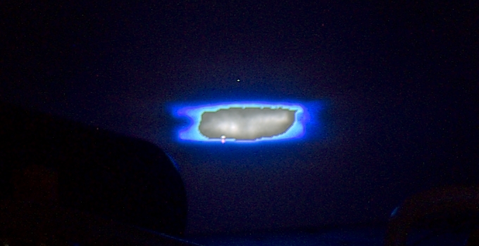
Here are some photos. In the first one, you can see the
fluorescence caused by the beam when I put a piece of
paper in front of the laser. The funny gray area in the
middle seems to be caused by the intensity of the light;
even though it was actually blue, it has apparently
managed to excite all 3 colors of pixel in the sensor.
(This photo was taken from a greater distance than the
others, and I may redo it at some point; the
“6c” size is a direct crop, so I don’t
have anything larger at this time. There are several
artifacts; they are bad pixels in the sensor, which is
now more than 4 years old. There is also a certain amount
of general noise in the image.)
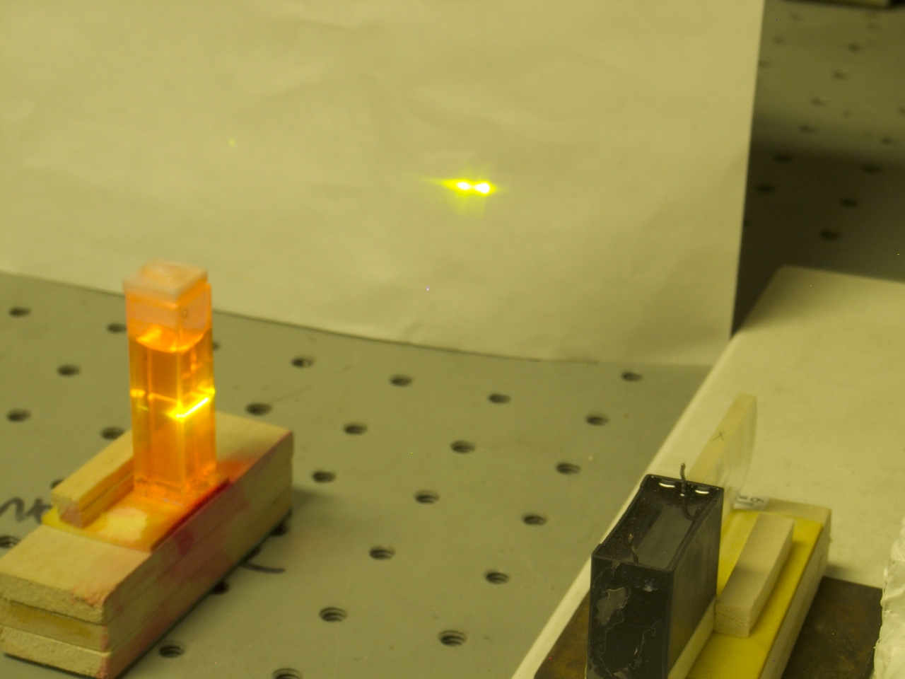
The second photo shows a cuvette of Rhodamine 6G with
the beam nicely focused on it by a cylindrical lens.
As you can see, it is lasing nicely.
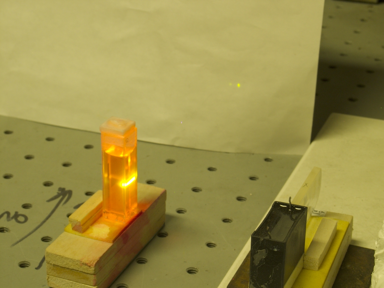
The third photo shows the same cuvette with the beam
significantly out of focus. (Note the height of the
bright stripe on the front of the cuvette, and compare
the position of the cuvette on the benchtop in this
image with the position in the previous image.) There is
enough power that the R6G is lasing anyway. This is a
loose but convenient test of power: if a good dye will
lase only when the beam is focused very tightly, the
laser is obviously less powerful than one that will lase
the dye unfocused or only slightly focused. This laser
will not lase the dye without at least some focusing; my
suspicion is that it takes close to 1 MW peak power to
do that. Again, however, I will note that only a bit
less than 1/3 of the beam is actually hitting the dye
solution.
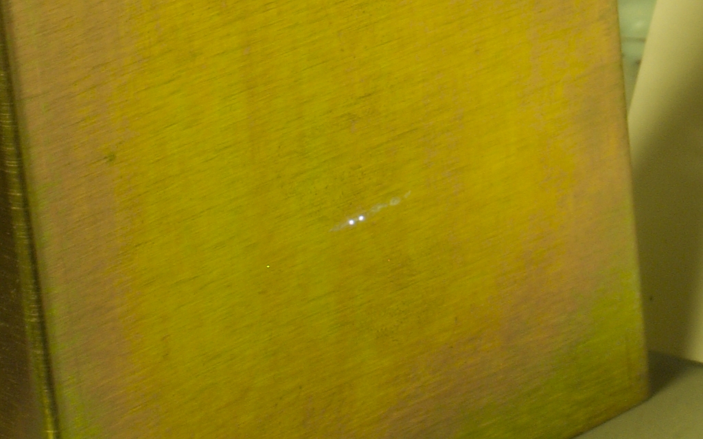
The final photo shows what happens when I focus the
beam (using a fused silica lens) onto a piece of steel.
This generally indicates peak power of at least 200 kW,
but in fact the sparks appear to be bigger than the ones
I got with my previous laser, which was putting out
nearly 240 kW at the time. Also, I get sparks with the
steel surface at a wider range of distances from the
focusing lens than I did at 240 kW. (Note: The small
white spot that you can see, a bit to the left of the
two sparks, is a defect in the camera’s sensor.)
To give you a sense of scale, the two sparks are
probably about 4 mm apart, give or take a bit.
It is clear that the laser is providing at least
decent performance. I have now measured the pulse
energy, which is (unless I have goofed) 2.6 mj.
If the pulse is 10 nsec long, that gives me an
average power of 260 kW, and a peak power that
is probably close to 360 kW. It remains to be
seen whether I can optimize things further, to
reach the design goal of 500 kW peak. (If the
pulse is shorter than 10 nsec, of course, I am
already getting higher power.)
In the meanwhile,
Milan Karakas
has suggested that I hang a grounded screen in front of
the laser to help reduce the strength of the EMP that it
generates when I fire it. This strikes me as an excellent
idea, and I intend to put it into practice.
[Added, 06 January, 2009]
If I decide to rebuild this laser, I will almost certainly
use a mixture of water and glycerol as the dielectric. If
you want to make one of these, and you do not have access
to low-conductivity water, or to the materials it takes to
make low-conductivity water from (for example) distilled
water, you can probably just use glycerol. You will have
to work around the high viscosity.
Another point is that the vertical orientation of the
water-cap is suboptimal, as there is the potential for
an arc across the surface of the water, near the top, if
the capacitor is not completely filled. Having the
water-cap in a horizontal orientation risks trapping
bubbles between the stainless steel plates, but even a
slight tilt (with some tapping after the cap is first
filled, to jar the bubbles loose) should be viable.
Alternatively, I can tilt the cap just a little, so that
bubbles travel to the top corner, and if I add a
sight-glass at that corner I will know when I need to
add water.
If and when I do decide to rebuild this laser, I will
add a second page to this one.
To a set of references to significant articles about nitrogen lasers
One additional reference, with information about liquid
dielectrics:
N. S. Rudenko and V. I. Tsvetkov
This is a wonderful article, translated into English, and
is well worth reading for insights into liquid dielectrics
and Soviet-era physics research.
To the first page in this set, a general discussion
of the issues involved in designing and building a
high-performance nitrogen laser
To a page about my initial effort to produce a
high-performance nitrogen laser
To a page about my continuation of that effort,
which resulted in a laser that puts out about 100 kW and
can operate without a vacuum pump
To a “How-To” page about that laser
To an interim page about my effort to scale up a published design
in order to enhance its performance
To a page about my recent (starting mid-August, 2006)
redesign of the “DKDIY” laser,
which resulted in significantly enhanced performance
To a brief “How-To” page
about building the revised design
To a page about my current (late 2006) effort
to build a less-expensive laser with even better performance
To the Joss Research Institute Website
To my current research homepage
My email address is a@b.com, where a is my first name
(just jon, only 3 letters, no “h”), and b is joss.
My phone number is +1 240 604 4495.
Last modified: Wed May 10 14:57:31 EDT 2017
Further Considerations
Links
Study of the Pulse Electrical Strength of Some Liquids
Soviet Physics — Technical Physics, Vol. 9 No. 6, December,
1964, pp. 837--839
This work was supported by
the Joss Research Institute
Contact Information: