(27 October, 2005, ff)
This page details the construction of a nitrogen laser that is a follow-on to a design published by Peter Schenck and Harold Metcalf in Applied Optics in 1973. Their laser used a set of “doorknob” capacitors for its peakers (which were, unfortunately, referred to in their article and a few other articles as dumpers), and had electrodes about 1 meter long. It developed up to about 160 kW peak power at 15 kV. The design was easy to build, and provided very reasonable performance.
In view of current information, it should be fairly straightforward to scale their original design up by a factor of 2 to 4 in output power without sacrificing ease of construction and operation; this page is about my effort to do so. It is a developmental page, so you can expect lots of false starts and failures along the way. If and when I have the laser up and running the way I want it to, I will create a new page, just as I did for my previous laser, which was a voltage-doubler circuit, also using doorknobs, that developed a little over 100 kW at about 20 kV. That laser had a channel that was about 45 cm long, considerably shorter than the channel of the Schenck and Metcalf laser, which at least partly accounts for its reduced performance. The laser developed in this report has active length of slightly over 1 meter, channel width of about 35 mm, and channel depth of about 3 mm; it is driven by a main store of 89 nF, charged to ~30 kV and switched with a commercial triggered spark gap (EG&G GP-32B), though a homebrew spark gap should work as well, provided it is triggered and is of a low-inductance design.
(15 August, 2006)
Having constructed and then revamped this laser,
I am returning to the previous laser to further my
understanding. I hope to learn enough to build a
second version of this laser that outperforms the
first version by a considerable margin. Most of this
page describes my design ideas and then my trials
and tribulations with construction and operation...
1. This laser uses high voltages, and capacitors that can store lethal amounts of energy. It puts out an invisible ultraviolet beam that can damage your eyes and skin. It is important to take adequate safety precautions and use appropriate safety equipment with any laser; but it is crucially important with lasers that involve high voltages and/or produce invisible beams!
2. When you fire a laser that stores substantial amounts of energy and discharges that energy in a very short time, you generate a sharp electromagnetic pulse. This pulse radiates out from the laser circuitry, and can damage equipment that is connected to the laser, or even close to it. I always put one or more large inductors “hot” line from the power supply, and I also put one in the ground line. If you are attempting to measure the output of your power supply with a voltage divider, put a smaller choke in each of the wires going to the meter, as close to it as possible. You probably also want to put a small capacitor directly across the meter input, as an additional “snubber”.
(I should note that I have actually damaged equipment
with the EMP from a laser of this sort, which is how
I know that it can happen.)
The design presented here is built with laser-grade SrTiO3 doorknobs, which have lower inductance than the TV-grade capacitors that Schenck and Metcalf used, and which sustain their capacitance better as the applied voltage increases. It also has significantly larger main storage (the initial plan called for 60 nf). Both of these factors should provide slight increases in output energy and power. In addition, even if no other parameters were changed, the higher voltage should cause some increase in the output power and energy. (Unfortunately, because increasing the charging voltage makes very little difference in the voltage at which the channel starts to conduct, and also because of the short time during which the laser is active, doubling the charging voltage is not likely to produce the factor of 4 increase in power that one might naïvely expect.)
The design is intended for higher partial pressure of nitrogen, which provides more nitrogen molecules and thus makes it harder to saturate the gain, and I will be filling it with a mixture of nitrogen and helium, which has been shown to improve the operation and stability of low-pressure nitrogen lasers.
Because spark gaps switch significantly faster than thyratrons, I have elected to use one as the switch in this design — my concern here is for convenience and peak power, rather than for high repetition rate or average power.
In principle, this design should be capable of up to
about 500 kW output; but my experience has been that while
it is trivially easy to build a nitrogen laser, building
a high-performance nitrogen laser is extremely
difficult. 500 kW is probably a reasonable lower
bound for the high-performance regime for low-pressure
N2 lasers; I am not expecting to obtain more
than that from this design even after optimization, and
it will probably produce considerably less than that at
“first light”. [Note, added in proof: in
fact, that is exactly what happened. Photos below.]
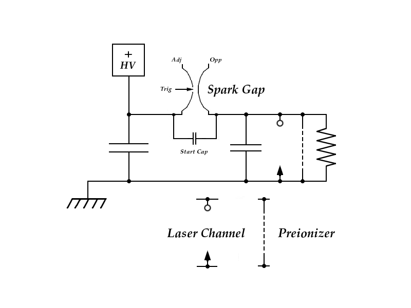
Here is the circuit diagram of the laser:
The capacitor labelled “Start Cap” is present mostly in order to produce a current of a few dozen Amperes in the spark gap very quickly when it is triggered, to help develop a substantial conduction channel in it. This is perhaps less important in a Charge-Transfer design than it is in a voltage-doubler circuit, but it is nonetheless a real issue. The manufacturer recommends pushing at least 10 Amperes through the gap to get it to switch properly.
I have shown a charging resistor across the channel. This insures that the full charging voltage will appear across the spark gap. It also insures that there won’t be any voltage across the peaker caps when the laser is not in use. It is a good idea to put a very large bleeder resistor across the dumper cap as well, for safety. Even 200 MΩ is okay, just so the cap will slowly discharge to a safe level.
I’ve shown a formal preionizer in the schematic and in the preliminary layout (next diagram), but I will probably build the first version of this laser without it. Note that various “nuts and bolts” (including the start cap) are not shown in this diagram.
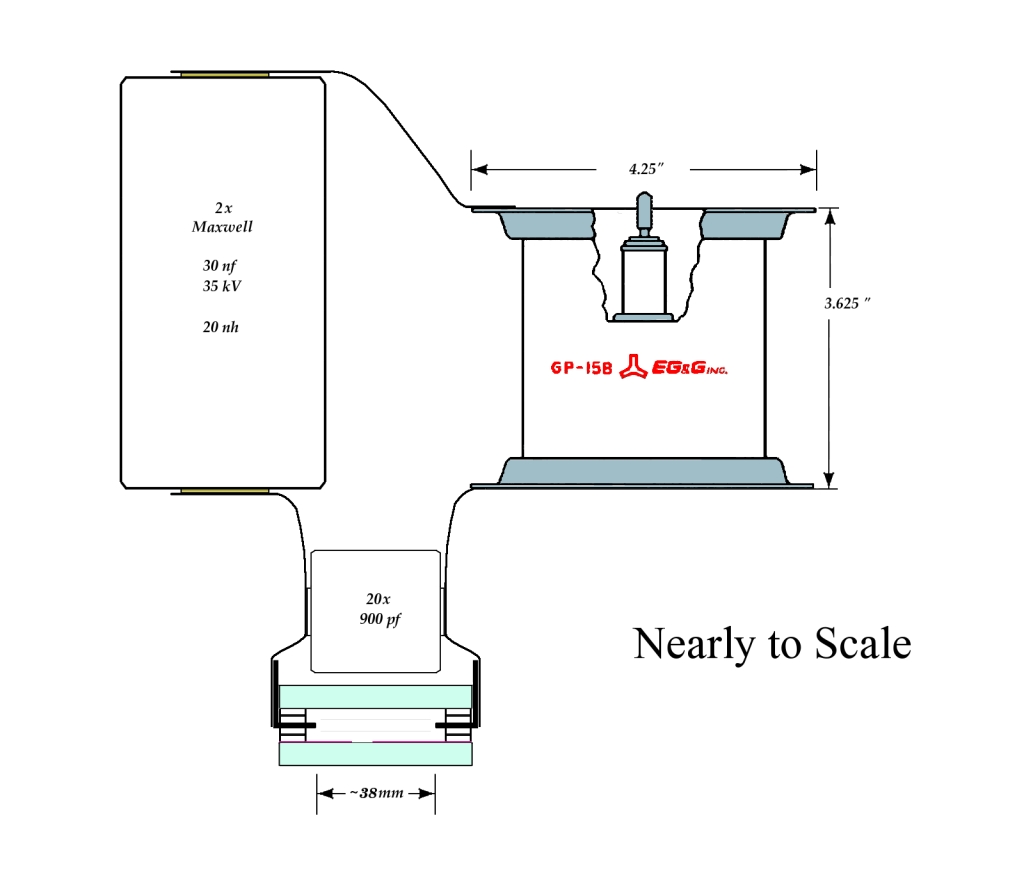
(Click for a 1024-x-896-px enlargement.)
The glass sidewalls of the channel are 2.5" wide, and 48" long. The electrodes are likewise 48" long, but the capacitors are restricted to the center 40". This should help avoid sparking at the ends of the electrodes, where the longer current path provides higher inductance. I don’t know how much of this effect I will see with doorknob caps, which have relatively high inductance to begin with, but every little bit helps. (I will also be rounding and polishing the ends of the electrodes, also to discourage sparking.)
Notice that the electrodes are aluminum angle extrusion, and that they and the glass walls provide the stiffness that holds the channel straight. This is in contrast to the Schenck and Metcalf original, which was built on an aluminum plank. The spacers are ABS plastic I-beam from the hobby shop. (I looked for fiberglass strip, but failed to find anything of an appropriate size.)
Here’s a detail of the electrode positioning (which is symmetric, so I’ve only drawn one) —
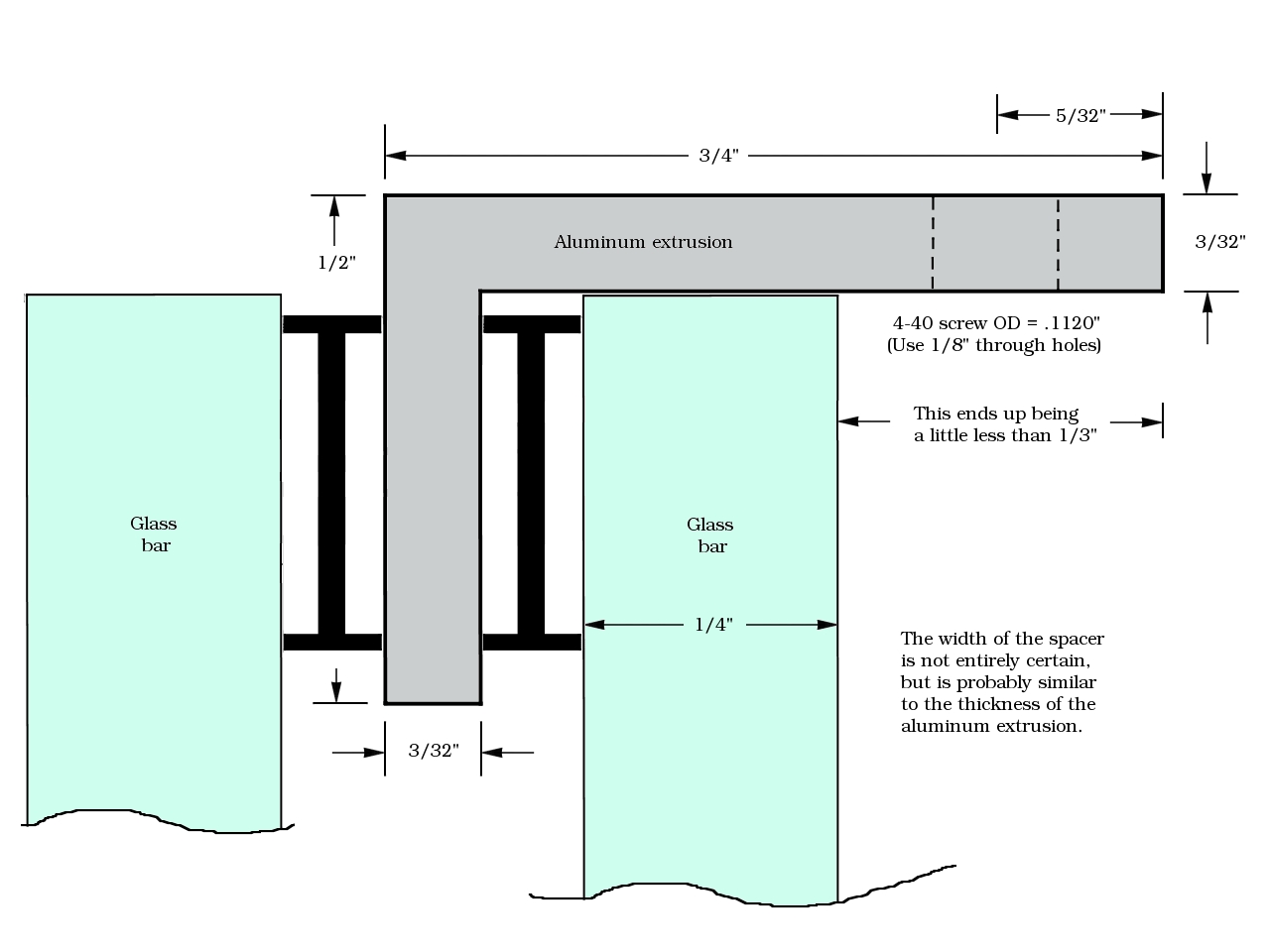
(The enlargement is 1280x960 px in this case.)
The spacers, btw, are probably not precisely drawn to scale, but they are close enough for folk music. Also, I have drawn the 1/8" holes a bit closer to the glass than they actually are: in order to leave room for hex-nuts, I am drilling them 1/8" in from the edge of the extrusion.
The next task is to determine which face of the glass was in contact with the tin bath during manufacture, so that I can decide which face goes toward the laser channel. My early thought is that the tin face, which is slightly conductive, may provide some preionization, and should face inward, but I may change my mind. In either case, I want to know which face is which. (It occurs to me that perhaps I should build this thing so that it can be disassembled fairly easily.)
[Note, added some time later: I resolved the tin issue
at the beginning of May, 2006. It is covered elsewhere
on this page.]
(18 December, 2005, ff)
An initial test using air at room pressure failed to discriminate between the faces of a sample of float glass. I will either ignore the issue, or think up an easy way to test at reduced pressure and with other gases. (That turned out to be unnecessary; see below.)
Meanwhile, I figured out a reasonable way to drill the holes in the aluminum extrusions and brass shim stock, and I have begun that part of the project. I am attempting to do this using only hand tools, as it is clear that not everyone has access to a machine shop; for this part of the drilling, I have clamped the two extrusions down to a piece of plastic 1x3 with the shim stock between them. (I would present a photo, but my camera is in the shop. I’ll see if I can borrow a camera to make it easier to understand this. In the meanwhile, here is an ASCII diagram. This is an end view, not quite to scale...)
     +---+
     |  |
     |  |
     |  |
     |  |
     |  |                       V
     |  |
     |  +-------------------------------+
     |                                  |
     +----------------------------------+
     ==================================================
     +----------------------------------+
     |                                  |
     |  +-------------------------------+
     |  |+-------------------------------------------+
     |  ||                                           |
     |  ||                                           |
     |  ||                                           |
     |  ||                                           |
     |  ||                                           |
     +--+|      PLASTIC 1x2                          |
         |        used as                            |
         |        support                            |
         |                                           |
         |                                           |
         |                                           |
         |                                           |
         +-------------------------------------------+
The row of “================” represents both pieces of shim stock. I am only showing part of the stock here; it is 6" wide, and would extend well off the page to the right. The “V” shows roughly where the holes go, about 1/8" in from the right edges of the extrusions. I have drawn the aluminum angle thicker than it really is, because I didn’t have much choice; ASCII is just not the preferred mode for this kind of thing.
(19/20 December, 2005)
I have now drilled all of the holes indicated in the diagram above, starting at the 4" mark and continuing, one per inch, to the 40" mark. Next, I have to decide on the locations of the peaker capacitors, and drill holes in the shims for them. I will probably use another piece of 1x2 as backing and a [thinner] piece of plastic lath on top of the shims, as it is quite difficult to drill shim stock by itself. (Note, added later: I actually ended up using a piece of acrylic that already had a hole of about the right size in it.) I am currently deciding whether to use 20 peakers, or try to get as close to 20 nf as I can (I have 22 of the capacitors).
(15 January, 2006)
After a brief delay, I am making further progress on this machine, and I hope to have it ready to test within a week or so. I did, indeed, decide to use 20 peakers, and I have drilled the brass shim stock to take them. Here are two views of the drilling setup, without the clamps (I removed them after I drilled a few holes scattered along the electrodes, and screwed the electrodes and the brass shim stock down to the first plastic 1x2):
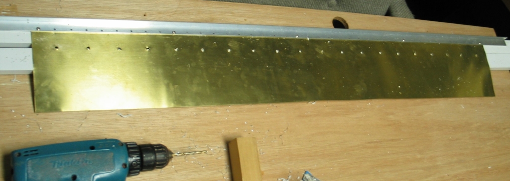
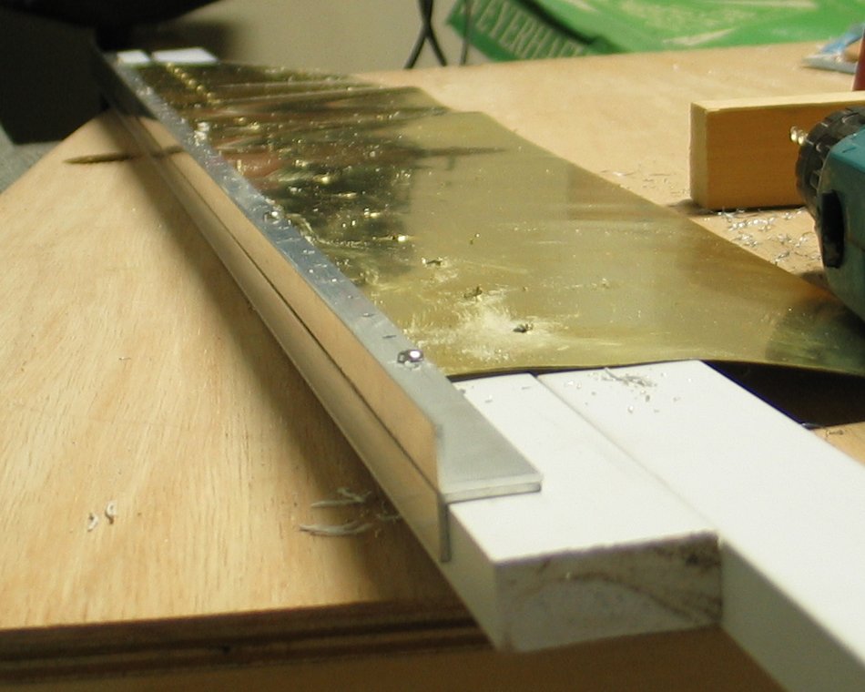
You can see Doug’s trusty Makita-san, which he has lent me, on the workspace. That and my Dremel are the primary tools I’m using to build this laser; I am attempting to keep the use of fancier tools to a minimum.
My next steps will involve shaping the electrodes in a
further effort to minimize sparking; attaching spacers
to keep them away from the glass sidewalls; and building
up the endplates, which were very kindly furnished by
Brooks Moses. The pieces are 1/4" thick, and I need to
put gas ports into them, so I expect to triple them up,
which will give me plenty of thickness to drill into.
Brooks sent 6 of them, so this is entirely feasible.
(While I am obliged to admit that these plates were made
on a laser cutter, it is at least possible to produce
them with hand-tools, so they don’t really
constitute a breach of my principles.)
(16 January, 2006, early AM)
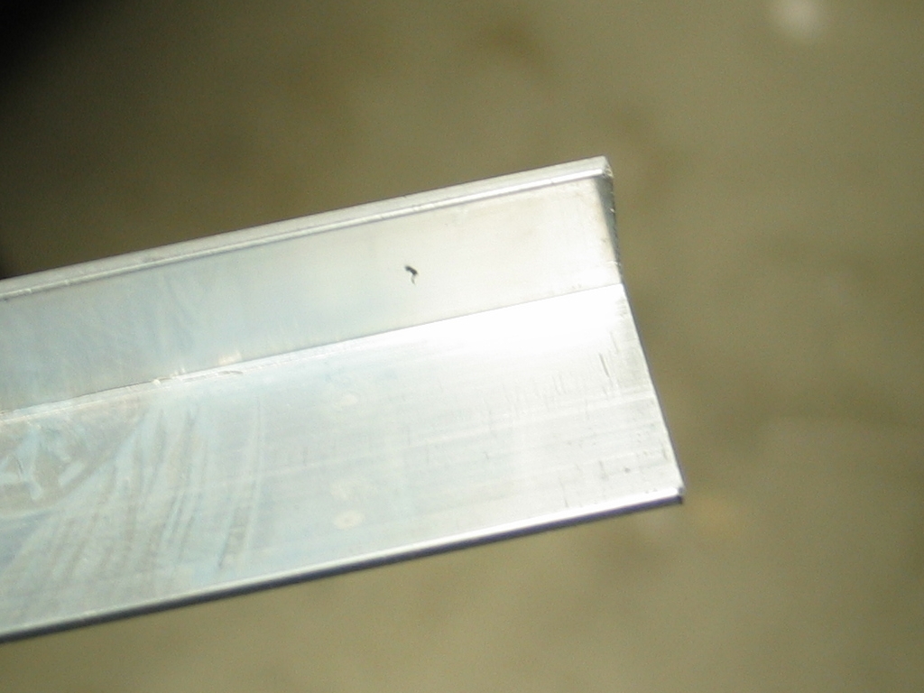
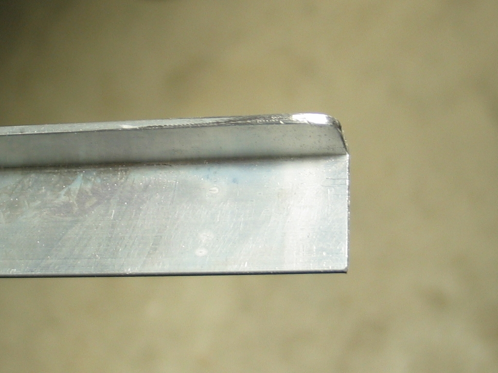
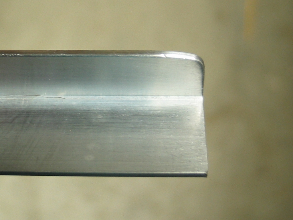
I have shaped the electrodes, and buffed them with
fine stainless steelwool. Here are the “before”,
“during”, and “after” photos:
electrodes as purchased, filed to shape, and buffed —
The surface is neither as smooth as I might like, nor
as free from nicks, but it will probably do. Fortunately,
none of this is horrendously expensive, and I can
fairly easily replace the electrodes if I find that
I need to.
Several parameters appear to be important to nitrogen
laser performance. The most obvious is a design that is
fast enough: lasing tends to begin about 40 or 50 nsec
after the discharge begins to get underway, and
terminates within another 15 nsec or so even in
high-performance lasers (typically 6 to 8 nsec in
smaller devices).
Another useful or interesting measure is the energy
density in the discharge. Here is a brief look at my
expectation for the current design:
From evidence in various articles, it seems reasonable
to guess that the channel will probably arc over at a
maximum of roughly 18 kV, with the gas pressure
optimized. The peaker caps will contain just under 3
joules at that voltage. Some fraction of that energy,
plus some energy from the main store, will find its way
into the discharge in the time before lasing ceases. I
will argue that 3 j is a fairly reasonable amount, with
the main store making up for anything that the peakers
don’t manage to put into the discharge in the
period of interest. (Note that the contribution from the
main storage cap is known to be significant in at least
some designs. See the references, specifically the
Rebhan et al. article, for more about this.)
The active region of the laser channel is about 2.5 mm
wide, 38 mm high (I will call this 40, to be slightly
conservative), and about 1000 mm long, for a total
active volume of 0.1 liter.
This suggests energy density on the order of 30
joules/liter. That’s a bit low for a really
high-performance machine, but it may serve my purposes
here. (I would prefer to be putting at least 50 j/l into
the discharge, but I’ll take what I can get.)
(02 May, 2006, ff. )
I have been holding off on further construction
because I wanted to know which face of the sidewall
glass had been in contact with the tin during
manufacture. The tin side is slightly conductive,
and might help with preionization ...or might not
(it has been reported to cause trouble in one
non-laser application that involves low-pressure
gases and HV), so I am tentatively plannning on
keeping it on the outside, at least for the first
iteration of the channel. On the other hand, it
could help even out the discharge, particularly
if it were on the side away from the peaker caps,
so I may put the tin toward the discharge on that
side and away from the discharge on the cap side.
(Does it seem like I’m vacillating? It should.)
Anyway, to get back to my attempts at discovering
which face has the Sn in it:
I tried doing a spark test at room pressure, in air, but
I couldn’t see any difference between the two
faces of a sample piece of glass. I was thinking about
perhaps doing more tests either in different atmosphere
(helium, maybe) and/or at reduced pressure; but a few
days ago I received the current issue of the Bulletin of
the American Ceramic Society, and while reading it I
noticed an article about float glass in which the
authors were attempting to measure the tin concentration
by means of fluorescence, using two UV wavelengths in
order to distinguish between Sn(II) and Sn(IV). One of
the wavelengths they were using was 337 nm, which
happens to be a particularly convenient wavelength for
people who are working with nitrogen lasers, so
that’s what I used — I don’t care which
oxidation state the tin is in, I just want to know which
face it’s on.
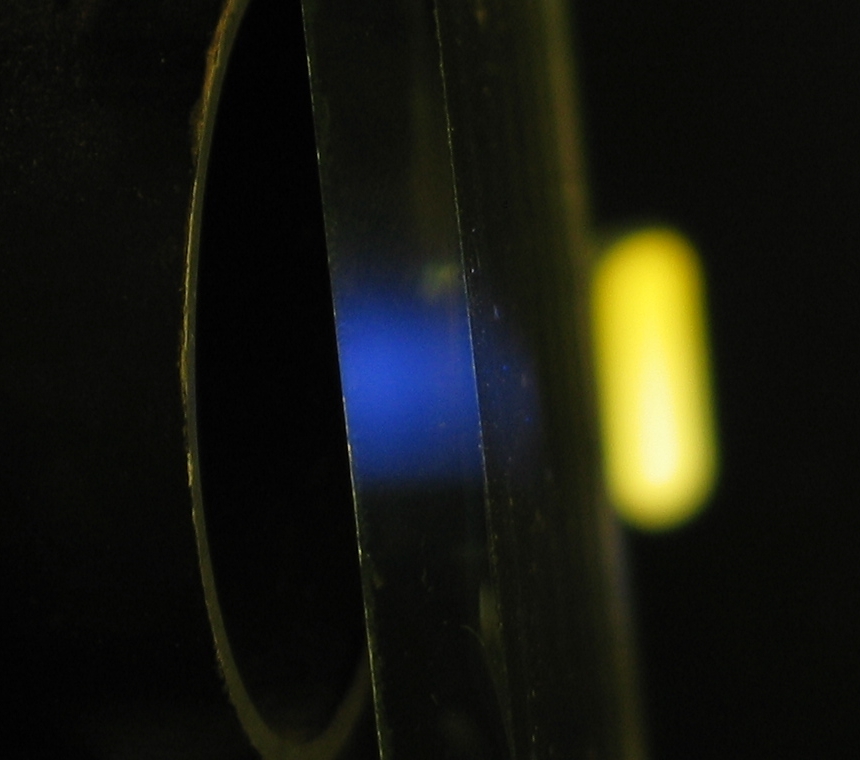
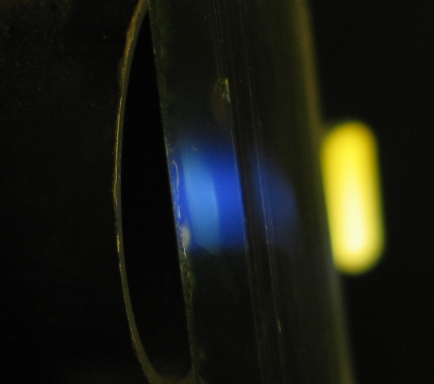
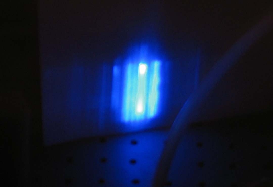
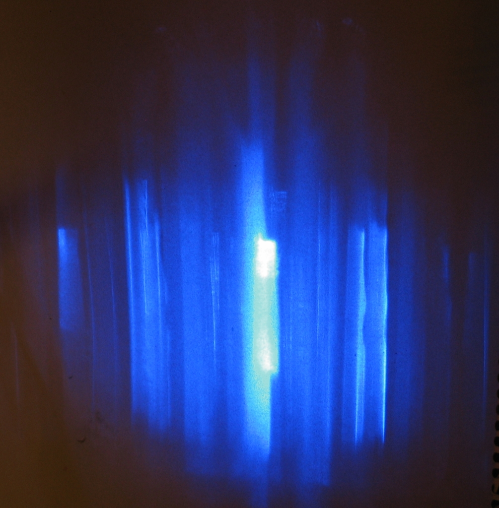
They didn’t mention the output wavelength, but I
figured that if it had been anything truly bizarre they
would have said so. Sure enough, here’s what I got
when I put a piece of ¼-inch-thick glass in front
of the Molectron nitrogen laser:
This seems quite unequivocal to me; the fluorescence of
the tin side is very easy to see (right photo). My next
step is to attach the spacers to the sidewalls, after
which I should be able to assemble the laser channel.
Mind you, I’m kicking myself because I
didn’t think of this test on my own, even though I
observed the fluorescence of the bulk glass (left photo)
while checking it as a possible beam attenuator during
other work.
[Note, added 12 May: Last night I checked with a
mid-wave UV lamp, and I find that if I am careful I can
tell which side has the Sn in it — both faces
absorb the mid-wave (~313 nm) UV fairly sharply, but one
fluoresces brighter than the other. I will probably
repeat the test with an ordinary blacklight, to see
whether that also works.]
As of about 14 May, I have the ABS spacers attached to
the glass. I did, indeed, put the tin face of the
outboard wall and the nonconductive face of the inboard
wall toward the discharge. This may help stabilize the
discharge, if I am very lucky. If I am only moderately
lucky, it won’t interfere with the operation of
the laser.
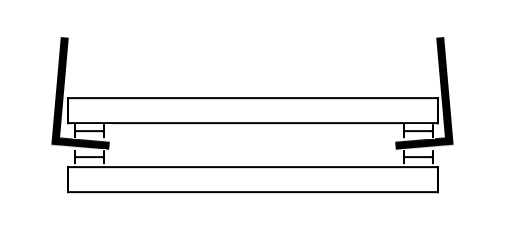
In the meanwhile, I am looking at ways to hold things
in place while I glue the channel together. I have
tried Velcro™ strips, but because of the structure
of the electrodes, the strips pulled them out of
alignment. Here is a crude diagram, in which I have
exaggerated the misalignment so you can more easily
see it --
I begin to think that I may have to glue the electrodes
to the little ABS “H” beams using
cyanoacrylate (“CA”) at the same time as I
seal the gap between the electrodes and the glass with
silicone rubber caulking, and that I will do one
sidewall at a time; but I’m not quite sure
yet. Have to satisfy myself that this is a viable
approach. It becomes an issue because one of the
electrodes is slightly bent, and if I just fit things
together loosely, the width of the channel is uneven.
(19 May)
The Redoubtable LisaJulie Peoples and I have started
the gluing process. I cleaned everything off, ran a
bead of silicone rubber caulking into the angle of
each of the electrodes, and put dots of slow-setting
cyanoacrylate onto the ABS spacers to hold things in
place before the RTV (silicone caulk) had time to set.
(That was almost certainly unnecessary, btw.)
Then we put the thing together and clamped it. Perhaps
expectably I had gotten slightly too much RTV in some
areas, and it squeezed out, getting itself onto the
faces of the electrodes in the process. I am hoping to
clean it up later tonight, after it has had time to
become reasonably firm but before it fully hardens.
If you build one of these, be careful to lay down a
relatively narrow bead of RTV, no more than is necessary
to achieve a good seal!
(Note, the orientation here is upside-down as compared
with the diagram just above. The white plastic bar is
there to hold the assembly up off the benchtop, so that
the electrodes don’t get pushed out of alignment.)
The rails seem fairly straight on casual inspection,
and I hope that they will form a clean discharge. If
not I may be able to disassemble this head and rebuild
it, or in the worst case I can make a new one. It’s
not a difficult design, and of course that is my
intention here: to provide high-performance designs
that people can actually build without making themselves
crazy or spending lots of money.
(20 May, early AM)
I cleaned up the excess glop and caulked the other glass
wall in place. At least one electrode is not quite
straight, but my guess is that the variation is slight
in comparison with the channel width, and furthermore
that it isn’t too likely to cause trouble in any
case — the channel is slightly wider in the middle,
where the discharge would probably be trying to initiate
first; maybe this will even it out a bit. (Again, the
worst case is that I just have to build a new head; but
I am hoping to get good information out of this one,
even if I don’t get particularly superb performance.)
(Later, that evening)
I have begun to modify the ends, prior to installing
them. One of the electrodes is slightly longer than the
glass sidewalls (my error — should have had the
glass shop make the sidewalls 49 inches long, rather
than 48), so I have made room for it. The other slices
are an effort to prevent the current from simply
tracking along the wall.
I still need to figure out how to get the gas into and
out of the laser, which will have to happen through
these endplates; they are not thick enough to drill and
tap, even with the smallest pipe-tap I own, so I am
going to have to Do Something Different. Not yet sure
what that will be, but the chances are good that it
will be relatively simple.
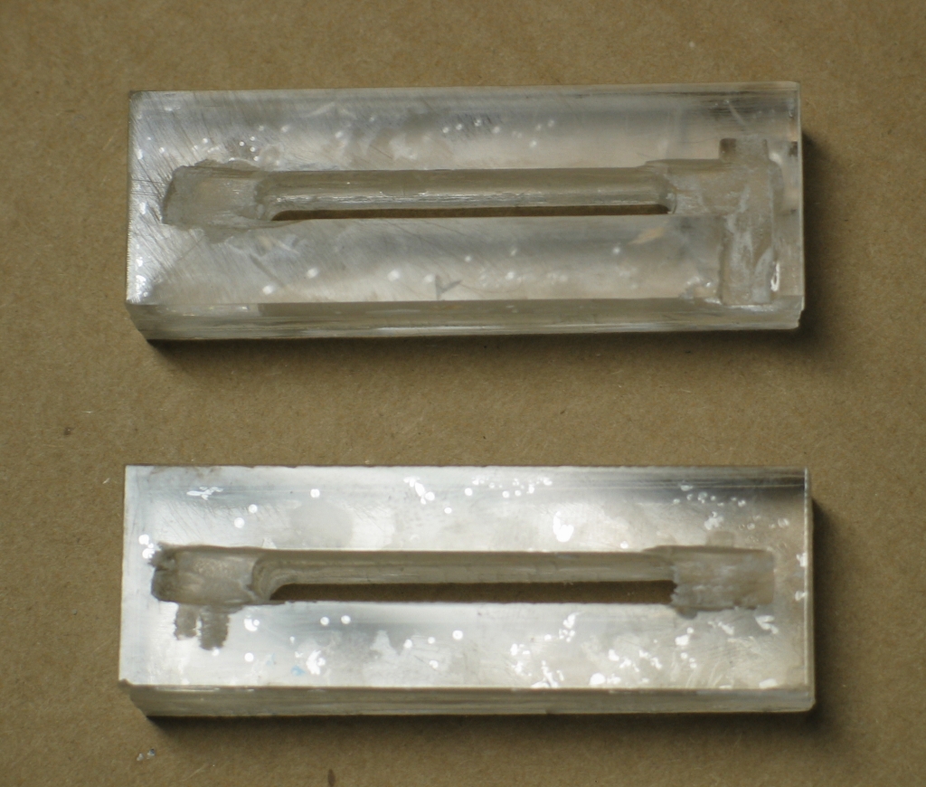
The endplates, as mentioned above, are laminated
acrylic, built from 6 pieces sent to me by Brooks Moses.
I glued them together in stacks of three, using
cyanoacrylate (“CA”) glue. Some cracks (not
easily visible in this photo) developed; I am not sure
whether that is more closely related to the grade of CA
glue I used, or the isopropyl alcohol I washed the
pieces with before I glued them. In any case, I will
probably coat the exterior edges with caulking (or more
CA) to minimize leakage through the cracks. The bubbles
between the layers that are visible in the photo
probably aren’t going to be a problem; they are
fairly well encapsulated in the glue.
(22 May, 2006)
It occurs to me that I can always enlarge the gas port
holes in the endplates, so I have decided to use the
small tubing I’ve got. I think it’s
polyethylene, but it is nicely flexible because of
its small diameter, and it has standard fittings on
one end of each piece, so I will easily be able to
make the transition to the larger polyethylene tubing
I generally use for gas and vacuum connections.
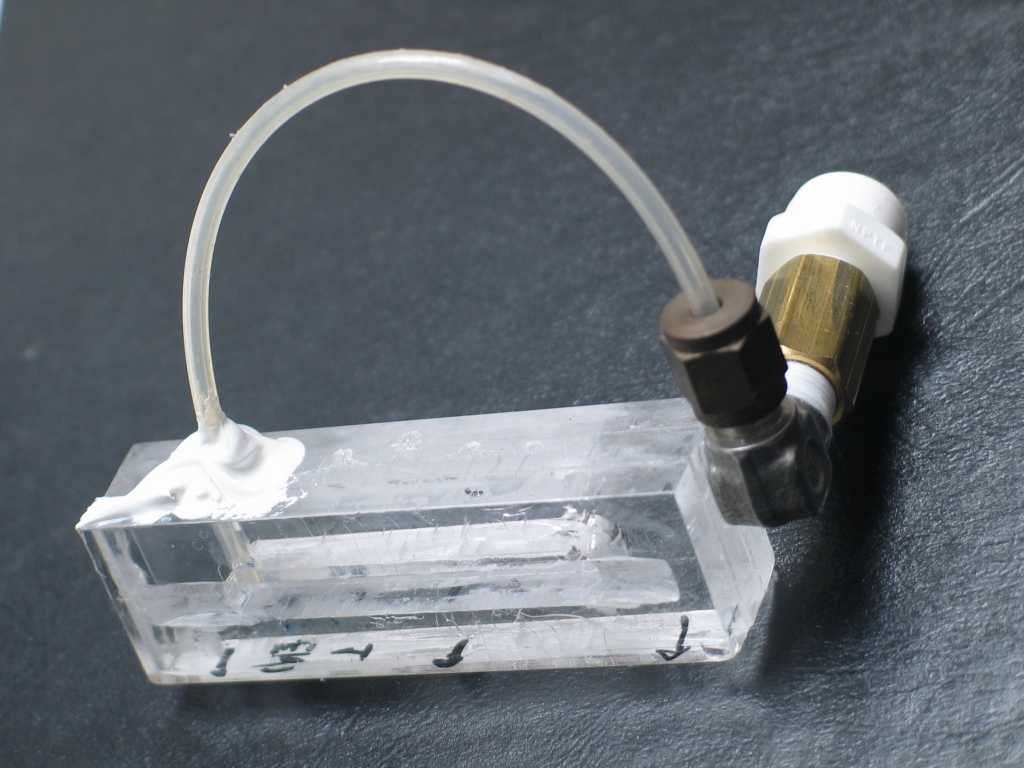
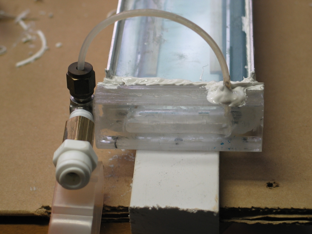
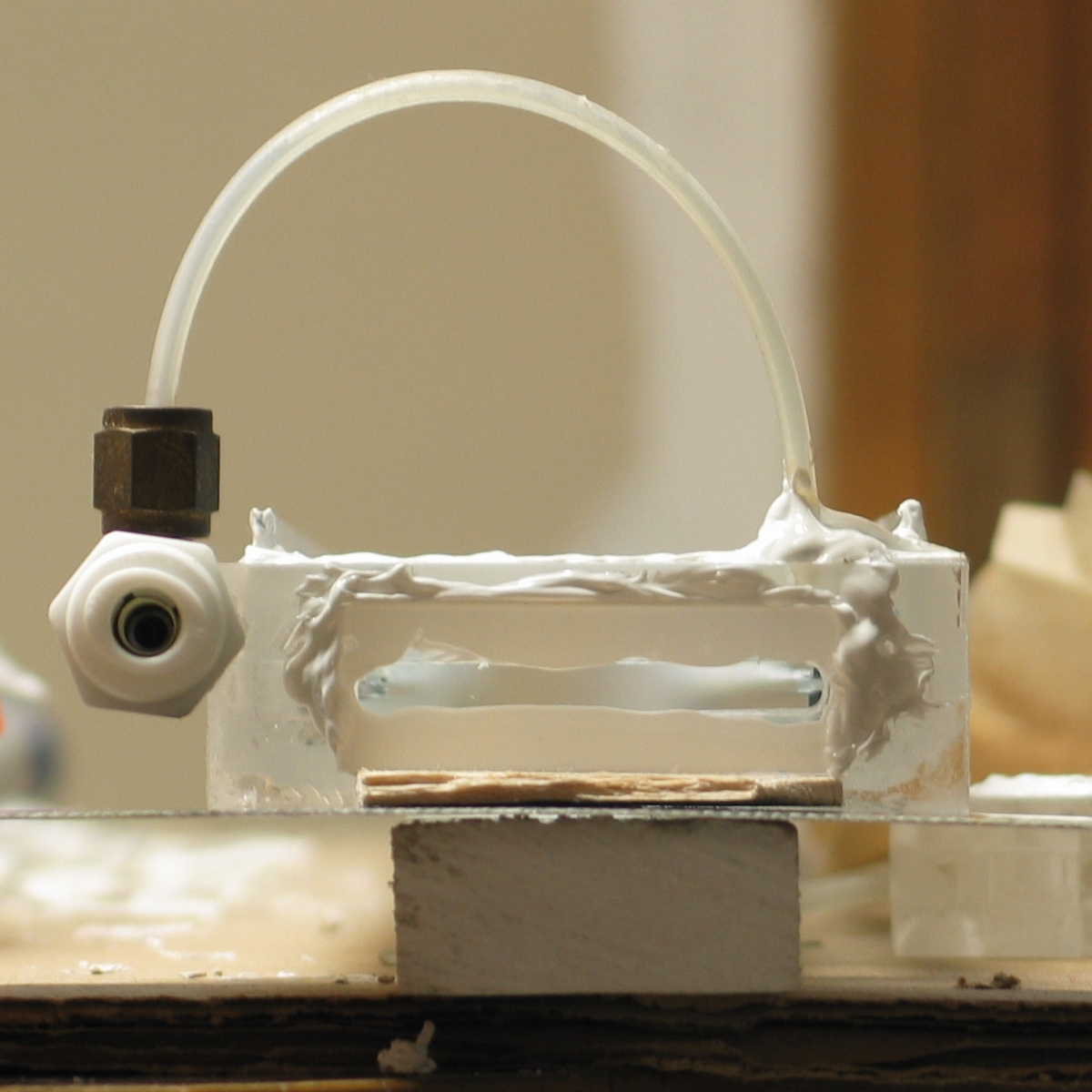
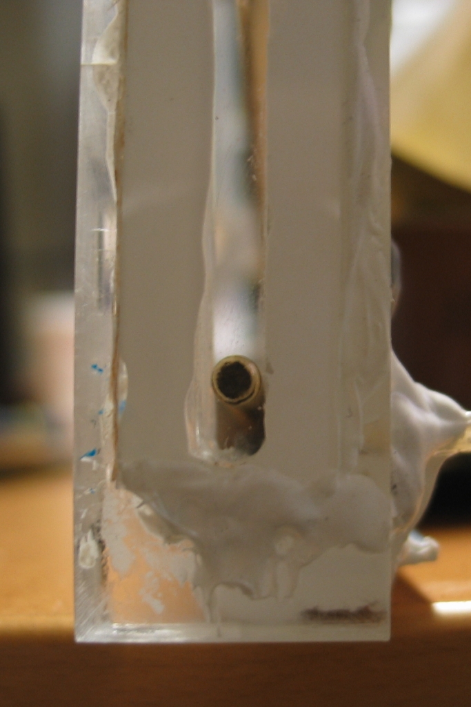
(23 May, early AM)
I have now adapted the tiny hose to the larger
sizes of polyethylene I”m going to use
(¼-inch for the gas inlet, and 3/8-inch
for the vacuum); and I’ve attached the small
tubes, with their adapters, to the endplates:
Once the RTV has hardened I will probably attach
the hose adapters more firmly to the endplates
(they are held on with CA at the moment, just to
keep them in place while I assemble things). Then
I have to figure out how to keep the endplates
in position while I RTV them to the head. After
that, I need to connect up the electrical end of
the operation, and I can start testing. (Even if
the head won’t hold vacuum, I will be able to
test it with N2 and He at room pressure.)
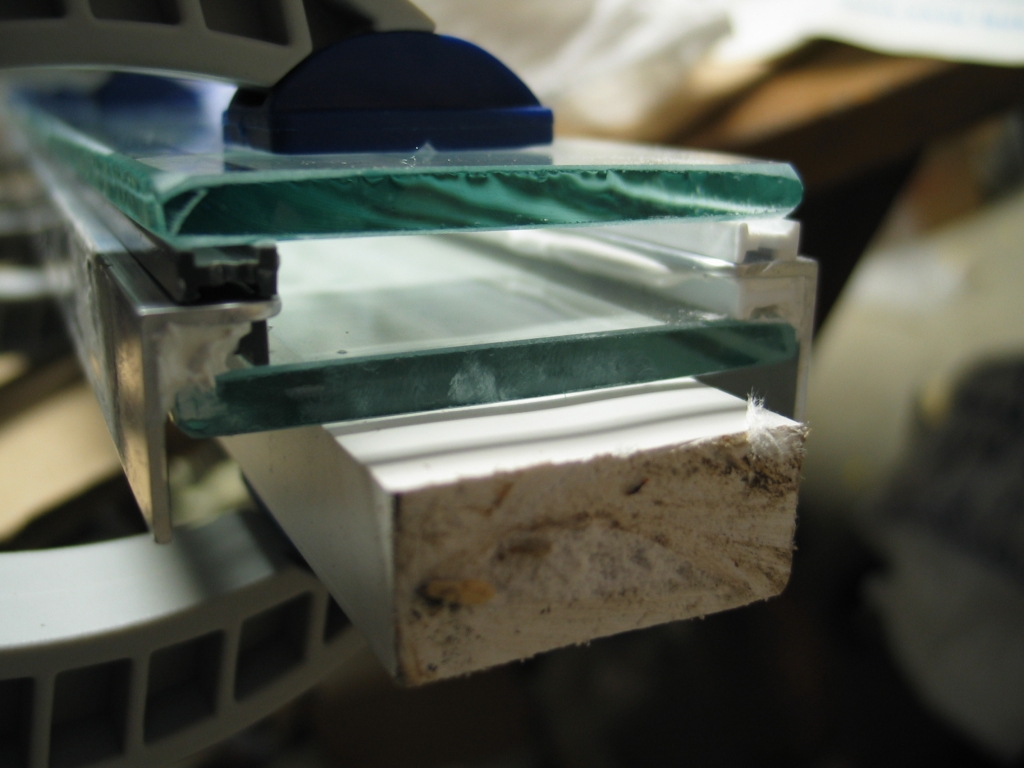
(Later on 23 May)
I have now put one endcap on, and after I took the first
two photos I attached the fused silica windows to both
caps; the photo on the right was taken with the window
in place.
(Evening of 23 May)
After the RTV had set for a few hours I moved the head
until the attached endcap was not above the plastic 1x2,
which let me lift the opposite end and move the supports
closer to it. Then I glued the other cap on. By
tomorrow morning both ends should be reasonably firm,
and by the evening I can probably start attaching the
electrical works. We’ll see how long that
takes. Once the brass shims and the capacitors and the
switch are in place, I should be able to start some
initial testing.
(26 May, 2006, early AM)
I’ve been pestilentially busy for the last
couple days, and have not yet had time to locate
some of the hardware I need in order to assemble
the electrical connections. This weekend is likewise
filled, and I probably won’t be able to start
testing until early next week.
(Addendum, 27 May, 2006)
I think I now have all of the hardware that I will need
to connect the capacitors and switch. I have deburred
the mounting holes in the electrodes, and I have loosely
attached the two long brass shims that connect the
electrodes to the peaker caps and the rest of the HV
components. The next step is to attach the peakers,
and that’s a bit iffy because it involves
bending the brass shims; I don’t want to pull
the electrodes loose or start any leaks...
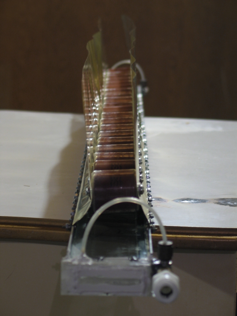
(30 May, 2006, early AM)
I have now put in the peakers, and tightened up the
attachments of the peaker caps and the brass shims:
With luck, I haven’t ruined the vacuum seal.
I have also done rough calibration on a large
Bourdon-tube vacuum gauge, so that I can get at least
a rough sense of the pressure levels inside the laser
when I start using the vacuum pump with it.
At this point, all I have to do is attach the dumper
caps and the switch, and fill the head with helium
to get a first look at the discharge. My guess is
that it will arc someplace, and I’ll have to
rebuild the head, but we’ll see when we actually
get there.
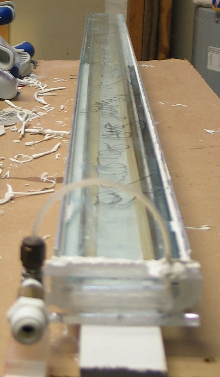
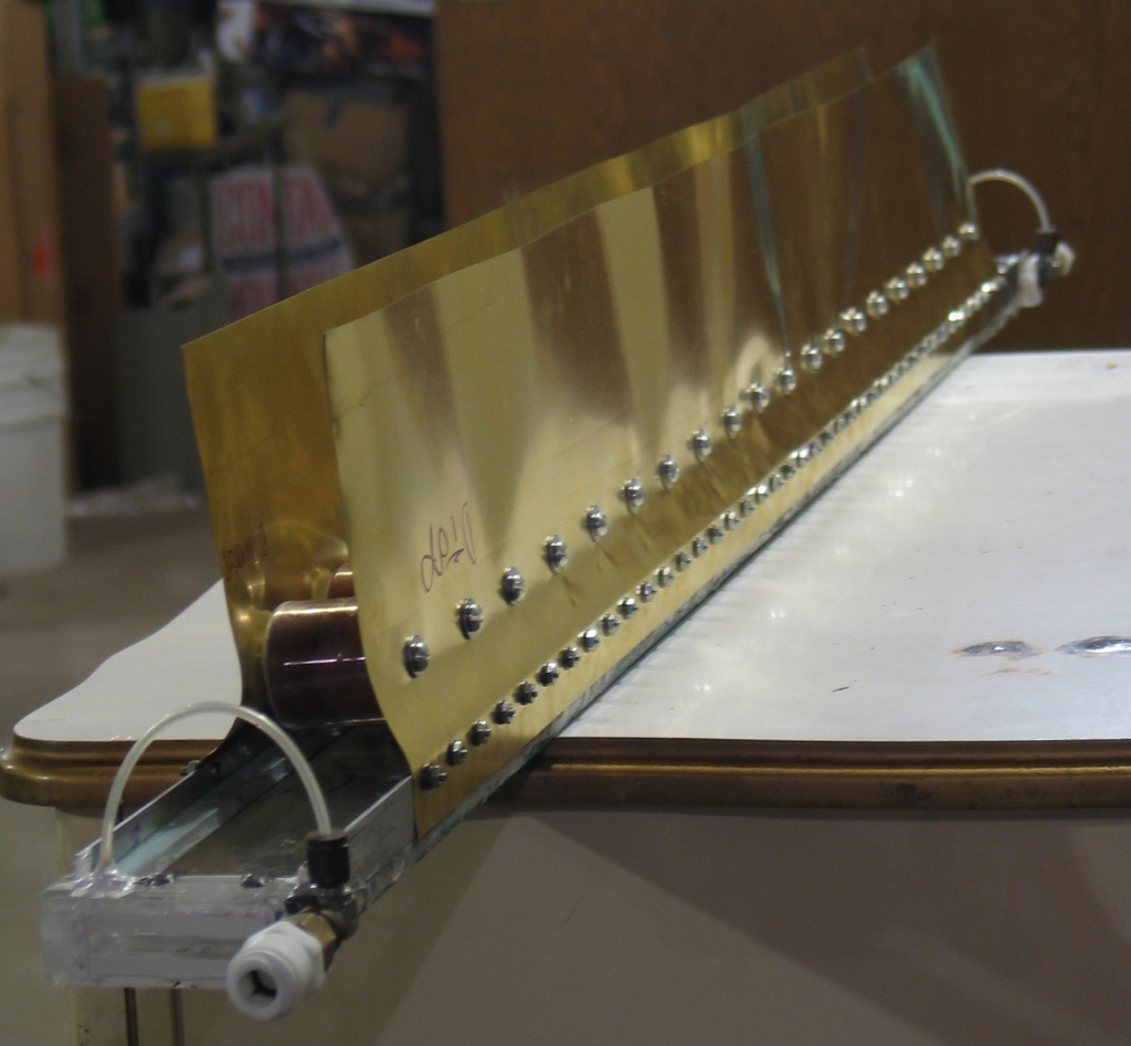
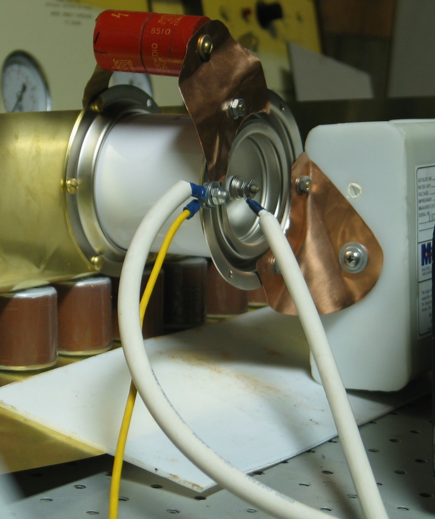
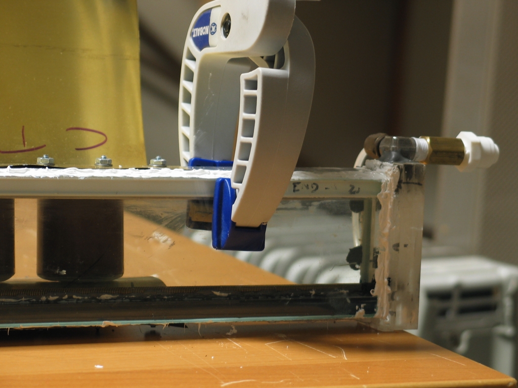
(Morning of May 31, 2006)
A quick check reveals several things:
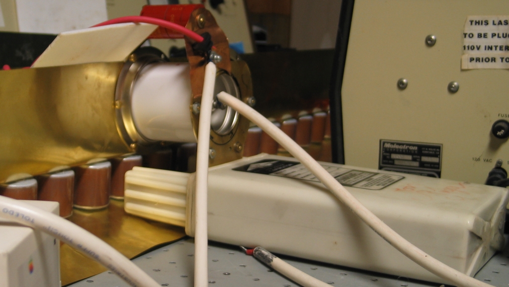
Here is what the center section looks like with
the switch and a single 30-nf cap in place:
This is strictly a testing setup, on a prototype head.
It should not be regarded as a prescription for
optimum performance.
(02 June, 2006)
Leak redux: I did the crudest possible test by blowing
into the vacuum hose with the gas inlet hose valved
off. I thought I felt cool air near the vacuum end of
the head, so I took the switch and capacitor off, and
moved the head to a place where I could see it better.
When I looked at the underside, I found a small gap in
the RTV. I have filled the gap, and when the RTV sets I
will check to see whether I can discover any other
leaks. It is clear that there are no large ones, but I
can’t rule out small ones yet.
I am now leaning toward putting my 89-nf cap on the
laser, rather than the 30-nf cap I was originally
using. This would be slightly slower at the beginning of
the firing cycle, but by the time the channel begins to
conduct there should be lots of current coming from the
cap, which is desirable. Alternatively, I may just use
two of the 30-nF Maxwell jobs, as they are easier to
set up, and I am still at the earliest stages of this.
(late evening, 02 June, 2006)
A short time ago I did a vacuum test, and was very
happy to discover that there do not appear to be any
remaining leaks.
(Early AM, 03 June, 2006)
This device is now officially a laser. It’s a
remarkably bad one, but that’s to be expected at
this early stage. I put it back together with the single
cap (visible in the photo above) about an hour ago, just
to see if I could get it to run, and was very pleased
to find out that it did. I only got lasing at about
the lowest pressure I could achieve, partly because
I was afraid to bring the voltage up too high, but
it’s a start. (I have to confess that I am
extremely pleased. This is the first prototype head
for this design, and tonight was only the second time
I tried to run it. It probably won’t achieve
the design goal, but I am now in a position to figure
out how to get there.)
Once I get the larger main store onto it, I should be
able to bring the voltage up to perhaps 30 kV, and that
should get me somewhat more stable operation. I think
I’m also going to replace the inductor that is
currently across the channel with a resistor, as I am
only seeing a discharge in the channel about one time in
10, which could indicate that the inductor is not
working as well as I’d like. We’ll see
whether the behavior changes when I use a resistor
instead. (The intention is to discharge the peaker
caps between shots so that when I charge up the
main store, the full charge voltage appears across
the switch. Frankly, this probably isn’t
necessary, but the switch works better with somewhat
more than the minimum necessary voltage across it.)
I will also endeavor to take photos of the output on
a fluorescent target, and I will see whether I can
get a decent shot of the discharge. (I’m not
too hopeful about that, as it is not at all bright,
but it may be worth a try.)
(03 June, 2006, afternoon)
I have not yet swapped out the main store, but I
did add a resistor to the inductor across the
channel, which had the desired effect.
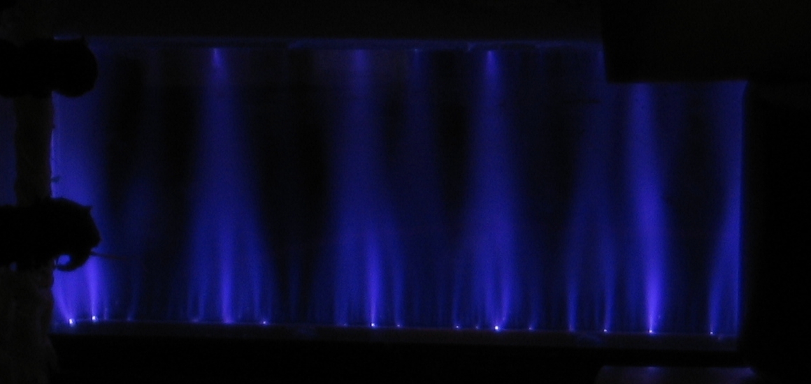
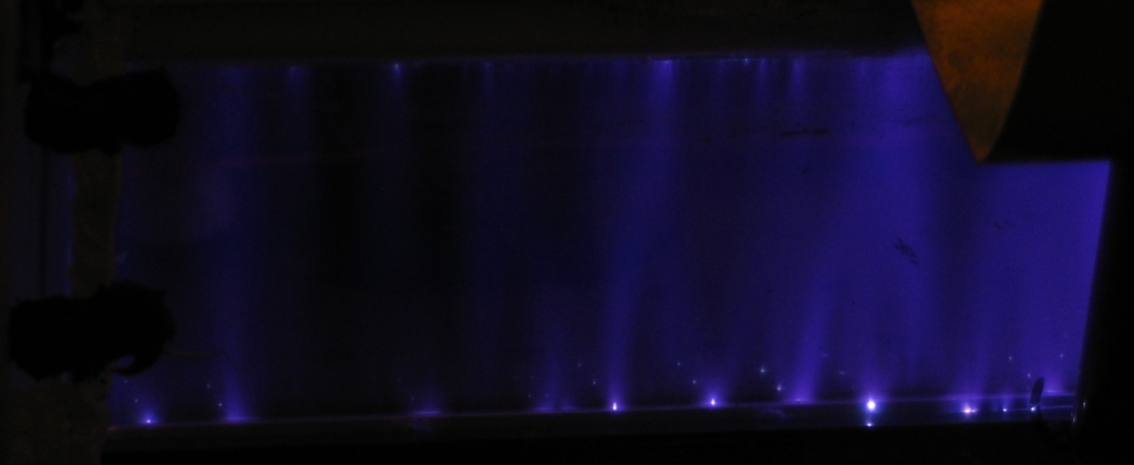
I also took photos of the discharge, which proved to be
considerably easier than I had expected. Here are two
mediocre discharges flanking a failed one:
Note that this is just one end of the head, the
region from the endplate to the first peaker cap.
The view, however, seems to be representative.
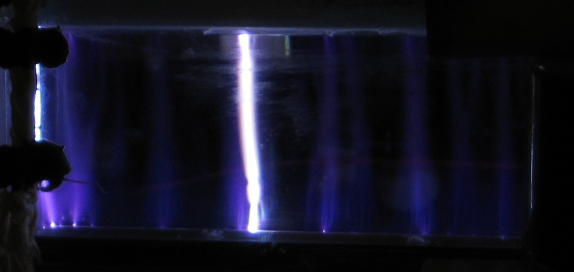
(04 June, 2006, early AM)
I managed (albeit with some difficulty) to connect
the 89-nf capacitor to the head, and I have started
to test. Operation is definitely improved. Here is
a photo of the discharge, and a photo of output on
a piece of white paper (which is bleached and thus
fluorescent):
The bright spots at top and bottom in the output photo
make it clear that most of the lasing is occurring right
near the electrodes. I will be thinking about ways to
change this so that operation is more even. (The first
thing I’m likely to try is adding some helium to
the gas mix.)
I must apologize for the awkward angles. I am now using
somewhat higher voltages, and I don’t have a
good place to put the camera.
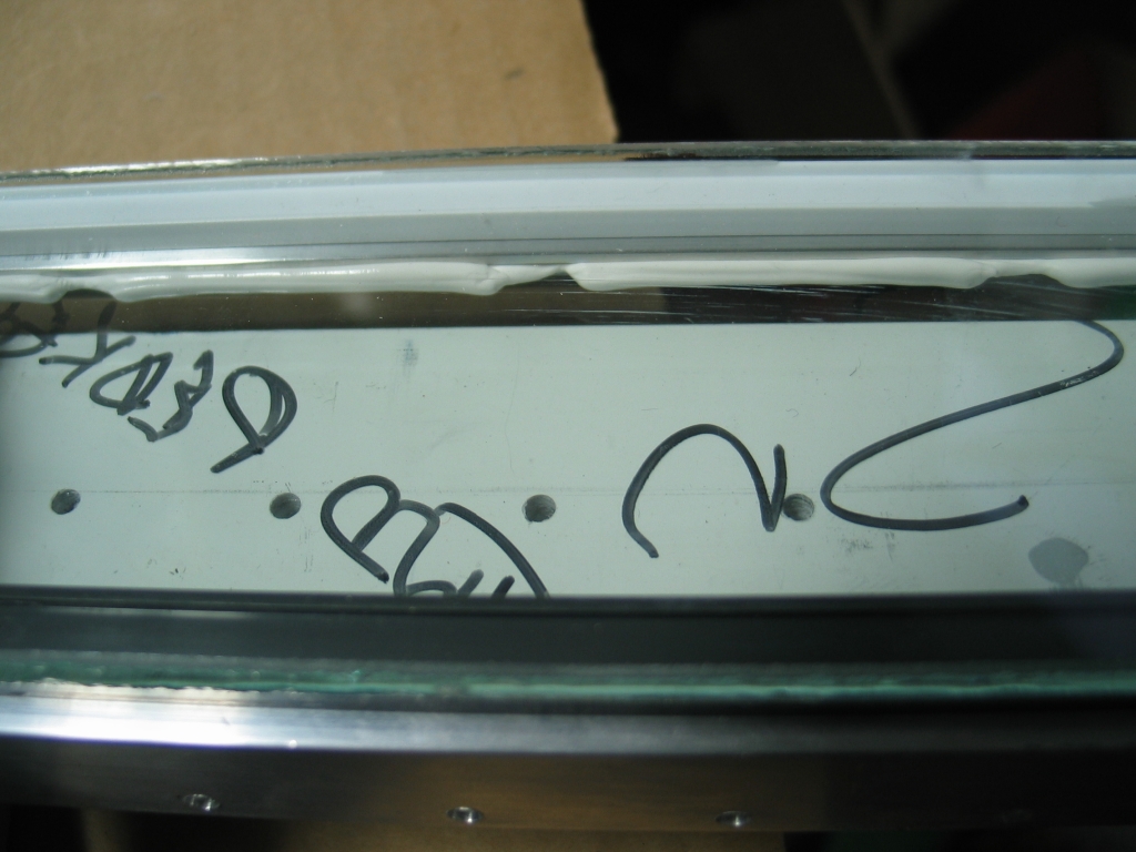
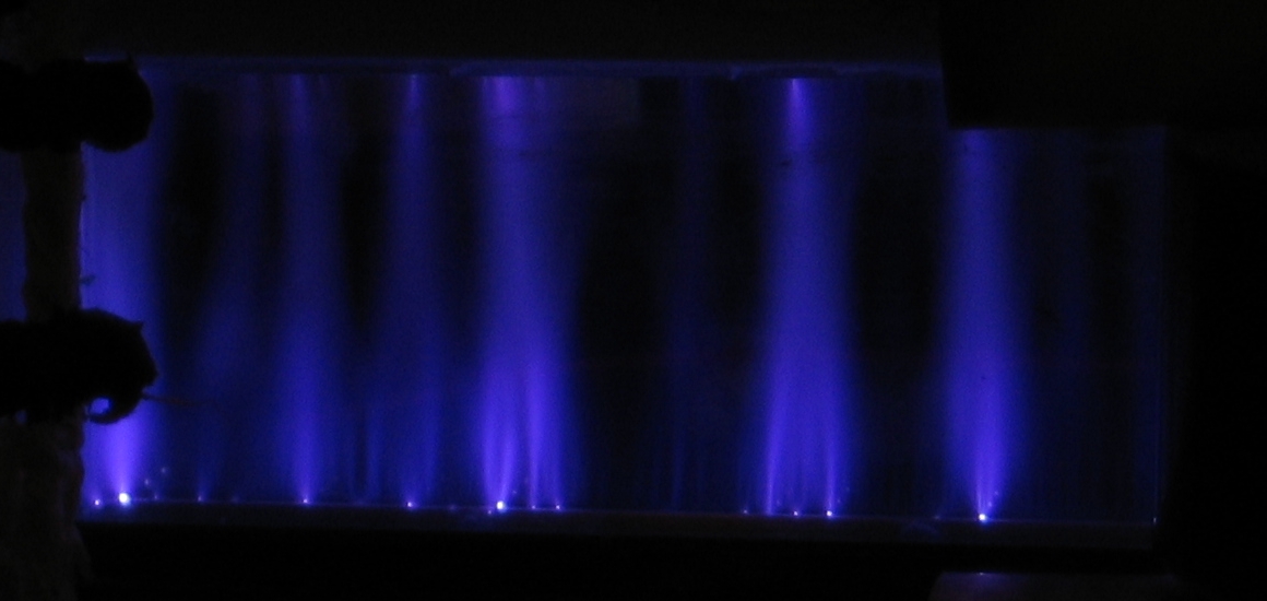
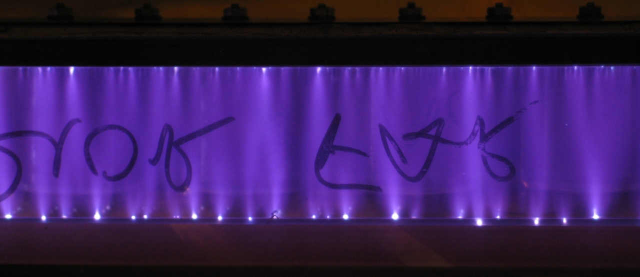
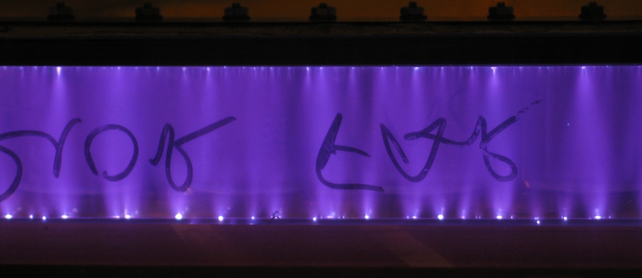
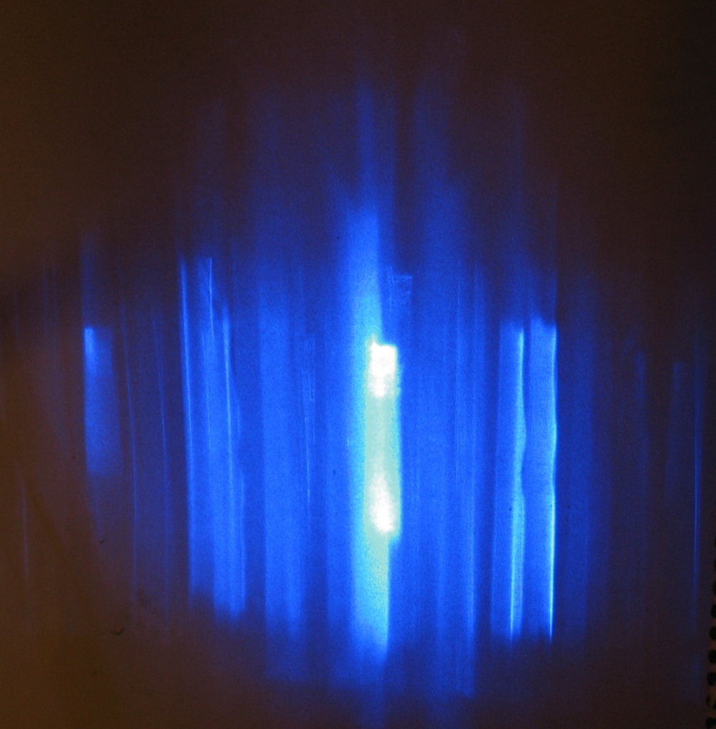
(04 June, 2006, mid-morning and late evening)
Here is a photo of the layout, two of the discharge
(as visible in a mirror; my apologies for the writing
on the glass, which I have not yet taken the time to
clean off), and four of output:
As you can see, the appearance of the discharge is now
closer to what I was expecting. (I should perhaps note
that the cathode is on the bottom.
Milan Karakas
tells me that the cathode typically shows larger and
brighter “hot spots” than the anode.) I
should also note that these output photos were taken
with the fluorescent screen considerably farther from
the end of the laser than the earlier one, which is part
of why they are so spread-out.
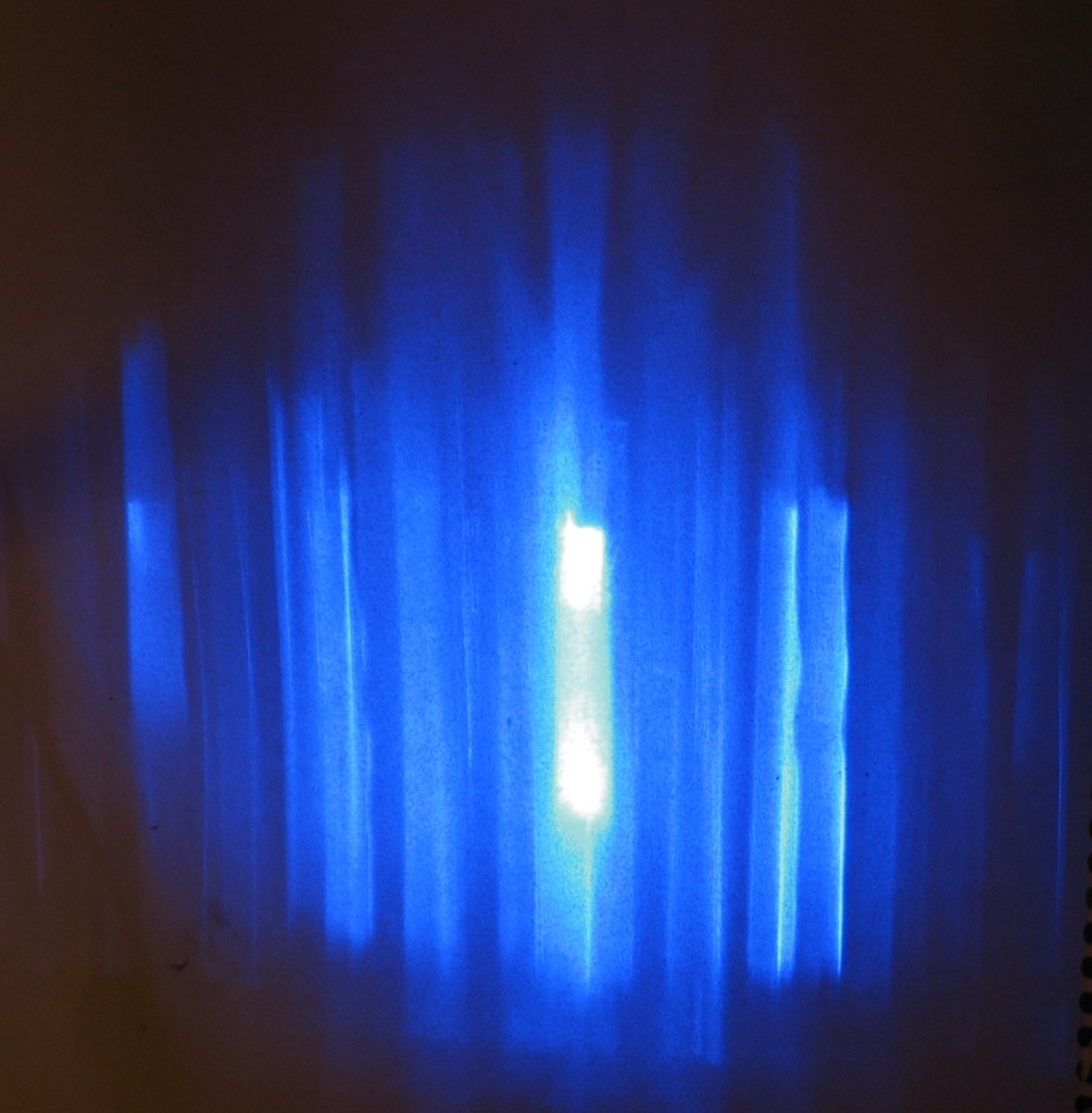
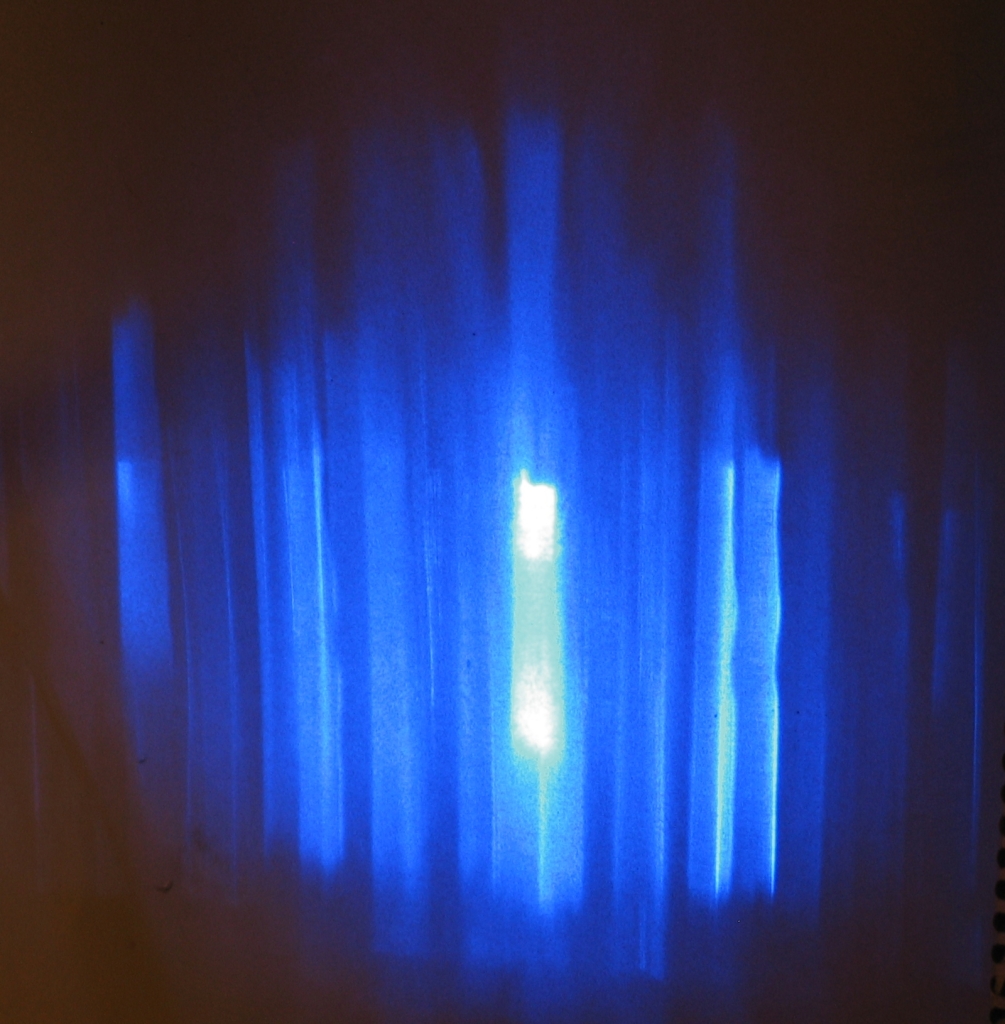
If you examine the four output photos, you may notice
some shadowy glow that overlaps the central bright areas
but is larger, and often slightly to one side. (Note the
differences between the 3rd and 4th photos.) When I
first observed this, I thought that I had twisted the
head in the process of attaching the new capacitor to
it; but Milan, who is extremely observant and has more
experience with this sort of discharge than I do, has
pointed out the fact that some of the hot spots on the
cathode are actually below the edge (this is particularly
evident at lower right in the first discharge photo),
which argues that part of the discharge may very well be
hugging the glass wall. That results in off-axis
amplification, which could easily be responsible for
some of what you can see in the output photos. There are
also, unfortunately, reflections from the walls, which
complicate things considerably and make it much more
difficult to interpret the photos.
There is, btw, no mirror on this laser yet. What you
are seeing is half of the output; the other half
emerges from the other end.
Next up: I will probably try to measure the pulsewidth.
(05 June, 2006, early AM)
I was just trying to get the trace on our Tektronix 7104
oscilloscope ...when my HV supply fried itself. This
project is now on hold until I either find another
supply that I can use, or repair the existing one. I
don’t know how many of the rectifiers are blown,
but the usual result is “all of them.”
(07 June, 2006, early AM)
I tested all of the rectifiers, and they tested good, so
I reassembled the power supply and tried the laser. It
runs, though I do notice that I have to turn the
autotransformer up higher to get it to fire. This may
indicate that something is wrong, but at least I can run
the laser. (I have bought 3 new rectifiers on eBay,
rated 80 kV each; 240 kV should be enough to sustain
30-35 kV output from the supply. You might think that 2X
or 3X the desired output voltage would do, but that
turns out not to be the case. It actually takes 8X to
12X, for reasons I may explain in a sidebar when I have
the time.)
Unfortunately, when I try to view the pulse on the
oscilloscope, all I can see is the electrical noise
generated by firing the laser. I think I’m
going to have to reflect the beam to a position
relatively far away, and possibly put the scope
behind a grounded screen. (There is already a screen
on the front of the photodetector; it doesn’t
seem to provide enough protection.)
(13 June, 2006)
I have installed the new rectifiers in the power supply,
and I have changed the output filter in an effort to
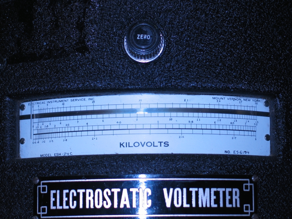
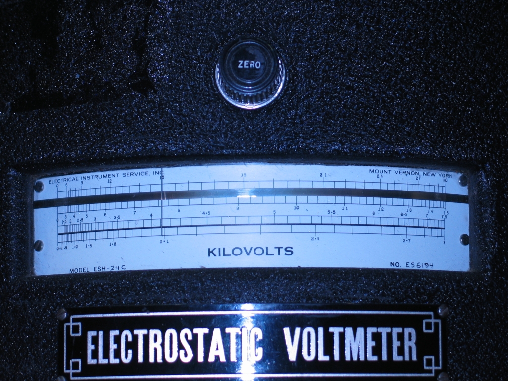
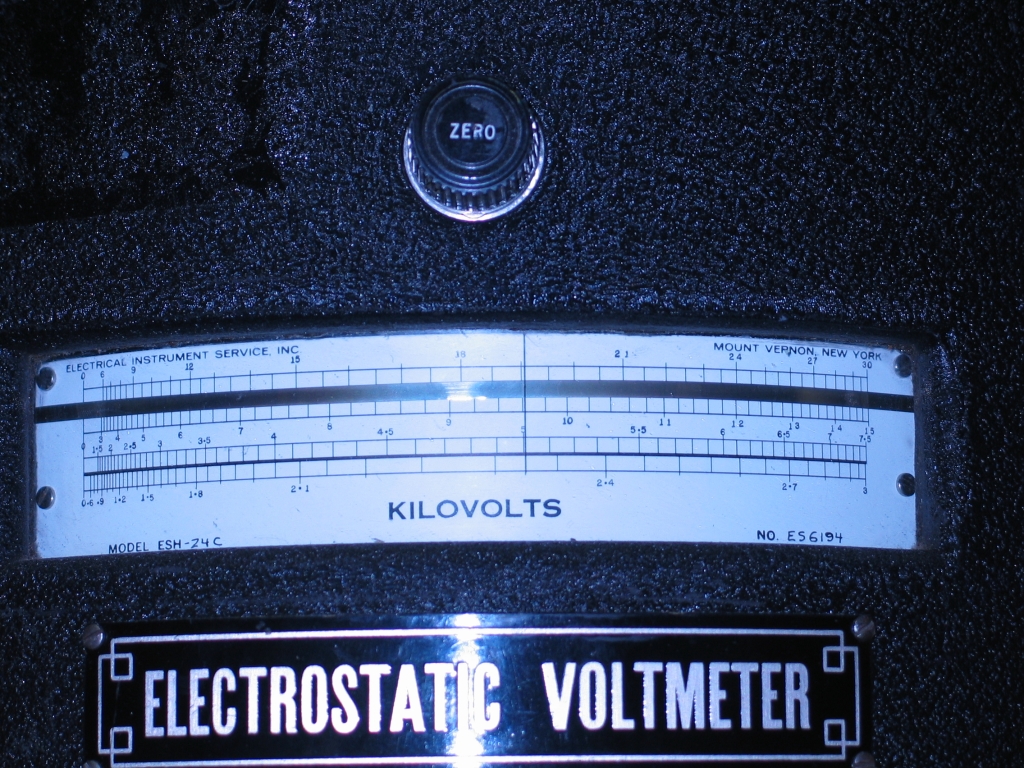
help protect them. I have also put a Sensitive Research
electrostatic voltmeter on the output. The voltmeter is
30 kV full scale, so I connected it to a voltage
divider: two resistors, each 100 megohms, in series,
with the meter attached between them. You would think
that this would be too much resistance, and would not
provide enough current to run the meter, but it turns
out that the input impedance of an electrostatic
voltmeter is about 1015 ohms (!), so it works
just fine.
Here is the voltmeter with the power supply at 0,
then at 75%, and finally turned all the way up:
Notice that the meter is registering just over 19 in the
photo on the right, which means that the supply was
delivering a little bit more than 38 kV, assuming that
the two resistors that make up the voltage divider have
equal value and that the meter is working correctly. At
this voltage the laser tends to self-flash, and also I
worry about X-rays, so I will be keeping the voltage
lower in actual operation, probably in the 30-32.5kV
range. Fortunately, with the autotransformer set to 75%
I get just about 30 kV out, as you can see in the middle
photo.
(06 July, 2006)
The irregularities I’ve observed in the operation
of this initial prototype head strongly suggest that
there is insufficient preionization. My current plans
call for either a new version of the head, or at least
the addition of a #8-32 threaded brass rod on top of the
cathode. This will provide a series of sharp ridges,
roughly 0.8 mm apart, which is about the optimal spacing
mentioned in at least one paper I’ve read. If that
still proves to be insufficient, I will add semiconductor
preionization on the inner face of the outer wall (that
is, the wall that is further from the peaker capacitors).
If I rebuild the head entirely, I will put peaker caps
on both sides. I don’t know how well that will
work, as I can only put a “dumper” cap and
spark gap on one side, but I think it’s worth a try.
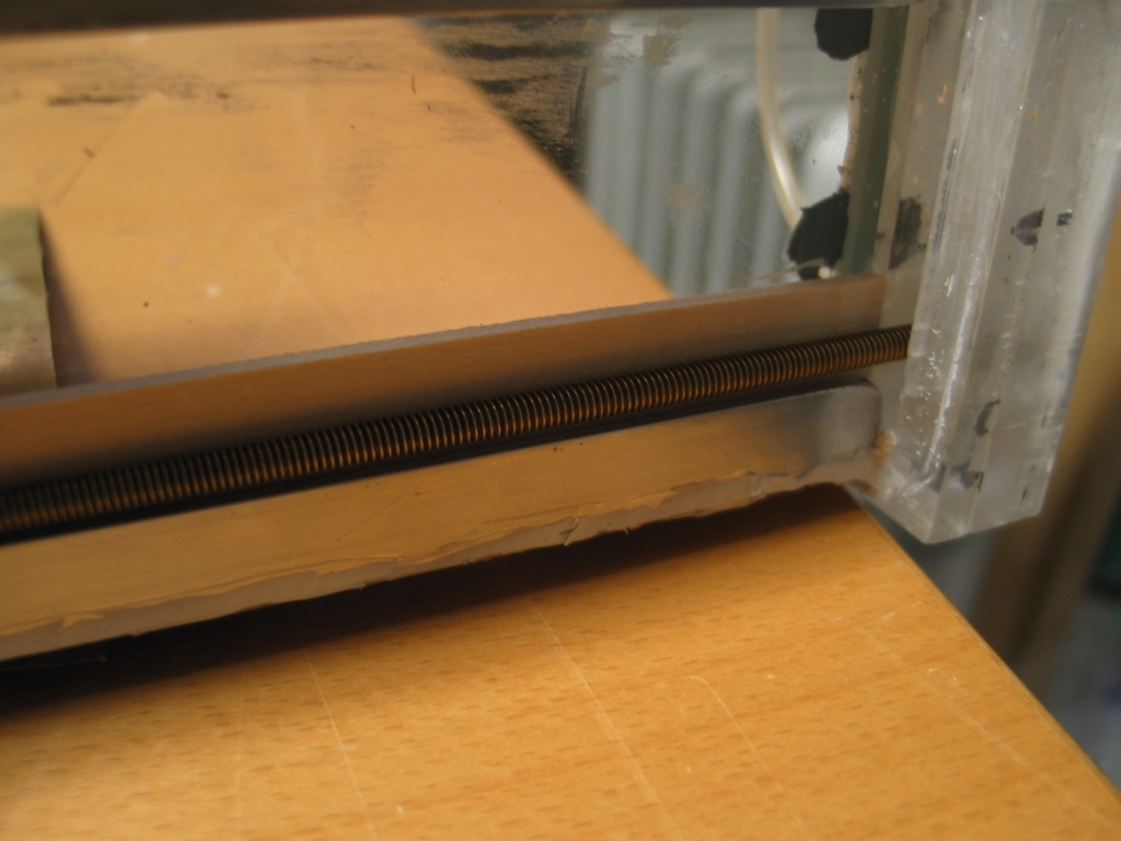
(10 August, 2006)
I ordered some threaded rod, which has now arrived, and
this afternoon I removed the outer wall from the laser.
I decided to make the threaded section longer than the
electrodes, and cut the rod accordingly:
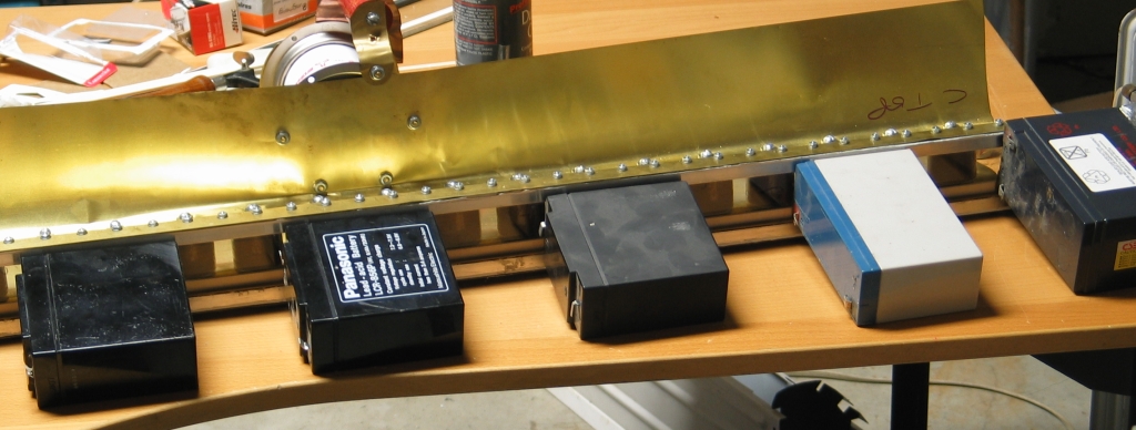
I then figured out how to hold it in place while the
silver-conductive epoxy that I’m using to attach
it to the original cathode is setting:
The batteries, which are lead-acid and quite dense, are
leaning on the threaded rod, which means that they hold
it down and also that they hold it against the shims,
which are 3/32" basswood, purchased at the local hobby
shop. They are probably not the precisely perfect
thickness, but they will certainly do for a prototype.
The rod was not very straight on its own, as you can see
from the middle photograph in the set of three (the end
is well up above the end of the aluminum extrusion, and
that’s not the only bend), and I wanted to be very
certain that it was pushed into the conductive epoxy, so
I needed multiple hold-downs.
The epoxy needs to set for 4 hours, after which I plan
to add dots of regular epoxy to increase the strength.
I also plan to have the glass shop make me two more bars
like the chamber walls, which I will apply to the outer
wall as stiffeners. (The silver epoxy has very little
mechanical strength, and I’m afraid that the head
could bend enough, when I pick it up, to break the
threaded rod loose if I don’t stiffen it somehow.)
Once all of that is in place and I glue the outer wall
back on, I will start testing for leaks. After the leaks
are eliminated, it will be time to run the laser again,
and I will provide pictures of what happens. May be good,
may not; I guess we’ll see, one way or the other.
(11 August, 2006)
I’ve been thinking about all those stray beams
that you can see in the photos of the output, and about
ways to minimize or eliminate them. They are of little
or no use, and they steal energy from the main beam.
They also make it difficult to align a mirror with the
discharge.
Seems to me that if I can effectively roughen the inner
surfaces of the walls so they are no longer such nice
mirrors at shallow angles, that may help; and I’m
thinking about ways to accomplish it.
What I really want is something “soft” and
dark, like flocking; but of course I can’t very
well flock the walls — I really don’t
want crap getting into my vacuum pump — and if I
put flat black paint on them I won’t be able to
see inside. Also, the discharge will eat the paint.
(Even if I shift from a mechanical vacuum pump to a
water-aspirator, so the pump could tolerate small solid
bits, the discharge would destroy any common flocking
material. I could probably flock the walls with something
extremely that isn’t sensitive to UV, but finding
such a material might not be easy, and flocking can be
a bit tricky, so if I can think of an easier way to deal
I will evade the issue.)
I have ready access to the inside face of the outer wall
right now, because it is lying on the table, and I suppose
that if I make it a preionizer by putting silicon carbide
on it, that will probably do; but if I do that, I will
have made two major changes instead of just one, and I
won’t know which one is having what effect, so I
am reluctant to go there. I almost think I should have
done the silicon carbide thing first, instead of the
threaded rod, but it’s too late for that now.
I’ve thought about simply smearing some angled
stripes of epoxy on the glass, as long as I’m
putting epoxy on the electrodes, but I figure the
discharge would just eat that, as well. Plasma is strong
medicine. OTOH, it could be worth a try even so. Hmmm:
perhaps I could mix some coarse sand into the epoxy...
that way, not only will the sand help spoil the
reflections, but the plasma will chew away only the
epoxy it can reach, leaving the sand grains sticking out
of the surface. It will take a ruddy long time for the
discharge to eat sand... I have some coarse sand in the
greenhouse, so this one will be child’s play to
implement, at least on the one wall — I’m
reluctant to mess with the other inner wall much, for
fear of getting crap on the electrodes. (If I build a
second head for this device, of course, I’ll have
plenty of opportunity to deal. OTOH, if I build another
head, there’s a good chance that I will be putting
SiC on the inner walls — the more preionization I
can get, the better ...unless, that is, I get superb
operation with just the threaded rod cathode.) Of
course, if I smear sand and epoxy all over the inner
face of the outer wall now, I won’t be able to put
carbide on it later, so maybe I will just wait a bit.
OTOH, if I don’t do anything now, I’ll
have to rip the head open again to do anything later. Argh.
[I’d ask your forgiveness for thinking out loud,
but for the fact that this is a development page; I am
perfectly happy to have my thought processes exposed
here. The final page about this laser, assuming it works
well enough to deserve a final page, will be considerably
more streamlined.]
One other thing that should help is to put a mirror at
one end of the laser. The stray beams, which are angled
off to the side, won’t get reflected back in, but
the main beam will, and it will get amplified in a
second pass through the machine. I haven’t even
tried to align a mirror with this cavity, partly because
I know what a pain it’s going to be, but I think
maybe we are getting close to the teeth-gritting point.
I have ordered stiffeners from the local glass and mirror
shop, the same place that made the sidewalls, and they
should be ready in a week. If there is any progress worth
reporting in the interim, I will put it here...
(12 August, 2006, early AM)
I checked the strength of the silver-loaded epoxy, and
was pleased to find it much better than I had expected.
Because of that, I decided not to wait for the stiffeners.
I added some J-B Weld™ epoxy to strengthen the joint
(somehow, I can’t quite imagine them putting this
use on their packaging as a testimonial), and I have put
the sidewall back on.
My logic for leaving the sidewall unmodified is that if
I find that the threaded rod is not enough I will need
to add more preionization, and the obvious way to do
that is to coat the inner face of the outer sidewall
with SiC, much as I did with my previous machine. (Link,
below, to “Doorknob DIY” laser.) If there
is already junk on the sidewall, I will have to acquire
a new one, which means a delay of a week. Better, I
think, to take it one step at a time. Now that I have
had the sidewall off, I think I can get it off and back
on again.
With any luck, I should be able to test the laser by
late this evening; the RTV (“Room-Temperature-Vulcanizing
Silicone Rubber”, commonly sold as bathtub caulk,
aquarium caulk, household glue, etc.) is still
soft now, and I don’t want to disturb it.
(later that same day)
I put the laser back on the bench, filled it with
helium, and tried it. There were various arcs along
the channel, and possibly a suggestion of a brighter
spark at the end where the helium was entering.
...So I satisfied myself that the RTV was reasonably
firm, and connected the vacuum pump to the outlet. This,
alas, got me just one huge bright pink arc at inlet port
end, every time I triggered the spark gap.
I’m not entirely sure where to go from here;
Schenck and Metcalf, when they built their original
laser, ended up putting a teflon cap over the teeth
of the bandsaw blade (their cathode) at each end of
the head, to prevent exactly this problem, so I may
just yank the outer sidewall again (argh) and paint
“corona dope” (insulating varnish intended
for use with high voltages) on the ends of the threaded
rod.
On the other hand, because I am not seeing discharge
at any other locations in the head when the vacuum
pump is running, I don’t really know whether
there are any leaks. (A discharge in plain helium is
very pink. Mix some nitrogen or air into it, and the
color changes significantly.) It is at least vaguely
possible that the inlet is the only place where the
helium is not diluted. On the third hand, I would not
expect that to prevent arcs and sparks from forming
elsewhere along the channel.
At this point, I need to think for a while. I may
just build a second head, and there is some chance
that I may move away from doorknob capacitors.
(late that afternoon)
For now, I have opened the head and painted insulating
varnish on the ends of the threaded rod. Whether this
will have the desired effect remains to be seen; I want
to let the varnish dry before I put the outer sidewall
back on, and then the RTV has to set before I can test.
Perhaps tomorrow evening...
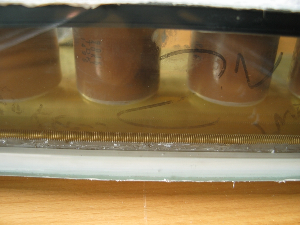
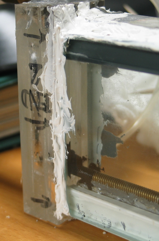
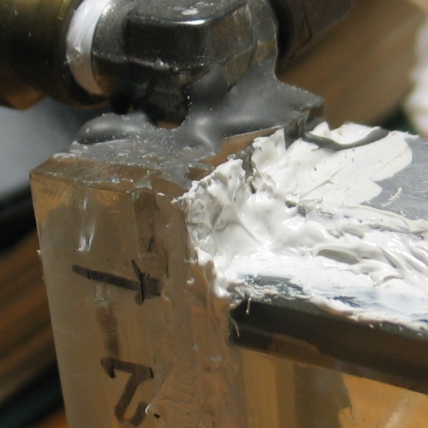
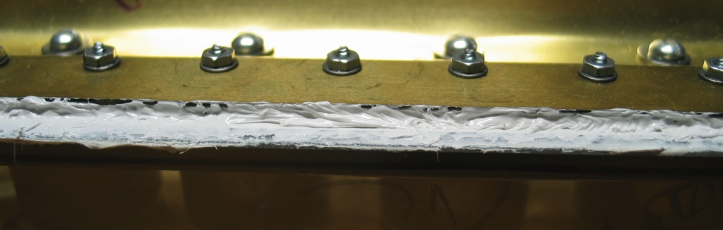
(13 August 2006, 10 AM)
Dismal failure. Not only does the head leak, but I
still get only a nice pink flashlamp at the inlet
end. It is time to reconsider. In the meanwhile,
here are some photos showing details of the head,
the new cathode, and some of the RTV seams...
I’m pretty sure the leaks are on the lower seam of
the sidewall, but as long as I can’t get anything
resembling a decent discharge I’m not sure that
there’s any point doing anything about them. Have
to think very carefully about this. There is one vague
possibility: I am fairly certain that the end of the new
cathode rod is very close to the silica window, and that
could encourage a surface discharge up the window to the
anode. I think I will take that endpiece off and chop a
cm or so off the end of the threaded rod.
(That afternoon...)
I took both endpieces off, sliced a cm or so off
each end of the threaded rod, and repainted both ends
with the HV insulating varnish. One end was a bit loose,
slightly detached from the aluminum extrusion, but I
didn't worry too much about it — I can always remove
the endcap again and smear more silver-epoxy on if it
appears to be an issue. (No, it wasn’t the end that
was sparking.)
I also found some of the leaks and put RTV on them; I
doubt that I got them all, but once the stuff has firmed
up I should be able to locate the rest. At that point I
go back to testing, and if it still just arcs at
the inlet end I expect that I’ll ditch this head,
because I probably won’t have a clue as to what
could be causing the issue.
(Late evening, 13 August, 2006)
So, I had an idea. What if the silver-epoxy isn’t
mixed correctly, and isn’t conductive? That would
certainly screw things up. My meter, however, tells me
that the epoxy is just fine. I supposed it’s just
as well — I would prefer not to have to redo that
entire thing.
(14 August, 2006)
A new day dawns. The laser is back on the bench, and
I removed extraneous stuff from the gas and vacuum lines,
which helped with the leak issue — turns out that
my vacuum gauge was on a leaky fitting. In tests, the
laser now arcs ferociously, but not at the end. (Finally!)
This tells me a thing or two:
First, it’s a bad idea to get the ends of the
electrodes too close to the windows.
Second, at least for this design in its current
configuration, a threaded rod does not seem to provide
sufficient preionization. (Sigh. We Had Hopes...)
Third, there’s a good chance that the spacing
between the electrodes is not uniform. (It always
arcs at about the same place.) I will be much more
careful about this parameter in the next head. There
is some chance that I simply can’t get the
pressure down low enough with the existing leaks,
and that if I clean the leaks up I will be able to
get a more even discharge. I may try that.
Fourth, while I can’t tell exactly where the
leaks are, I can certainly tell that they exist: as
I turn down the gas flow to reduce the pressure in
the laser, the sparks slowly change from pink to white.
While some of this could just be the pressure change,
I doubt that all of it is.
So.
The next obvious step is to provide some preionization.
I will have to decide on a method, though, before I do
any further rebuilding. Possibilities include:
How this works: as the voltage across the channel begins
to rise from zero, the little capacitors look like a
direct connection to the anode because they are uncharged.
The wire provides a good corona jumpoff point because it
is of small diameter. The resulting corona discharge
preionizes the laser channel and charges the little caps,
whereupon the main discharge takes over.
Advantage: Fairly easy to construct. In fact, if the
sidewall were thinner, all I’d have to do is put
a flat plate of brass shim stock on the outside
of the wall, and connect it to the anode. Unfortunately,
a full ¼" of glass is probably a bit much for that.
Disadvantages (minor): Have to get the wire stuck to the
wall, and it has to be straight. Not sure I have a
suitable wire — nichrome is nice, because it is
fairly strong when it is thin. (A thinner wire is a better
corona source.) [[This is easily taken care of: 75' of
#40 nichrome wire, .0031 inch diameter, was $3.99 on
eBay, with free shipping. It should arrive in a few days.
Now I have to figure out how to attach it to the glass...]]
How this works: even 1 mA of DC (takes a few kV) flowing
between a wire on the wall and the cathode, or between
two wires on opposing walls, will produce enough UV and
ions to preionize the channel. I will be using a single
wire if I do this, partly because I do not care to
rebuild my channel completely. It is crucially important
to be sure that the main discharge doesn’t jump to
the wire, however, for obvious reasons. My guess is that
if I supply the DC through a largish resistor, I probably
won’t have a problem, but We Shall See. (In the
worst case, of course, I can just disconnect the DC
supply and connect small capacitors from the anode to the
ends of the wire, as above.)
Disadvantage: requires a second power supply, which I
would have to build. Annoying. Still, it is remarkably
simple, and doesn’t steal any energy from the
main discharge.
...Meanwhile, on a slightly different topic:
I thought, when I was initially assembling this head,
that I had the electrodes rather straight and parallel.
I was wrong; after I got it built I looked down the
channel, and I could see minor wiggles. It is possible
that I introduced further problems when I added the
threaded rod.
Clearly, I want to avoid this sort of thing if and when
I build another head, so I have constructed a jig.
It’s based on a 4' ruler, aluminum, 2" wide and
1/8" thick, to the back side of which I have epoxied two
aluminum bars, also 4' long, 3/4" wide, 1/8" thick,
selected for straightness. I will photograph this when I
get a chance, but it’s rather plain.
It isn’t perfect, but it will probably do. As
long as the entire lengths of both electrodes are
pressed up against the jig, the result will be straight
and parallel to less than 1 mm over more than a meter.
Back on the regular track:
Following a suggestion made by Jarrod Kinsey, I used a
piece of ¼" polyethylene tubing as a stethoscope,
and even with the vacuum pump right next to me I had no
trouble detecting a minor leak in the upper seam of the
sidewall. I have plugged that one, and will use
Jarrod’s technique to check the lower seam when
the RTV has hardened. At that point, I may be able to
get a better vacuum, and perhaps I will even be able
to get a real discharge instead of just arcs and sparks.
(Done. Found one more leak, at one of the endcaps, and
plugged it. Should be able to pull a reasonable vacuum
tomorrow. Probably doesn’t make much difference,
as I expect to junk this head in any case, but maybe I
can learn a bit more from it before I let it go.)
(25 September, 2006)
I decided, after some thought, to work up
a different design, rather than proceeding with this
one. That design produced nearly 250 kW, and gave me
more confidence about preionization. It also reminded me
of the fact that even without a mirror this laser produced
significant output, so I am returning to it.
My first course is to remove the threaded rod, which
clearly did not improve things. If I can get the cathode
cleaned up enough, I will put a coating of carborundum
on the wall and reassemble the head for further testing.
If not, I will build a new head.
(29 September, 2006)
The laser does work, but it is clear that some damage
has occurred to the head. If I try to bring up the
pressure more than a very small amount, I get arcs at
the ends of the electrodes. Moreover, the fact that the
electrodes are not parallel annoys me. I have decided to
build a new head, and as long as I was going to do that
I also decided to build a new driver, with a
liquid-dielectric capacitor. That laser should, with
some luck, be able to deliver close to 1 MW, and I am
giving it
a page of its own.
(16 July, 2008)
I am still seriously thinking about rebuilding
this head, because it did some very interesting
things before it began to leak and spark. If and
when I get into that, I will definitely report
on it here.
(26 July, 2008)
It was clear that the electrodes of the previous
head were not straight. I am now thinking about
a change to the design that should hold them in
place more firmly, while allowing a good electrical
path to the preionizing coating on the glass wall:
instead of using plastic “H” beams,
I will use brass bar, 3/16" or 1/4" thick, and
probably 1/4" or 3/8" wide. It seems like a good
idea to epoxy the bar to the wall, and then
make the preionizer; once that structure is
complete, I can attach the electrodes to the bars.
For further information, please see
the second page for this laser.
Citations for some interesting papers about nitrogen and other lasers...
To the first page in this set, a general discussion
of the issues involved in designing and building a
high-performance nitrogen laser
To a page about my initial effort to produce a
high-performance nitrogen laser
To a page about my continuation of that effort,
which resulted in a laser that puts out about 100 kW and
can operate without a vacuum pump
To a “How-To” page about that laser
To the continuation of this page
To a page about my recent (starting mid-August, 2006)
redesign of the “DKDIY” laser,
which resulted in significantly enhanced performance
To a brief “How-To” page
about building the revised design
To a page about my current (late 2006) effort to build
a less-expensive laser with even better performance
To the Joss Research Institute Website
To my current research homepage
My email address is a@b.com, where a is my first name
(jon, only 3 letters, no “h”), and b is joss.
My phone number is +1 240 604 4495.
Last modified: Wed May 10 14:41:39 EDT 2017
Ongoing Calculations
Continuing Issues and Construction

Optimization begins
![]()
Continuing Work
Design of a New Head
References
This work was supported by
the Joss Research Institute
Contact Information: