Just about anyone who really wants to build a nitrogen laser of one sort or another can do so: it isn’t hard. Building a high-performance nitrogen laser, however, is a different story. (For the purposes of this discussion, I will establish arbitrary criteria for low-pressure nitrogen lasers, as follows: a low-performance nitrogen laser works, but cannot provide more than, say, 100 kW peak power. A mid-performance nitrogen laser puts out more than 100 kW but less than, say, 0.5 MW, or has poor pulse-to-pulse uniformity and cannot be depended on to put out at least 0.5 MW every time or nearly every time it is fired. A high-performance nitrogen laser routinely puts out well over half a megawatt.)
Please note that these criteria are for low-pressure nitrogen lasers. It is a relatively straightforward task to build a room-pressure nitrogen laser that puts out peak power in excess of 1 million watts, but such a laser need produce only a few hundred microjoules of energy because the pulse it creates is less than 1 billionth of a second long. As far as I am aware (as of early 2009), no Do-It-Yourselfer has yet managed to achieve the 1-MW level of performance in a low-pressure nitrogen laser, where the pulsewidth is typically 8 or 10 nsec and the required pulse energy is over 5 mJ.
My effort here is to work up a low-pressure design that a DIYer can reasonably expect to build, and that puts out at least a megawatt. My hope is that the laser I describe on this page will take us about halfway there.
It could be argued that because it uses a number of commercial high-tech components, this design is not sufficiently scratch-built. I would counter that in several ways. First, the parts and materials I used were readily available, so they should not present a bar to others who want to build a laser of this sort.
Second, it is possible to substitute homebrew parts for most of the commercial ones. I have, for example, already built a similar laser that used as its peaker a watercap made of two stainless steel trays I bought at a thrift store, instead of the laser-grade SrTiO3 “doorknob” capacitors that I am using here. I even built my own water-purification system for it. I used commercial deionizing resin for ease and simplicity, but double distillation is a viable alternative.
Third, I regard much of this project as a species of proof of principle; it is not a cookbook. If I can build a laser that puts out over a megawatt, you can do the same ...provided you are willing to put some time and effort into studying nitrogen lasers and the design and construction practices that are central to high performance. (I have provided a number of references at the end of the page on which I examine the Scientific American “Amateur Scientist” nitrogen laser article.)
This page provides a record of my own process, including the stumbles and false starts; the errors and the information I got from them; the little “Aha!” moments; the protocols and techniques that I have adopted; and so on. If I do succeed in building a high-performance nitrogen laser, knowing how I think and the criteria I used in making my design decisions may be helpful to you in your own efforts. In addition, I may have abandoned perfectly reasonable paths. You need to be aware of that, both on general principles and because I may not succeed with the paths I choose. Perhaps one or more of the others will prove to be better. (In fact, if you pursue one of those paths I would like to hear about it, regardless of how well it works or how massively it fails. My email address is at the bottom of the page.)
Let me stress once again the fact that this is not intended as a cookbook. It is not a set of steps that you can follow by rote. In fact, I would suggest that even if someone did provide a cookbook 1-MW nitrogen laser, it would be worth your while to understand it and even rethink it, rather than to follow the directions like a robot. You will learn a lot more, your experience will be a lot richer, ...and you will have a much better chance of debugging your laser and getting it to work. (These things almost never work right when they are first built, and debugging them can be tricky.) You will also have a better chance of improving the design and getting even more energy/power from it. Beyond that, developing an understanding of these principles will produce echoes in other things you do.
Finally, I must strongly suggest that even if you
don’t want to read the whole Megillah you should
at least check the warnings and suggestions, because it
begins to appear (as of the Ides of March, 2009) that my
initial choice of electrode material may be somewhat
suboptimal; most of this page follows that route, and
is somewhat misleading if you don’t attend to
the details.
(14 September, 2008, ff)
I have been thinking about a rebuild of this laser for some time now, and quietly amassing material to build it from. I already have some “doorknob” capacitors of appropriate value (900 pf at 40 kV), though they are currently installed in the original version of the head for this laser, and some pieces of glass that can serve as walls for the channel. As I probably mentioned on the previous page, the electrodes in the original version were slightly warped. I definitely want to avoid that in the rebuild; I will probably use 1/8"-thick steel spacers for stiffness (I have acquired four of these for the purpose), and I will probably epoxy the parts together instead of using silicone rubber, unless I can figure out a viable method that would let me disassemble the head for cleaning and/or tweaking. At the very least, I will epoxy the steel bars onto the glass, and I will epoxy the electrodes onto the steel bars on one side. That should provide a decent amount of stability even if I use silicone rubber on the other (preionizer) side so I can change it out if I want to.
I am also thinking very seriously about mounting the doorknob caps directly on one of the electrodes, and using brass shim that extends from the other electrode to connect to them. (The first version used shim stock from both electrodes, and had the doorknobs floating between them. It was painful to assemble.) I now have aluminum angle extrusions in two sizes, one of which may be wide enough to permit this. (When I have time and energy, I will try to create a diagram. Alternatively, I may just build the thing and take a photograph of it.)
In other respects, this head will be very similar to the previous one: glass sidewalls, SiC preionization (but see below, as I may be changing my mind about that), and aluminum electrodes; but at least one of the electrodes will be 1/16" thick this time instead of 1/8", and there will be other differences as mentioned above. I will probably drive it with 89 nF (again, as before), charged to perhaps 30 kV. That provides stored energy on the order of 40 J, which is quite ridiculous for a nitrogen laser, but there may be other projects for which I can use this head if it works well enough.
My early sense is that I will want to put the tin side of the glass on the outside of the head, because the tin oxide in the surface of the glass makes the surface very slightly conductive, particularly at high voltages, and that might possibly interfere with the preionizer. (For more information about this issue, and about figuring out which side is the tin side, please see “Continuing Issues and Construction” on the previous page.)
One other relevant issue: because I’ve been dealing with a small vacuum system while building a somewhat different type of laser, I now have a better gauge. This will help me detect and fix leaks, and will also give me a somewhat more precise sense of the pressure in the head and its relationship to the operation of this laser. Granted, the gauge may give inaccurate readings with helium; if I want to use a mixture of helium and nitrogen in this head I will probably attempt some sort of calibration to see how large the effect is. (I strongly suspect that there will be, but it’s always a good idea to check.)
(04 January, 2009, evening)
One of the first steps is to retrieve the capacitors from the previous version, which I have just done. I think I will also take the wall with the preionizer, so I won’t have to make a new one.
(some minutes later)
Well, that isn’t going to happen: the preionizer did not have a spark channel down it, and is probably too narrow for the new electrodes in any case. I also looked at the aluminum angle stock that I have on hand, and I suspect that I may once again have to float the doorknobs between two pieces of brass shim stock, as I did initially: if I use the widest extrusion I have to put the external edges quite far apart in order to get reasonable channel width (I’m planning on about 35 or 36 mm), and the inductance of the head would probably be too high for best operation. (If I had asymmetric angle, things would be easier.)
I am thinking about using 1/8" thick angle for the anode and 1/16" thick angle for the cathode, as that may improve the operation slightly and should be easy to construct. The slight wedge shape I’d get with one edge of the head thicker than the other is not a problem.
(Morning, 05 January, 2009)
I have rethought this yet again. If I do not use the widest angle, at least for the cathode, I will have the same assembly problems that I had last time. If I do use the widest angle, I will have to be careful with design and construction to keep the inductance down, but I begin to think that doing so is better than the alternative.
As of today, once I verify that everything can fit in the available space, I will start construction. If you think of the angle as a flat plate with things standing on it, here is what has to fit: the cathode (1/16" thick), the steel spacer (1/8" thick), the glass wall (1/4" thick), a small space so that the peaker caps are not touching the wall (perhaps 1/16", and certainly no more than 1/8"), and the peaker caps themselves (more than half of their diameter, because there must be room for all or nearly all of the termination diameter in order to get good conductivity and in order to minimize the inductance of the connections).
If it does not all fit I am free to return to the slightly smaller angle, and to figure out how to deal with the issues I had last time. One possible alternative: I could use a flat extrusion for the cathode instead of an angle, so that the capacitors would be standing up at the left side in the diagram you see below, rather than hanging over the glass wall, and I could minimize the inductance by running the brass shim close to the glass wall on its way across between the capacitors and the anode rail. Here is an initial diagram, using angle extrusions at both sides:
Notes: The aluminum (pale gray) is 1/16" thick; the steel (darker gray) is 1/8" thick and 1/2" wide; the glass walls are 1/4" thick and 3" wide. I have a jig, constructed some time ago, that I can use to position the extrusions so that the channel is the correct width.
(That evening...)
In thinking further about this, I realized that if I use a broad flat extrusion as the anode I can mount the caps on it and shape the brass shim so as to minimize the inductance. I hope that will work passably well. Here’s a drawing:
Notes:
There is a small happy thing about using a ruler: it is simple to find and mark the places where the capacitors will be attached.
I will, when I have time, redraw the diagram to show the outline of the peaker cap and the shim.
(Evening, 06 January, 2009)
I have epoxied two steel rails onto one of the pieces of glass. It was a bit difficult to apply the epoxy, and my work is somewhat uneven, but I think the steel is firmly in position, and I don’t think there will be any places between the steel and the glass where air will leak in. Once the epoxy has set, I will epoxy the other two rails onto the other piece of glass. (As mentioned above, the face of the glass that is “contaminated” with tin is on the outside of the head.)
I also acquired some pieces of thin brass to shim the angle that serves as the cathode, which (as you can tell from the diagram) is thinner. Unfortunately, what they had at the hobby shop was in strips only 1 foot long, so 4 of them will be required for each face of the thinner extrusion. Also, they had only 5 pieces that were .032" thick, so I got 4 of those and 4 that are .025" thick. (Any inequality in the positioning that results from the difference will be so tiny that it shouldn’t be a problem.)
(Evening, 07 January, 2009)
I had some time to think this over yet again today, and it occurred to me that I could probably get lower inductance (and eliminate the positioning shims) by doing it this way:
A you can see, I have also decided, tentatively, to use a channel width of perhaps 28 or 30 mm rather than the 36 mm I was (equally tentatively) planning on earlier. In the meanwhile, I have epoxied the other two steel rails to the second glass wall.
This is about the point at which I usually start to
become afraid that I’ve made some howling
horrendous error in my understanding of something, and I
generally take a short break before I grit my teeth and
continue with construction...
(Early AM, 07 January, 2009)
(Caution: excessive handwaving follows.)
I have an old 89-nf Maxwell capacitor, which I will probably use as the main store for this laser. As I note, above, it will hold about 40 J at 30 kV. If I ignore the impedance of the driving circuit and guess at the inductance (let’s try 100 nh), I get a probable pulsewidth of about 300 nsec, which is likely to be reasonably close to reality. If I pretend that the pulse is a half-cycle of a sine wave, the peak power is probably about 175 MWE. If I now assume that peak power is reached when the voltage has fallen to perhaps 2/3 of its initial value, the current from the main store should max out at about 9500 Amps. This is well within the capability of a GP-70 spark gap, but I don’t think the GP-70 will handle 30 kV in air, and I do want to be able to charge the cap to that voltage. (The maximum rated voltage for these gaps can be reached only when the device is immersed in oil or some other insulating medium.) Sigh. I will probably end up using either a GP-15B or a GP-32B, either of which should handle at least 36 kV in air.
You can certainly build your own spark gap if you want or need to. Try to keep the electrodes wide if you can, and with a fairly shallow surface curve, so as to keep the inductance down. There is some information about triggered gaps on the Web, and you probably want to read it. (You probably don’t want to use a free-running gap in this type of application, because it doesn’t let you control the charging voltage or the times when the laser fires.)
The Avco-Everett C5000, which has a channel about 60 mm across, appears to get best output (with a 20 kV power supply) when I run it at perhaps 15 Torr. If we presume that the published value of 100V/T*cm is about right, then 6 (cm) * 15 (T) * 100 suggests that the maximum voltage on the peaker caps during a firing cycle is about 9 kV. If I take that number and transfer it to this laser, a channel width of 30 mm should provide best operation at about 30 Torr. That seems quite reasonable, provided I can obtain sufficient preionization to get a clean and stable discharge at that pressure.
Note that the voltage I expect the circuit to attain at
peak electrical power is quite a bit higher than the
voltage I expect to be able to achieve on the peaker
caps during lasing. That’s because the discharge
cycle is far longer than the total time between the
beginning of conduction in the spark gap and the end of
the laser pulse. This is one of the reasons why nitrogen
lasers are so terribly inefficient: even though it
typically takes many nsec before the laser reaches
threshold, it takes a lot more nsec to discharge the
capacitors, so most of the stored energy is wasted.
Alfonso Torres Rodríguez
tells me that he has tried circuit topologies that are
essentially the ones shown here on the left (“Option
1”) and right (“Option 2”), and that
he gets better results with Option 2 (spark gap to the
ground side of the peakers from the main store). Neither
of us is sure why this should be, but he has observed it
with more than one of his lasers.
Note that in Option 2, the anode of the laser is
connected to the negative side of the power supply.
This is slightly counterintuitive, but you will notice
that the bleed resistor effectively goes from the
negative side of the power supply to the negative side
of the main store, which is [appropriately] connected to
the cathode of the laser. When you trigger the spark
gap, the anode fairly abruptly becomes strongly
positive.
Alfon uses an inductor in his lasers, rather than the
bleed resistor I show in these schematics (which is
actually both a charge and bleed resistor in Option 2),
but that shouldn’t have a significant effect
during the discharge cycle.
I may try both topologies with this laser, to find out
whether I observe a similar effect.
(29 January, 2009)
Last night it occurred to me that it would be
quite easy to run this head as a voltage-doubler
circuit laser. Instead of using a dumper capacitor
and putting doorknobs on one of the electrodes,
I could put [smaller] doorknobs on both electrodes,
with a sheet of brass shim stock between the two
sides as the common, and with a spark gap across
one of the sets. I actually have some 1.4 nf 20 kV
doorknobs that would probably work, and I am
tempted to try it as an alternative. It does not
require any modification of the head design, so
it could give me a moderately close comparison of
CT and doubler performance, though not precisely
direct because of the differences in the capacitors
and the operating voltage. Still, a matter of some
interest.
(End of interlude...)
(08 January, 2009)
Here is a quick mockup of the channel cross-section
on the bench; cathode on the left, anode on the right:
It looks like things will just about fit — the
terminal at the left side of the doorknob is just barely
covered by the aluminum, and if I raise the doorknob up
off the glass it won’t be completely covered. There
will be a sheet of brass shim stock under it, though, and
I suspect that this will be viable. Both angles appear to
be slightly different from 90°, but the one on the
right is noncrucial, and the one on the left is not very
far off.
Next steps:
At about that point it should become possible to test
the laser, assuming that no new leaks have been created
during the final assembly.
(09 January, 2009, evening)
I just marked and drilled the holes for the caps and the
shims, noting in the process that both of the angles are
slightly warped. If I were to glue them in place as is,
the channel would be something like 2 mm wider in the
center than at the ends. This is annoying, but only
mildly so — it probably wouldn’t seriously
interfere with the operation of the laser, and I intend
to hold the extrusions in place against a forming jig
when I do the gluing, so it won’t be an issue.
(Side note: I could have staggered the shim holes,
rather than putting them directly opposite the caps,
but I doubt that it would make a huge difference, so
I didn’t bother.)
You can’t see it in these photos, but the bench
that the mockup is sitting on is also warped; if I were
to do the assembly there, the middle of the laser
channel would be about 2 mm lower than the ends, which
is more than slightly annoying, and would
seriously interfere with the operation of the device. I
must find a better surface on which to do my gluing.
(I would stiffen the upper wall, but there isn’t
really any room for stiffeners. I may, however, be able
to stiffen the lower wall.)
There are several degrees of freedom involved here...
(Evening, 11 January, 2009)
Can I decompose this tangle a bit? I suspect that I
can. For one thing, the fact that the bench droops is
probably a non-issue, as I can easily make a jig to hold
the completed head at a large number of points and
maintain its flatness along its length. True, it would
be nice if I didn’t have to; but even if I do my
gluing on a flat surface there is a good chance that
various forces involved in later assembly will warp it,
and it is good to know that I can compensate for some
of this particular form of distortion. (See below for
further progress.)
The next large issue is the set of items that I will
subsume under the term “parallelism”. The
active edges of the extrusions should face directly
toward each other, and the channel width should be
uniform. I tried, earlier today, to find a straightedge
at least 3 feet long and 28 or 30 mm across. This
attempt was not successful. I had trouble finding
anything at least 3 feet long that was less than
32 mm across, and many of them were even wider.
This leaves me with a few choices. I can take something
that is too wide, and cut one edge off it; but I would
have to straighten the cut edge, and I don’t
currently have acces to the equipment to do that. I can
take several things that are too short and too narrow,
and find a way to combine them. This is expensive, but
could actually be viable, as I have a straightedge that
I can use for alignment purposes; but setting up one
edge of a build is not the same as setting up two, and I
do not like the idea much. I can glue one electrode into
place, using a straightedge to keep it correctly shaped.
Then I can find or build a moderately soft spacer that
is the right width, and use gentle pressure to hold the
other electrode and the spacer against the first
electrode, which now serves as a straightedge. There is
some loss of fidelity, but if I do this well, the loss
will be minimal. The problem with this method is that it
makes it harder to be sure that the edges face each
other directly.
One more possibility: acquire two pieces of moderately
soft material (e.g., wood, or possibly thin
aluminum extrusion) that have uniform width and are not
too badly warped, and glue them together against a
straightedge to shape them and with a backing plate for
added stiffness. The backing plate will probably have to
be segmented (if it had been available as a single
piece, I probably would have found it this afternoon),
but my guess is that this will make relatively little
difference. Worst case, the spacers themselves may have
to be segmented, which is somewhat more worrisome, but I
think we will cross that quicksand only when it
liquefies under us. I think this is the best option that
I’ve come up with so far, and I think I will adopt
it.
That leaves twist, which should be minimal if I am
at all careful, so I think I will ignore it unless
there is actually enough of it to be significant.
(Early AM, 12 January, 2009)
I just went looking through my materials, and found that
I had already constructed a 4 foot wooden bar that is 30
mm wide, fairly straight, and reasonably flexible. It
might work without a backing plate, but I expect to use
one anyway so I can glue both electrodes into place at
the same time. I was hoping for something 28 mm wide,
but 30 isn’t bad. The real problem is that this
bar is about 3/16" thick, and that’s too big
— it would just barely fit into the head without a
backing plate, if the glue joints are thick enough. With
a backing plate, it just won’t go. Either I must
devise a workaround, or I get to make another bar out of
thinner material.
(Afternoon, 12 January, 2009)
I went to the hobby shop, to try to find some suitable
materials. This was not very productive, so I went to
the hardware store. The selection was sparse, and for
the most part unsatisfying, but they did have one item
that I think I can use. It is a strip of zinc-plated
steel 1/8" thick, 4 feet long, and 1¼" (31.75 mm)
wide. I was seriously hoping for thinner strips, so I
could make a narrower separator, but that wasn’t
going to happen. On the other hand,
MSC Industrial Supply
carries 1/8" steel bar that is 1.13" wide, in 6 foot
lengths. I may grit my teeth and order one of these, as
the price is not too horrendous. That would leave me
the strip I got today as a backup, or for another head
that needs wider channel spacing.
(Midnight that night)
I did, indeed, order the bar from MSC, and we’ll
see what I can manage to do with it when it arrives. In
the meanwhile, I must clean up the corners and edges of
the electrodes.
(Afternoon, 13 January, 2009)
The steel strip has arrived (MSC is incredibly speedy).
I have cleaned up the corners of the electrodes, and
buffed the active edges with steel wool.
Protocol note: My usual method is to file the
corner into a smoothly rounded curve, taking care to
round and smooth the edges in the process; then I use
extremely fine sandpaper to remove the marks left by the
file. When I am satisfied with the general shape I rub
the corners and all of the active electrode edges rather
firmly with extremely fine steel wool. This removes much
of the oxide coating that forms on aluminum (though not
all: an extremely thin coating reforms in a few
seconds), and it reduces or eliminates minor burrs and
scarring. It can’t remove large nicks and burrs,
but I try to avoid using badly scarred edges as
electrode edges in any case. In the event that a piece
of extrusion has no reasonably clean edges, either it
should be replaced, or a bit of extremely
cautious filing and sandpapering is probably
indicated. As to the corner shape, in the past I have
usually tried for something vaguely approximating one of
the formal profiles that provide fairly smooth
transitions in the electric field. This time I contented
myself with just rounding and smoothing them, in the
hope that under the conditions I can expect here it
won’t make all that much difference.
(A bit later that afternoon)
I have cleaned the grease and rust off the strip, and
soon I will get to epoxy the electrodes to the upper
wall; but first I have to figure out how to clamp them
in place without distorting them. Fortunately, it
won’t take much pressure from the clamps to take
out the warpage. Unfortunately, if you think of the
cross-section as an “L”, any pressure that
is applied to the vertical stem instead of the baseline
is bad, so a wee bit of creativity is indicated. In
fact, this issue may make it difficult for me to use the
outside face of the other glass wall as the base for my
gluing operation, and I am thinking about possible
alternatives.
(Afternoon, 14 January, 2009)
Rather than leaving the bench in its drooping condition,
I propped up the middle with a plank so that the top was
more or less flat as viewed by eye. (So much for the
swayback issue.) Then I took two carpenters’
clamps and used them to hold a previously-built channel
spacer on top of a wooden strip, just at the front edge
of the bench. This early channel spacer was constructed
on an aluminum ruler, so it serves as a straightedge.
With that at the front of the bench, I positioned the
far wall of the head (the one that will become the
preionizer) just behind it, with the glass facing up and
the steel bars facing down, and set the channel spacer
on top of that. Then I put another piece of wood and a
second aluminum ruler behind the glass wall, and set the
electrode extrusions in place, using some old
sealed-cell lead-acid batteries as weights to hold the
back straightedge in place:
Then I mixed some slow-setting epoxy (so I’d have
some time if I needed to tweak the position after I put
the “lid” in place), applied it to the steel
bars on the upper wall, and carefully set the upper wall
on top of the electrodes. Because the bench is not level
it promptly slid out of position, and I was obliged to
generate some impromptu spacers to hold it in place.
Here is a detail of one of the ends:
The steel strip is not as straight as I might like, but
most of the problem is at one end, which I have avoided.
You can see it extending from the setup toward the lower
right in this detail.
It will take a while for the epoxy to cure, after which
I will endeavor to create the preionizer on the inside
face of what is, just at the moment, the lower wall. I
think I have a viable thought about end-fitting design,
and with some luck it won’t be too terribly long
before I can start checking for vacuum leaks.
(Early AM, 15 January, 2009)
I just checked the leftover epoxy in the mixing container,
and it was still not hard. I seriously hope the stuff
hasn’t aged out. I will check it again after I
sleep; fingers crossed.
(Early PM, 15 January, 2009)
The epoxy is now significantly harder than it was,
and I think there’s a good chance that it will
cure fully, but it is not yet firm, and I cannot take
the setup apart until it is. This means that I
can’t build the preionizer yet, because that
piece of glass is under the one with the epoxy.
I can, though, build the end fittings, and I am
working through some design notions. (I have added
a section, below, about this.)
(Early AM, 17 January, 2009)
It is perhaps a good thing that construction of the
preionizer has been slightly delayed: turns out that one
of my favorite pottery supply places carries 325-mesh
silicon carbide, and is having a bit of a New Year
sale. I have been making preionizers with 100-mesh SiC,
which seemed to work fairly well, but I tested with some
coarser material and found that it was not as good, so I
will be pleased to try a finer grade.
(Early evening, 18 January, 2009)
The channel looks fairly straight, and I’m pleased
about that. I may, however, have missed a trick: when I
originally glued the steel rails to the glass walls, the
bench was swaybacked, and the glass wall kept that
shape. Perhaps I should have put at least some weight at
the ends of the glass when I glued the extrusions into
place, to straighten it. I didn’t, and you can see
some of the resulting gaps in the epoxy in the photo on
the right. On the other hand, if I had weighted the wall
down, it would now be pulling up on the extrusions, so
maybe it is just as well that I let it hold its shape.
This is annoying, as I will have to fill in the gaps
before the head will hold vacuum, but my hope is that it
will not otherwise be a problem.
(Early AM, 19 January, 2009)
Fixed: I mixed more epoxy and filled the visible gaps.
(Note, added that evening: the epoxy appears to be curing
nicely.) I don’t yet know whether there are other
places that will leak when I apply vacuum, but I suspect
that there are: whenever you construct something of this
sort, the chances are that it will leak; the problem is
not finding out if, but rather finding out
where.
(More as it transpires.)
(Early AM, 15 January, 2009)
My initial thought about this is to use the brass strips
I acquired earlier to eliminate the dead space where
preionization is neither necessary nor helpful. If I
glue these to the glass just inboard of the steel bars,
and make sure there is a good conductive path to them,
they can easily conduct the HV to the edge of the active
preionization area, which would then be only about as
wide as the channel itself.
Making sure that there is a good conductive path to the
brass strips from the electrodes, however, will not be
trivial. I want to have this wall be demountable, in
case I find that I want or need to swap out the
preionizer, and this probably means that the adhesive I
will use to attach the preionizer wall to the electrodes
is going to be silicone rubber aquarium caulk, which is
not conductive. The result is a nontrivial problem, and
I am thinking about ways to deal with it. One
possibility is to find some conductive mesh or felt, and
place it between the electrodes and the brass strips.
The preionizer probably takes only moderate power, so
the mesh, if that’s what I end up using, is
unlikely to suffer much damage during repeated
discharges. I think I like this approach, at least as an
initial thought, but I would have to find or buy some
mesh or metal felt, so I am continuing to think about
other possibilities.
(Evening, 19 January, 2009)
I recently suggested corona-wire preionization to Alfon
(Alfonso Torres Rodríguez) for his nitrogen
laser, and he has had rather encouraging results with
it. I may change my mind and try that as an initial
method for this laser, because it is a lot easier to
implement than a semiconductor field with a gap in it.
Moreover, if I decide that the wire is not working well
for this design, I can take the wall off and rebuild it
very easily in the other format. Corona preionization of
that sort has two other advantages: first, it can be
turned on or off, so it should be easy to tell whether
(and to what extent) it is changing the performance.
Second, it can be done actively (with a small source of
HVDC) or passively (with small capacitors). This makes
it very attractive, as it offers a nice easy way to get
rather a lot of information. The more I think about
this, the more I like the idea.
(AM, 20 January, 2009: Inauguration Day)
In the course of thinking about this, I have decided to
put a wire on each glass wall, which gives me even more
flexibility. I have some 8-mil nichrome wire, which
should be good for this purpose. I also have a 7.3 kV
oil burner transformer, and although it is single-ended
I should be able to make a bipolar power supply from it...
...though I will probably have to use two or three 15 kV
diodes in series for each polarity. (I have shown two in
the diagram.) If you find that puzzling, do the numbers:
7.3 kV RMS, x1.4 for peak voltage = 10.2; double it for
the fact that in an AC circuit the voltage has both
polarities, and you are at 20.4 kV, already more than
one 15 kV diode can handle. You want to double this
again, for a total of ~40 kV PIV, to provide a minimal
safety factor. My general stance on this issue is that
if you use rectifiers with PIV rating of at least 8X the
RMS voltage, and if you provide chokes to help prevent
EMP generated by the discharge system from propagating
back to the power supply, you will rarely have trouble.
My one worry here is equalizing the voltages across all
of the diodes, but I have some 100-Megohm high voltage
resistors, and I can use those in a divider-/-equalizer
chain, as I have shown in the diagram above.
(“-WMWM-” indicates a 100 M resistor.)
Alternatively, I also have a 10 kV oil-burner
transformer with a secondary that has a grounded
centertap (just like a NST), and I can get one polarity
from each end of the secondary if I don’t mind
slightly lower voltage. That also relaxes the PIV
requirement a bit, though with 15 kV diodes there is no
functional difference.
The Rebhan group
(citation on my page about the Scientific American
design) used a very large series resistance on their
preionization supply, 400 Megohms in series with the
“hot” lead to the [single] preionization
wire, and another 400 Megohms in series with the
connection to the cathode of their laser. I think I will
use considerably more current in this implementation.
(If that much current doesn’t seem to work well, I
can always add resistance to decrease it.) I should have
about twice the voltage they had (they used a single 7
kV supply, according to their diagram), and I think 100
M or even 50 M in series with each of the connections
should be a good starting point. I am also thinking
about trying AC, to see whether that works. (It
certainly simplifies the construction of the corona
supply!) If the shot-to-shot uniformity is lousy, though,
I will go to DC.
Additional points about the Rebhan laser: it used
astonishingly large capacitors, with the main store (as
large as 150 nF) charged to 35 kV, and it produced up to
30 mJ output energy (with 10% SF6 in the
nitrogen), in pulses that were up to 19 nsec long. In
other words it was one of the largest and most energetic
nitrogen lasers ever built, though not quite one of the
most powerful. (Several published nitrogen lasers have
produced at least 3 MW peak power.)
The authors found that they could get good performance
with rounded electrode profiles if they did not add
SF6; but that they got better results with a
grooved cathode, and they found that this was necessary
for decent pulse-to-pulse uniformity when SF6
was present. I am using rounded profiles here, which
should be satisfactory with plain nitrogen. They also
found that copper was the best electrode material in
their design. Stainless steel produced equivalent
performance with plain nitrogen, but reacted with sulfur
hexafluoride. They also did not do well with aluminum,
and unfortunately their phrasing is slightly ambiguous.
(“...because the pulse duration is relatively
short and the peak energy amounts to 9 mJ with an
admixture of SF6.” — Does this say
that the pulse duration with aluminum electrodes was
short only with sulfur hexafluoride in the gas, or
always?) I have had decent performance with aluminum
electrodes in my previous lasers, and I hope this one
will also work well.
In addition, they had to provide almost 7" of unexcited
electrode length at each end of their laser in order to
avoid sparking and degradation of the performance. I
have allowed only about half that much distance in this
design (the last peaker at each end is 4.5" from the end
of the electrode, but I think it is safe to think of a
zone of excitation at least 2" across for each of the
doorknobs); I can increase it to 5.5" by removing one
peaker cap at each end, if that proves to be necessary.
(3 AM, 21 January, 2009)
I have applied the first preionization wire to the
“far” wall (that is, the one that is not
yet attached to the electrodes), using a dot of epoxy
at each end and a dot about every 2" along the glass.
Once the epoxy cures, I will do the same with the
other wire. I have positioned this wire 2/5 of the
way across from one steel rail to the other, which
puts it closer to the cathode than to the anode. I
expect to position the other one the same way.
(10 PM, 21 January, 2009)
I have applied the second preionization wire, situating
it 8 mm out from the cathode toward the anode. The epoxy
is curing.
(10 PM, 22 January, 2009)
The main part of the head is now assembled. Here are
some photos.
(4 AM, 23 January, 2009)
I believe I have figured out a good way to hold the ends
of the wires and make connections to them: flat-head
machine screw, epoxied (head down) to the glass wall;
on the screw are: a nut, a washer, the end of the wire,
another washer, a second nut; a washer, the crimp-connector
of a supply wire if one is present, another washer, a
star-washer (teeth pointing in, not out), and a capnut.
(Early AM, 24 January, 2009)
It looks about like this:
I have put two of these onto the outer wall; I will have
to have some way of holding the head up in the air a
bit, so it doesn’t end up standing on these, but
that should be reasonably straightforward. (See below.)
When the epoxy has cured, I will flip the head over and
put the other two on the inner wall.
(Early AM, 04 February, 2009)
As I mentioned, the Rebhan laser used 400 Megohms
in series with each output of the preionizer power
supply. I thought that seemed excessive, so I tried
connecting one terminal of a 9 kV NST (Neon Sign
Transformer) to each wire through a 100-M resistor.
I was surprised to note that the resulting discharge
was extremely uneven, and I will try to photograph it
at some point. I will also try 200 M on each polarity,
and if that seems better but not good enough, I will
continue to increase the value.
(Early AM, 05 February, 2009)
Here are some photos. I will note that the camera was
wide open at its longest possible shutter time, and thus
I was unable to change the exposure to compensate for
the changes in brightness of the discharge as the
current was decreased. Because of this, I was obliged to
enhance the brightness and contrast of the third photo
by quite a bit to make it even approximately viewable.
From the left:
100 Megohms, about 51.4 Torr; 200 Megohms,
something close to 49 Torr; 300 Megohms,
about 50.4 Torr.
Even at 300 M the discharge was uneven, so I added a 4th
resistor to each lead from the transformer secondary.
At that point I couldn’t get a photo that showed
anything except with the camera looking into the end of
the channel, and that was just a boring little fuzzy
purple spot. Moreover, at about 50 Torr it seems to take
over a minute before the discharge starts after I plug
in the transformer. One other thing that may be worthy
of note: if I bring the pressure down to 10 Torr or so,
the discharge (at 400 Megohms) looks very much like the
first photo (100 Megohms), though of course it is not as
bright. That is, with the large value of resistance in
place there is a much more pronounced response to
changes in pressure.
Even with 400 Megohms in series, btw, most of the
discharge (at least, what I was able to see) was at one
end of the head. I am unsettled (not to say unhappy)
about this, and I may resort to capacitively-coupled
preionization instead of DC or AC HV. I need to try DC
first, though, in case it makes a difference.
(Afternoon, 06 February, 2009)
Re-examining the Rebhan paper, I find a statement to the
effect that 10 μA is enough preionization current,
with a DC supply that puts out 5-10 kV. (Their diagram
shows 7 kV, with negative on the preionizer wire and
positive on the cathode of the laser.) They say that
pulsing the preionizer did not improve the performance
of their laser, but they do not say anything about using
AC instead of DC; I will probably have to try it both
ways. Meanwhile, Milan Karakas hassuggested the
possibility of connecting the supply to the electrodes,
not using the wire[s], and I am going to have to try that,
as well.
...As it transpires...
(Afternoon, 15 January, 2009)
My initial thought here is to build these from pieces of
polycarbonate. They need to have open areas to
accommodate the steel strips that project beyond the
ends of the glass; they need to have gas/vacuum ports;
and they need to have openings for the beam, where it
passes through the windows. The endpieces can exceed
the dimensions of the channel and its walls (about 3" by
about 3/4"), which makes it easier to deal with the
other requirements.
The gas/vacuum ports will be ordinary compression
fittings intended for copper or plastic tubing, adapting
to 1/8" male pipe thread as that is the smallest
convenient size, and creating the hole for it is least
likely to damage an endpiece. (I have a drill and a tap,
which adds to the convenience.) I will probably replace
the compression rings with o-rings, which appear to make
a decent seal if there is little or no stress on the
polyethylene tubing that I generally use. O-rings also
allow changes to be made easily. (I have tested this on
the C5000 head mentioned above.)
The windows need to be at least 5 mm wide and at least
30 mm long, but I would prefer slightly more open area
if I can get it, perhaps as much as 8x35 mm. I may use
microscope slides, as they are readily available; I
think I have some extremely clear ones, which probably
have slightly less UV absorption than the usual greenish
ones. It might be argued that fused silica would be
better, but there may not actually be much difference,
as fused silica has higher refractive index and thus has
higher surface reflectance. Unless the windows are
aligned precisely to the channel, which is nontrivial to
achieve in practice, the additional loss from the
surfaces of the silica ones offsets at least some of the
absorption loss in the glass ones. Moreover, silica
(“quartz”) microscope slides are not cheap.
Here is a preliminary cross-section of the main part of
the endpiece, which is basically a Polycarbonate sandwich
with only two small parts of the “filling”
in place, out at the edges. The vacuum or gas port is
drilled into one of these. (It is not shown precisely to
scale here.) I worry about the possibility that the
polycarbonate may deform slightly under vacuum, so I
have added extra pieces of Polycarbonate as stiffeners,
between the steel rails and the beam region. The diagram
as you see it is slightly idealized; the steel rails are
not as perfectly positioned as I have shown them here,
and I will have to allow for that fact.
I have indicated the beam port in this diagram, but
on an end with an adjustable window or mirror it would
actually be in another sandwich, with only the
central part of the “filling” missing.
Thoughts about window alignment: in the past I have not
worried about this, and have just made endpieces and
glued windows to them. Putting the windows at a large
slant would merely enhance the surface reflection, which
steals more power from the beam; and putting them at
Brewster’s Angle is largely pointless because the
beam passes through the rear window only twice and
through the front (output) window only once, so there is
no chance of getting a fully polarized beam, and large
chance of losing a lot of the beam to reflections. I
have, because of these issues, avoided doing either of
those things. Aligning the windows precisely to the
channel probably requires a mounting scheme that not
only allows for adjustability, which is more difficult
when there is a vacuum on one side of the window, but
also maintains the integrity of the vacuum. This is
nontrivial.
With a passive attachment system for the windows, unless
it is quite stiff, even a window that is aligned well
with the interior of the head at atmospheric pressure is
likely to move out of alignment as the head is
evacuated, and its angle could even change slightly as
the operating pressure is varied. Thus, if window
alignment is desired, what is required is either an
extremely stiff passive attachment, or an
adjustable attachment. It would be nontrivial to achieve
the requisite stiffness in a passive approach; and even
if I could do so, I would have to have some way to
achieve the initial alignment. That seems like a
difficult and less-desirable path. An adjustable scheme,
OTOH, involves motion, and that means I need a layer of
compressible material between the mount and the end
fitting. This material, despite being compressible, must
nonetheless be vacuum-tight, and must not cold-flow or
slip out of position. A flexible closed-cell foam might
work, or perhaps a very soft synthetic rubber. (It might
be possible to use an open-cell foam if I could seal its
outer surface, but that would probably be tricky and
prone to leakage.) All in all, not a trivial issue.
Thinking about it...
(3 AM, 21 January, 2009)
I am seriously thinking about putting the mirror on
the “rear” end of the laser with an
adjustable mount, and about using a window with
anti-reflection coatings on the “front”
end, so that I am only obliged to build one mount.
(The trick is to find AR coatings that are still
reasonably AR at 337 nm; I may have to use our old
Avco-Everett head [link, somewhere above] to do some
checking, as visual inspection does not provide the
information I need.)
I have marked the plastic for both of the end
fittings, and for the one mount, and have started
sawing out the pieces. I have an o-ring that may
work as a seal, though it is quite stiff, and
won’t give me much adjustment range. (I am
hoping that a degree or so will be more than
enough.)
(10 PM, 21 January, 2009)
I continue to cut out the polycarbonate pieces
for the end fittings, slowly and haltingly. It
is quite difficult with the scroll saw I am using,
because the polycarbonate heats up very easily
and gums up the blade, so I can only cut a tiny
bit at a time. [Note, added on 23 January: I am
beginning to think about revising the design to
make it easier to fabricate. I have already broken
two jeweler’s-saw blades, and I have many
more cuts to make before I’d have the parts
for even a single endpiece...]
(2 am, 25 January, 2009)
I did, indeed, change my mind, and I have made two
endpieces from polycarbonate, 3/8" thick. I don’t
have a milling machine, so I made slots and cutouts by
drilling and filing, and by chewing on the plastic with
a Dremel® tool. As a result, the
endpieces are going to be a bit rustic; but I think
they’ll do. 3/8" is not enough for the gas and
vacuum ports, so I am epoxying a piece of 1/4" thick
polycarbonate, 1" square, onto each of them, at the
cathode edge. That should give me enough thickness.
Here is what they looked like at that stage (photo
taken the following afternoon) —
Once the endpieces are finished and mounted, and I have
windows on them, I can start vacuum testing. I’ve
ordered some AR-coated windows from
The Surplus Shed,
a vendor I have mentioned previously. With some luck,
they will prove to be less reflective than a plain glass
surface at 337 nm.
(10 PM, 25 January, 2009)
[It turned out that I had some AR-coated windows on
hand; I located them and used them. The new ones
will go to the next build, which is likely to be a
rehash of the watercap laser I’ve already
mentioned, making use of whatever I can learn from
this head.]
When I drilled the gas and vacuum ports, I found out
(the hard way) that even with the plastic clamped it is
necessary to increment the drill size only a little at a
time. Changing from 15/64" directly to 21/64" was not
viable, and I ended up increasing by 1/32" at a time. In
addition, the pressure caused by screwing the adapters
into the threaded holes was enough to loosen the
glue-bonds holding the 1" square plates in place, so I
applied aquarium caulk around all of the obvious places
where I thought leaks might occur. (Sigh.) Then I put
more caulk around the beam ports, and set the windows
into it. The finished endpieces look like this:
When the RTV has cured I will do my best to put these
on the ends of the laser in full alignment with the beam
path, because I did not test the windows for reflectance
at 337 nm, and because the positioning is rather stiff,
and may actually hold under vacuum. It’s certainly
worth trying.
I am now getting quite close to being able to start the
debug process, and I’m rather excited. It will
probably take at least another 24 to 36 hours before all
of the RTV has cured, though, because I can’t put
the endpieces onto the channel until after they have
hardened almost fully, and I only got them constructed
this afternoon. Meanwhile, I will have to move the C5000
off the optical bench so I have a place to put the new
head.
I am also thinking about how to support this structure
on the bench. I want to keep the electrical connections
short so the electrical pulse will be as fast as
possible, and I do not want to stand the main
storage capacitor on its head. (If there are any bubbles
in the oil inside it, I want them well up at the top of
the plastic housing, not down in the capacitor structure.)
(evening, 26 January, 2009)
I think I have figured out a good way to do this. Still
need to put feet on the channel, so it doesn’t
end up standing on the preionizer wire attachments,
though.
Last night, I put a spare window in front of the C5000
laser. I didn’t actually measure the loss, but
it does not appear to be too bad; when I angled the
window around enough that I was able to see the
reflected beam, it was very much weaker than the
transmitted beam, a good sign. Not quite as good a
sign, however, is the fact that the window itself
fluoresces where the beam is passing through it.
Meanwhile, both endpieces are now attached to the
laser, and they are more or less aligned to the
channel.
(Evening, 27 January, 2009)
Here is a look at the window fluorescence (and the
reflected beam). I must apologize for the fact that the
window is out of focus (I may reshoot this later), and
for the fact that I had to tweak the photo to make the
fluorescence easier to see — it isn’t very
bright.
Here is another look. The main beam is hitting the paper
at the left of the photo, and the reflection from the
window is visible near the right. It is clear from the
relative brightnesses that the window is not reflecting
very much. You are viewing part of the reflected beam
through the window, and that part of the fluorescence of
the paper is significantly more blue, which suggests
that most of what the window reflects is at (relatively)
long wavelengths. I take both the low brightness of the
reflection and this color change to be good signs.
The positions of both endpieces are now very slightly
reinforced, at one end with a small amount of epoxy and
at the other with cyanoacrylate. The initial application
of aquarium caulk is setting, and if I don’t have
to add more I should be able to start vacuum testing
tomorrow. (I have some material to make supports for the
head, and as long as I don’t move things around
too much I can probably let the glue for the supports
cure while I am testing the vacuum.)
(Early AM, 28 January, 2009)
Here are the ends, in place:
Here are the supports on the under side:
Certainly looks to me like I should be able to pull
some vacuum on this critter (or at least try) tomorrow.
(Early evening, 28 January, 2009)
I put the head on the bench and connected it up to gas
(right) and vacuum (left) hoses:
Needless to say, when I turned on the vacuum pump there
was a significant hissing sound. The source, fortunately,
was reasonably easy to locate by ear, and I have filled
that area with aquarium caulk. I also put a bit of caulk
on some areas that were visually suspect. I will try
running the pump again either late tonight or early
tomorrow, and we’ll see what the next challenge
is.
(2 AM, 29 January, 2009)
I located another hissing place, and filled it. Suspect
that the easy stuff is now done, and that the next rank
may be somewhat harder to find, but we’ll see. I
will check again after I get some sleep.
(Early afternoon, 29 January, 2009)
I found another “first-rank” leak, and
plugged it. I will try again this evening, after the
RTV has had some time to harden.
(Morning, 30 January, 2009)
I have had a small epiphany: it occurred to me that the
“ear” on the hands-free attachment for my
iPhone was a lot smaller and more portable than my own
ears (the opening is no more than a millimeter across),
and that I could use any of several programs to view the
microphone’s output. Earlier this morning I
listened to the head, and thought I could tell where
there was a leak. Then I checked again with the phone,
using “Spectrogram” to provide a running
waterfall sonogram. Within 30 seconds I was able to find
the actual location, which was not where I had
thought. I will photograph this in action when I get a
chance, which will be when the current application of
RTV has had a chance to harden. I am extremely pleased,
and I have written
a Web page about the technique.
(Morning, 31 January, 2009)
It’s a good thing I made those photos when I did.
I turned on the vacuum this morning, and instead of
stalling at about 740 or 750 Torr, the head went right
down to 6.8 Torr. I found one more tiny leak, which I
have patched with aquarium caulk. The head and its
connections are not fully vacuum-tight, and I will be
doing a little bit more checking, but as long as I can
easily get it down to less than 10 Torr we’re
basically there.
(Evening, that same day)
...Or are we? Let’s do some numbers.
I have read at least one journal article in which it was
reported that up to about 0.5% oxygen in the gas mixture
does not hurt nitrogen laser performance, and 1/4 to
1/3% actually helps a little bit. (I think their actual
peak was at 0.3%.) Air is about 1/5 oxygen, which means
that when the gas mix contains about 1.5% air it is
essentially optimal. As the amount increases beyond
about 2.5%, performance dips below the level it would
reach with pure nitrogen. I think we can take 2% as the
largest proportion of air we might actually want.
I am hoping that this laser will operate at 30 Torr (40
mBar), and .02 * 30 = 0.6 Torr (.02 * 40 = 0.8 mBar). In
other words, the head will not be debugged until it can
be pumped down to significantly less than 1 Torr. As of
a few minutes ago it went to less than 10 Torr but did
not get even remotely close to 1, which means I have a
bunch more work to do. (I did verify that if I
disconnect the head and block off the end of the tube, I
can get a reading of less than 1 Torr on the manifold of
valves and tubing between the head and the pump. It only
went down to 0.8, but that will do as a starting point.)
(Early afternoon, 01 February, 2009)
I did not have much success looking for leaks with my
phone last night, and got into a discussion with some
friends about the issue. The subject of ultrasonic
sniffers came up, and “Gomez ADDams”
mentioned the fact that automotive ones are sometimes
affordable on eBay. Todd Johnson noted the fact that
he has built similar things using small electret
microphone capsules, and suggested a nice easy test
rig: use a 555 timer circuit to drive a small piezo
beeper.
I have been looking into stereo microphones, and as
a result I happen to have some Panasonic WM-61A capsules
on hand. I also have a 555 timer, left over from fixing
our LN-1000 room-pressure nitrogen laser.
I parted out a microwave oven a while back, so I even
have a piezo beeper. It was very easy to build a small
ultrasound generator, and I have verified that the
WM-61A can pick up the sound. I have started to write
this up on the iPhone page I mention above, and we’ll
see whether I can turn it into something useful. (The early
indications are encouraging.)
(Afternoon, 06 February, 2009)
I purchased an ultrasound stethoscope on eBay, to see
whether it might be useful for leak detection. It
arrived today, and I have already found one leak with
it, so the answer is a guarded yes. There are places it
cannot reach, though, because of its design, and there
is also the fact that it is a 3 MHz doppler device,
entirely different from an actual leak sniffer; I am
continuing to build my own device.
(Late evening, 02 March, 2009)
I have been involved in other projects and in trying to
get the ultrasonic sniffer running, but the sniffer is
being recalcitrant, and I finally decided not to
wait. This afternoon I filled a bucket partway with
water, and set up polyethylene tubing so that I could
blow into one tube and pressurize the head. Dipping the
ends into the bucket showed me one significant stream of
bubbles at each end; I plugged both places. Either I
missed one of them the first time, or there were two
streams at that end and I only got one, because when I
tried it again a few hours later, one of the ends still
bubbled.
I redid the new caulking at that end, and an hour or
so later I pulled a very slight vacuum on the head. It
seemed fairly stable, so I left it just a few Torr below
atmospheric pressure, to encourage any loose caulk to
fill in whatever crack was the source of the leak.
A few minutes ago I had the immense satisfaction of
turning on the vacuum pump, opening the valves, and
watching the gauge go down to an indicated pressure
of 0.7 Torr. Inasmuch as it only goes to 0.5 Torr if
I cap off the manifold without the laser head on it,
I believe we have achieved the desired condition and
it is time to move on to the electrics.
(Afternoon, 31 January, 2009)
I am now faced with a choice. I can either go with my
original design and build this as a Charge-Transfer
circuit with 89 nf main store and 18 nf peaker, or I can
change course at least temporarily and build it as a
doubler circuit, using 1.4nf 20kV doorknobs, of which I
have 16. (Wish I had 20, but one deals with what’s
available.) Using these capacitors would limit the
operating voltage to 20 kV, and even at that low value I
would be stressing the caps to their rated limit, which
makes me uneasy; but it would be compact and
aesthetically pleasing, and it would use much less power
than the CT version. On the other hand, there is much
less chance that it would achieve 500 kW output, which
is my stated goal for this design. In either case, it
shouldn’t be too terribly difficult to disassemble
the laser and rebuild it the other way, so I would not
be stuck in place.
I find myself torn between the two options. Fortunately,
there is a bit more work to do on the vacuum side of
things before I can really get into the electrics, and I
can continue to fuss and fret about this for a few more
hours.
(Early AM, 08 March, 2009)
The head holds vacuum sufficiently well now. I have
decided to go with a Charge-Transfer circuit, but I am
going to start with a GP-70 spark gap. The GP-70 can
operate as high as 20 kV; it will enable me to proof the
head and investigate the preionization systems that are
possible with so-called corona wires.
I have made and installed both of the brass shims, and
all of the peaker capacitors. I have also set up the
connections from the grounded side of the main storage
cap to the cathode shim, but I haven’t actually
connected the capacitor yet, because it would be in the
way at the moment: I still need to connect the anode
shim to the doorknobs, and I need to set up the
connections to the spark gap, one of which is another
small shim piece. Once those things are done I can
install the main store and the switch, after which I
will begin testing.
(Early AM, 09 March, 2009)
I don’t have any photos yet, and I will admit that
the setup is just a bit of a kluge, but I have put a
GP-70 on the head, attached a power supply and a trigger
unit, and verified that this thing is, indeed, a laser.
Even without a rear mirror, without any attempt at
preionization, and at only 20 kV, it made laser light
the first time I triggered it. I am thoroughly chuffed.
On to...
(I really shouldn’t have added this heading until
I actually have a working device, but hey: I’ve
built enough of these that I have some reason to believe
that this one will eventually work.)
(Early evening, 09 March, 2009)
I began getting a sense of the laser last night, and
continued during the afternoon today, starting by adding
a high-reflectance mirror at one end. The laser seemed,
initially, to operate best at about 20 Torr. Oddly, if I
turned the preionizer on with AC HV, I didn’t see
any difference in the output, so I added a rectifier and
a capacitor, and I took out half the series resistance,
so that there is now only 200 Megohms in each line. The
result was that if I turned on the preionizer, the laser
actually put out less power. I thought this might be
caused by too much current producing too much ionization
in the channel, but I wasn’t sure.
I also noticed that as the pressure got up to and beyond
about 30 Torr, I started to see bright white sparks at
the ends of the electrodes. Although the output was
decreasing somewhat as the pressure went up, I still saw
at least some output at pressures as high as ~64 Torr,
so I concluded that the sparks were probably occurring
after the termination of the laser pulse.
At some point during the afternoon, I started to have
trouble getting the spark gap to trigger. I am still not
entirely certain what the problem was, but the
performance rapidly degraded to the point where the gap
would hardly work at all, so I removed it and
substituted a different one. Although I am still having
some trouble, the behavior of the laser has changed
dramatically. I now get very little output at 10-15
Torr, whereas before I got quite a bit. Best operation
has moved up to about 50 Torr, again despite the
presence of large white sparks at the ends. (Photos
below.) The output is both more uniform from shot to
shot, and a whole lot more powerful. I suspect that this
is because the connections to the spark gap are better
— when I pulled the old one, I noticed some
corrosion on the top surface of the
“Adjacent” electrode.
Be that as it may, the other difference I am now seeing
is that even with DC on the preionizer wires, and even
with less resistance in series, turning the preionizer
supply on doesn’t seem to make any difference, at
least in the 45-65 Torr range. Go figure.
Numbers: optimum operation of a nitrogen laser
is usually stated to occur at approximately 80-100
V/Torr*cm. This channel is 2.8 cm across, so at 50 Torr
I am probably getting 11-14 kV on it during the peak of
the pulse, which is quite respectable. I have not yet
attempted to measure the duration or energy of the
pulses, but they appear to be reasonably substantial.
(Early AM, 10 March, 2009)
I have done a bit more investigation. It now appears
that best operation is actually closer to 60 Torr, but
the performance peak is broad enough that I will need to
examine it with instrumentation before I can really be
sure. I have also noticed that I get a more even
discharge if I add some helium, but it seems to
interfere with lasing, possibly by displacing some of
the nitrogen from the mixture. I will be trying this
again, at higher total pressure.
In the meanwhile, here are some photos. First, bright
white sparks at the ends of the laser. The gas is just
plain nitrogen, and the indicated pressure is ~56 Torr.
Here is a view into the channel, at about 60 Torr. The
brightness at the right edge is from the spark. There
are occasional hotspots and vague streamers, but overall
the discharge is very clean.
Next, the cuvette, containing a drop or two of
“Optic Whitener” from
Dharma Trading Company,
dissolved in a mixture of 95% ethanol and 91% isopropanol.
Optic Whitener is a truly outstanding dye for DIYers.
The first photo is with the cylindrical lens in place
and 61 Torr pressure in the laser; the second is without
the cylindrical lens, 56Torr:
(The second one is slightly out of focus; it was
difficult to get the camera to focus correctly.)
Even very sloppy focusing of the nitrogen laser output
onto the face of the cuvette results in lasing. Here are
three photos of output from the dye, on a piece of
paper. 61 Torr, 56 Torr (without the cylindrical lens),
and 54 Torr. Note the slight sparkle in the middle of
the first photo. This is not conclusive, as the focus
was different in each case, but it does match my
subjective conclusion.
I now begin to think about the possibility of operating
this laser at something closer to its original design
voltage. Bringing it up to 30 kV would provide 2.25
times as much stored energy, and should result in a
serious enhancement in the performance.
(Afternoon, 11 March, 2009)
Last night, I rebuilt some of the electrical connections
and replaced the GP-70B with a GP-15B, which handles
much higher voltages.
While I was doing the rebuild, the sharp edges on the
pieces of brass shim stock cut my wrists and hands a
large number of times; the laser now has a certain
amount of my blood on it. If you contemplate building a
design of this sort, please be careful!!
In order to get good operation from a high-peak-current
device of this sort, you must have good
connections. You should remove any surface oxide from
mating surfaces. I used fine steel wool to rub the spark
gap, the brass shim pieces, and the aluminum extrusions.
If it isn’t shiny, it isn’t ready to be
bolted together.
At higher voltages, it is also a good idea to isolate
the trigger source from the power supply. I have used my
two spare 900-pf 40-kV doorknobs for this purpose, one
in each of the two trigger lines. The TM-11 makes this
particularly easy: the studs on the output terminals are
the same thread as the ends of the doorknob capacitors,
so I just screwed them on, and attached the wires to
their outboard ends. Remember, you need caps in both
lines because they are both “hot”.
With the GP-15B in place and the laser operating at
something like 30 kV, I appear to be getting somewhat
more power. Best operation is still around 55 to 60
Torr, though again the peak is broad enough that
it’s hard to tell for sure. I have not yet been
able to lase a dye with the unfocused beam, but it
certainly doesn’t take much focusing for the dye
to reach threshold.
I have been able to view the trace on the Tektronix 7104
oscilloscope, but what I’m seeing is a single peak
that is about 2 nsec FWHM, which just isn’t right
for this type of laser. I will be checking into this
further. At least I can see traces — the scope is
not being driven crazy by EMP from the laser. (Photos,
below.)
(Early AM, 12 March, 2009)
I checked the few things I could think of, and
everything was nominal, so I have no idea what’s
going on. In any case, the traces look like this:
(Note that the second photo is at a different vertical
scale from the first, though in fact it is easy to get
radically different pulse heights from shot-to-shot
variation or just from a small change in the angle or
position of the detector.) The duration mystifies me;
it should be about 10 nsec FWHM.
Be that as it may, this is clearly a decent laser. The
next two photos show it aimed at a cuvette. (In the
photo on the left, you can see the profiles of the
electrodes.)
I have made no attempt whatever to focus the beam from
the nitrogen laser; nonetheless, the dye is lasing. The
next photo shows the output at about 64 or 65 Torr (this
corresponds to the cuvette photo on the right), on a
slightly curved piece of paper (which is why the beam is
not a straight line) about 10 or 12 inches away from the
cuvette. The output is tall because the beam isn’t
focused to the usual narrow stripe across the front of
the cuvette; paths at many angles go through enough of
the excited region to be amplified significantly.
I am particularly pleased to be able to get this much
output from a cuvette with a pump beam that is not
focused, as that is a fairly difficult test. It tells me
that the laser is working well, and is putting out
substantial peak power.
When the opportunity presents itself, I will try to
measure the pulse energy.
(Early AM, 13 March, 2009)
I have made two sets of measurements. At one pulse every
2 seconds, it looks like the laser is putting out 1.24
mJ/pulse. If the pulses really are 2 nsec FWHM, then the
peak power should be about 870 kW. (That is, 1/2 of 1.24
for a per-nanosecond number, and then multiplied by 1.4
for peak correction factor, assuming that the pulse has
a sinusoidal shape.) Because there is a large resistance
in series with the output of the power supply, however,
the main storage capacitor cannot fully charge in two
seconds, so I made another measurement, this time at one
pulse every 3 seconds. The pulse energy came up to 1.5
mJ, and the peak power to ~1.05 MW ...assuming that both
the energy and pulsewidth measurements are reasonable.
I am far from certain, however, as to whether these
numbers are accurate, because I’m having a certain
amount of weirdness from my instrumentation amplifier. I
will probably attempt to refine all of the measurements,
because at this point I don’t really trust any of
them, but they seem to agree reasonably well with what
happens when I put the beam into a cuvette of dye
solution. On the other hand, I should be able to focus
the beam onto a metal surface and get sparks; I have
not yet succeeded in doing that, and it worries me.
On the third hand, the beam does not focus down to a
small spot, and I doubt that I will get sparks until
I can focus it properly.
I think I am going to have to try connecting one of
the preionizing wires through small capacitors to the
anode; this should change things at least a little,
which may give me a better sense of what’s
going on. (Capacitively-coupled preionization has
been used on various nitrogen lasers, and generally
seems to work pretty well.)
(Afternoon, Friday the 13th of March, 2009)
Milan Karakas made a suggestion in email about the
possibility of ionization preceding the white spark,
which caused me to think about that. It occurred to me
that the peaker array is wide enough that the last cap
on each end was perhaps a bit too close to the end of
the electrode for comfort. (The Rebhan group found that
they could eliminate sparking by allowing >15 cm between
their peaker and the end of their electrodes.)
Accordingly, I removed one peaker cap at each end of the
array, and although I am still seeing white sparks at
the mirror end of the laser, the output end shows some
improvement. Not on every pulse, unfortunately, but most
of the time it looks about like this:
(Please excuse the shakiness. That was a 1-second
handheld exposure, and the camera was not properly
focused. Nonetheless, it is clear that the laser
is not making a white spark.)
The oscilloscope, however, doesn’t show much
difference. If anything, in fact, the peak is a bit
narrower, though I did not take enough examples to
be certain...
As usual, there is some electrical noise; here is a
version in which I have drawn a contour around the trace
of the laser pulse. (It is difficult to draw with a
mouse, and the purple line is somewhat shaky. Such is
life.) Note that there is some evidence of a
“tail” after the initial peak.
I will continue to think about this. Removing the
peakers has provided me with two spares, which I can use
for capacitively-coupled preionization, and I think that
will be my next step.
(That evening...)
I think we can file this one under “curiouser and
curiouser”. I put a 560-pf capacitor at each end
of the laser, connected to the anode rail and the lower
preionizer wire. If the pressure is high enough for good
operation, I get white sparks at both ends. I also get
small white sparks going to the preionizer wire, at
least at the output end. If I bring the pressure down
below about 49 or 50 Torr, however, I do not get a white
spark at the output end, and I do not get sparks to the
wire at the output end. (I still usually get a spark at
the end with the mirror.) Pressure that low is still
suboptimal, so I have mostly been running the laser at
about 60-67 Torr.
Here is a scope trace, taken at about 65 Torr:
I aimed the laser more or less squarely into the
photodiode, and then interposed diffusers until the
pulse was no longer powerful enough to overdrive it.
Please note the fact that this is at 10 nsec/division;
the FWHM is about 5 nsec, give or take a bit. (I have
several such photos, of which this is about the best;
the electrical noise was somewhat worse in the
others. The pulsewidth is roughly the same in all of
them — 5 nsec, give or take a wee bit.)
That’s still quite brief, but much more reasonable
than the 2 nsec I have been seeing up until now.
I measured the energy at 64.5 to 65 Torr (the pressure
wobbled a bit, as it usually does, but was mostly at
64.7 or 64.8), and I calculate ~1.27 mJ/pulse, which is
~355 kW. This is consonant with the pulse energy I was
seeing last night; but of course with a wider pulse, the
peak power is lower.
(Afternoon, 14 March, 2009)
As I was measuring the output power last night, it
abruptly changed. Something is now wrong, and I will
have to do some investigating to find out what it is.
(Sigh. I don’t really want to do much disassembly
on this thing.)
(Evening, 15 March, 2009)
I took a careful look, and it is clear that there are
now bright sparks in the middle of the laser, at
essentially all pressures. This suggests damage to the
edges if the electrodes, and is not a
happy-making thing. I am probably going to have to
disassemble the head, take a careful look at the
electrodes, and either re-polish them or rebuild the
head. If I rebuild, I will probably try to use brass
instead of aluminum, and I will probably use material
that is 1/8" (just over 3 mm) thick rather than 1/16".
(23 March, 2009)
I have decided that this page is more than long enough,
and that it is time to start
a follow-on.
I would like to thank the following:
To the first page in this set,
which is a general discussion of the issues involved in
designing and building a high-performance nitrogen laser.
To the next page in this set,
which covers the rebuild of this head for improved
performance.
To a page about my initial effort
to produce a high-performance nitrogen laser.
To a page about my continuation of that effort,
a simple Do-It-Yourselfer’s Voltage-Doubling Circuit
laser that I refer to as “DKDIY”. It uses
doorknob capacitors, puts out about 100 kW peak power,
and can operate without a vacuum pump if you use a gas
mixture that is mostly helium.
To a “How-To” page about the DKDIY laser.
To the initial page about this effort to build a larger
and more powerful nitrogen laser.
To a page about my redesign (“DK Plus”),
starting mid-August, 2006, of the DKDIY laser, which
resulted in significantly enhanced performance: I
measured output of about 240 kW peak power, and was able
to make sparks on a steel surface by focusing the beam.
To a brief “How-To” page
about building the DK Plus design.
To a page about my first use of a water-capacitor,
in a less-expensive laser with even better performance.
To the Joss Research Institute Website
To my current research homepage
My email address is a@b.com, where a is my first name
(jon, only 3 letters, no “h”), and b is joss.
My phone number is +1 240 604 4495.
Last modified: Wed May 10 14:43:20 EDT 2017
.·.\^/·.·.\^/·.·.\^/·.·.\^/·.·.\^/·.·.\^/·.·.\^/·.·.\^/·.·.\^/·.·.\^/·.·.\^/·.·.\^/·.·.\^/·.
 .·.\^/·.·.\^/·.·.\^/·.·.\^/·.·.\^/·.·.\^/·.·.\^/·.·.\^/·.·.\^/·.·.\^/·.·.\^/·.·.\^/·.·.\^/·.
Design and Construction Notes
Head Construction
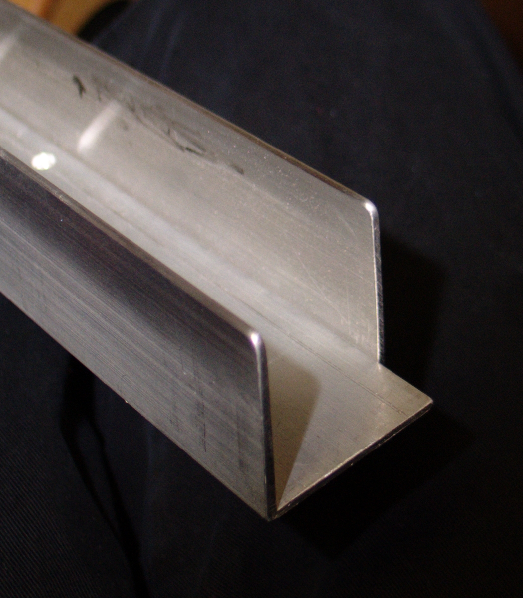
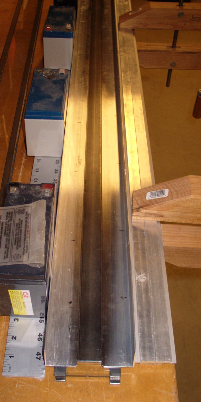
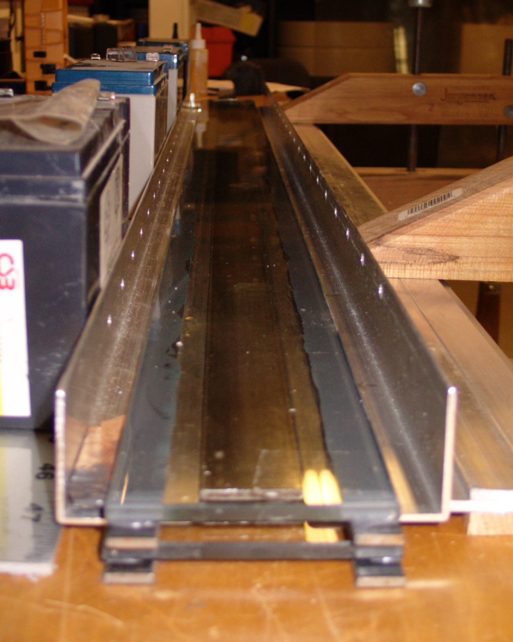
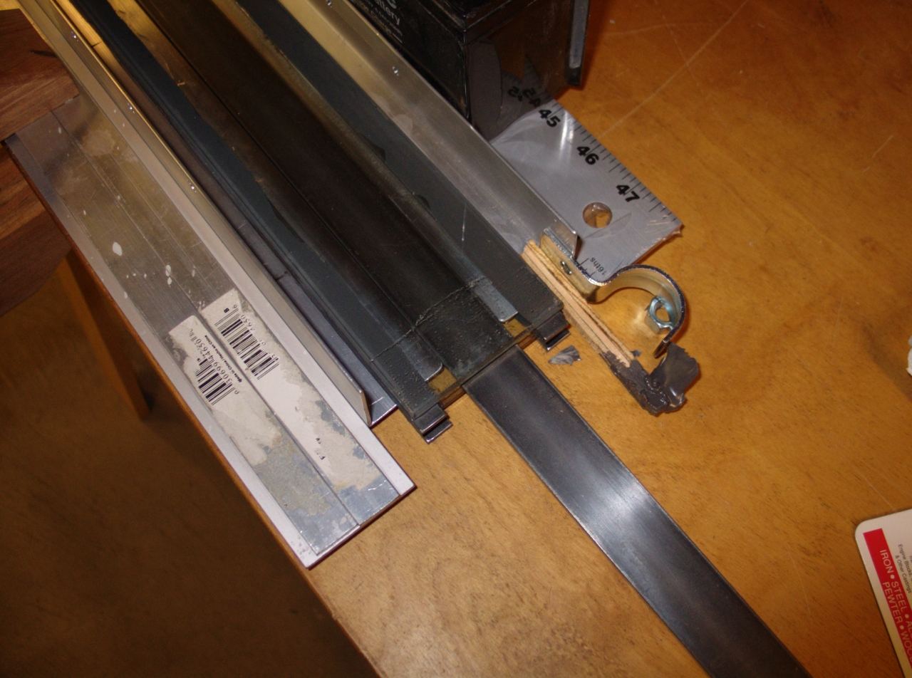
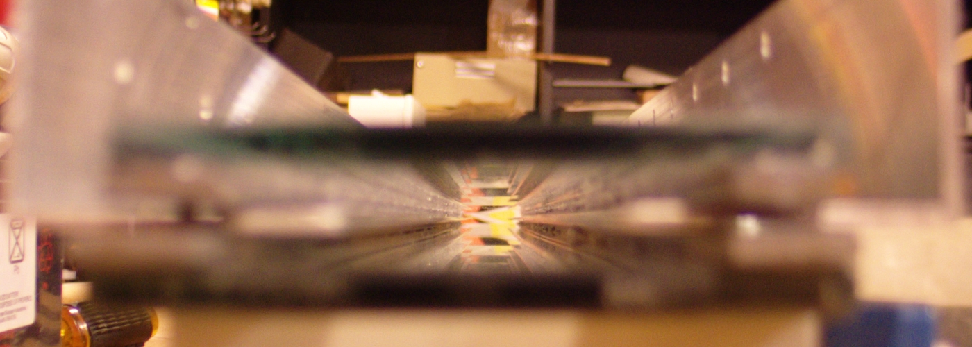
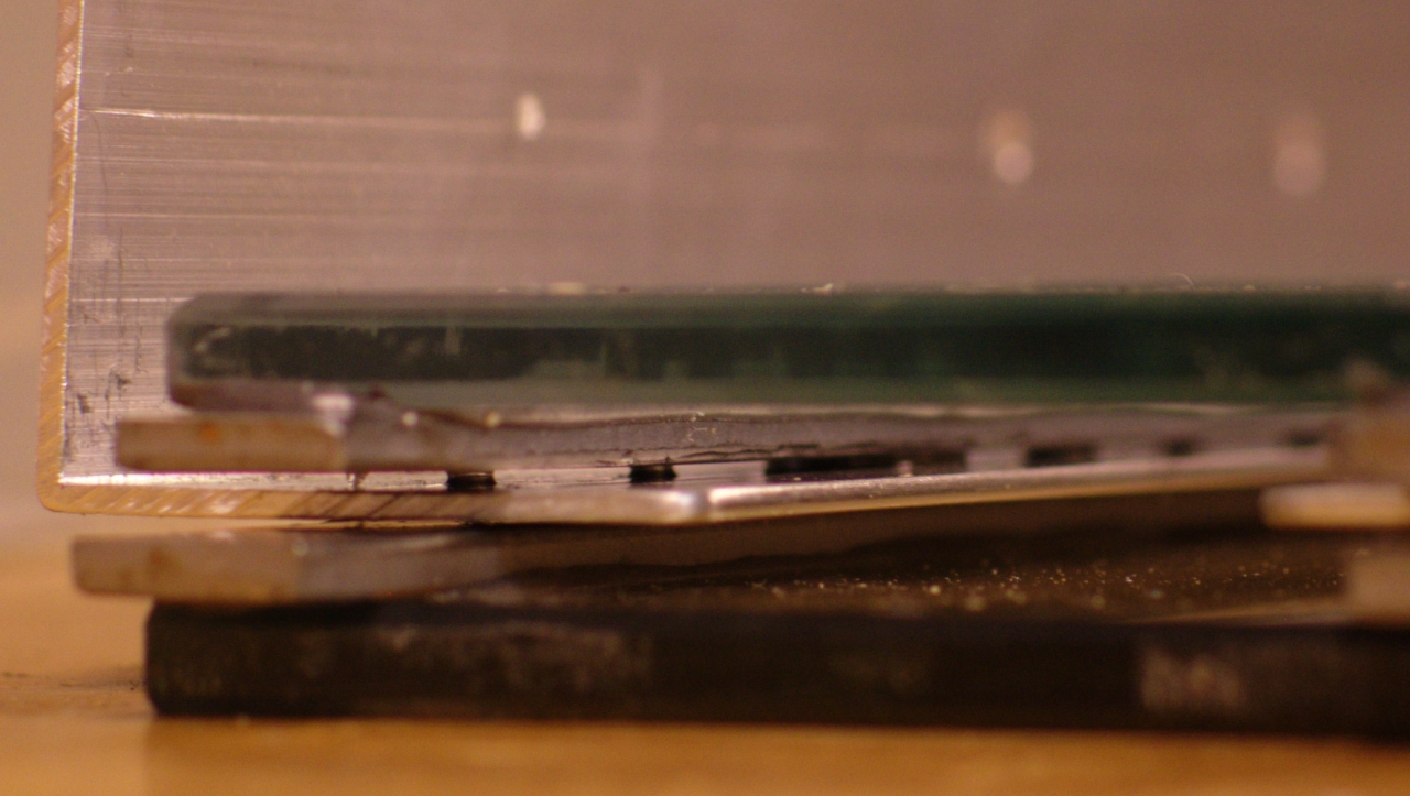
The Preionizer
     +-WMWM-+   +-WMWM-+     +-WMWM-+     +-WMWM-+
     |      |   |      |     |      |     |      |
- o--+-->|--+---+-->|--+--+--+-->|--+-----+-->|--+--o +
                          |
                          3
                          3 (secondary)
                          3
                          |
                          V
                        (Gnd)
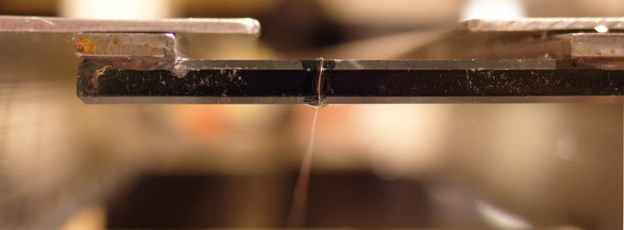
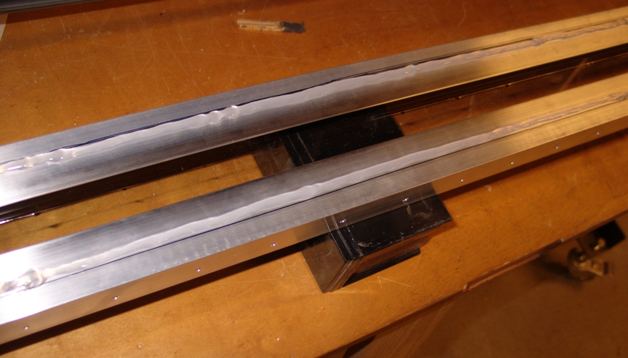
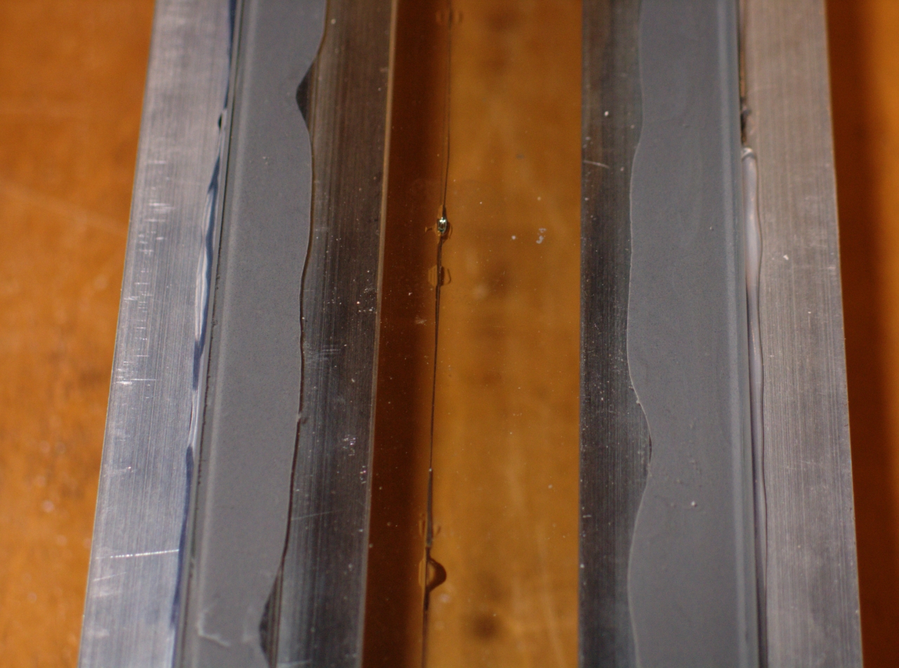
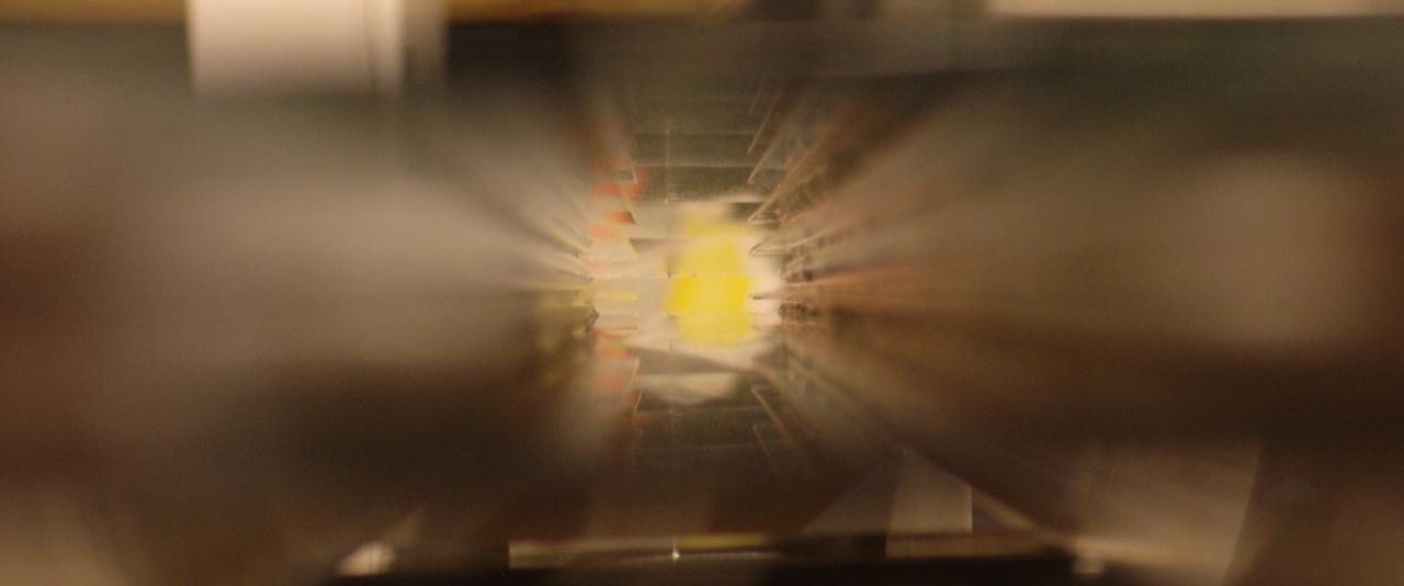
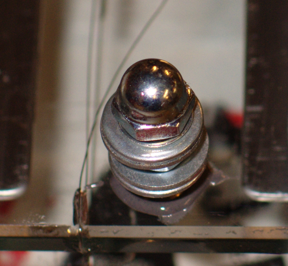
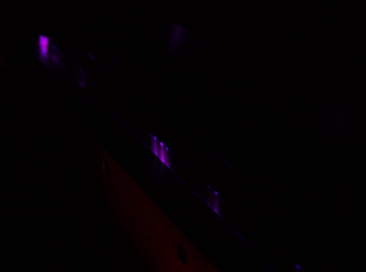
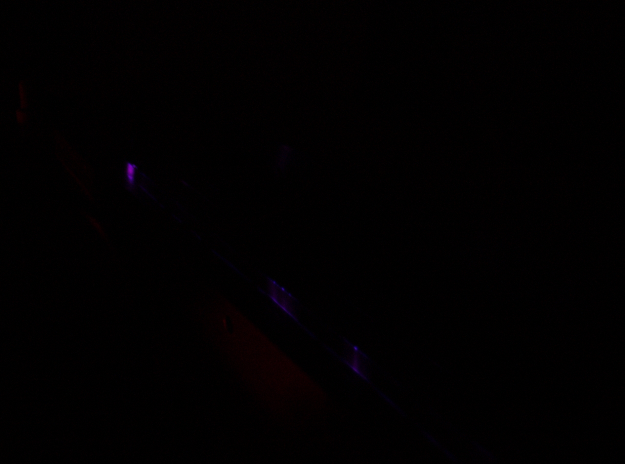
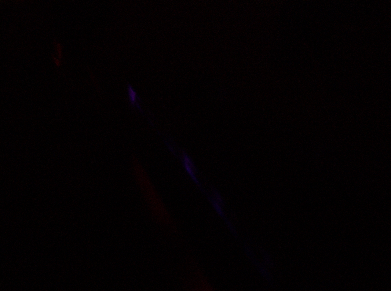
Endpieces: Design and Construction
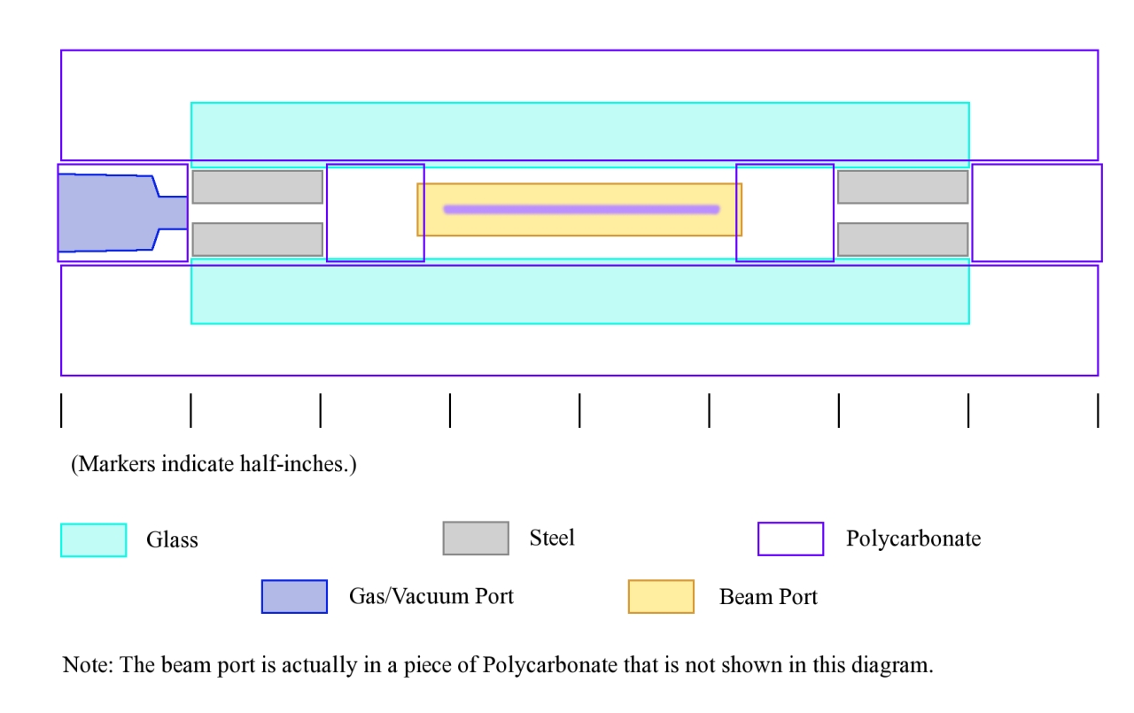
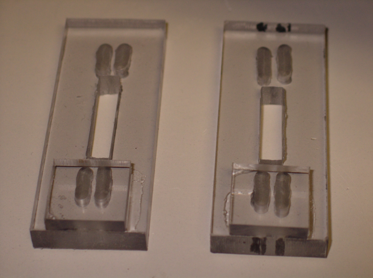
Applying Vacuum
Final Electrical Assembly
Operation and Characterization
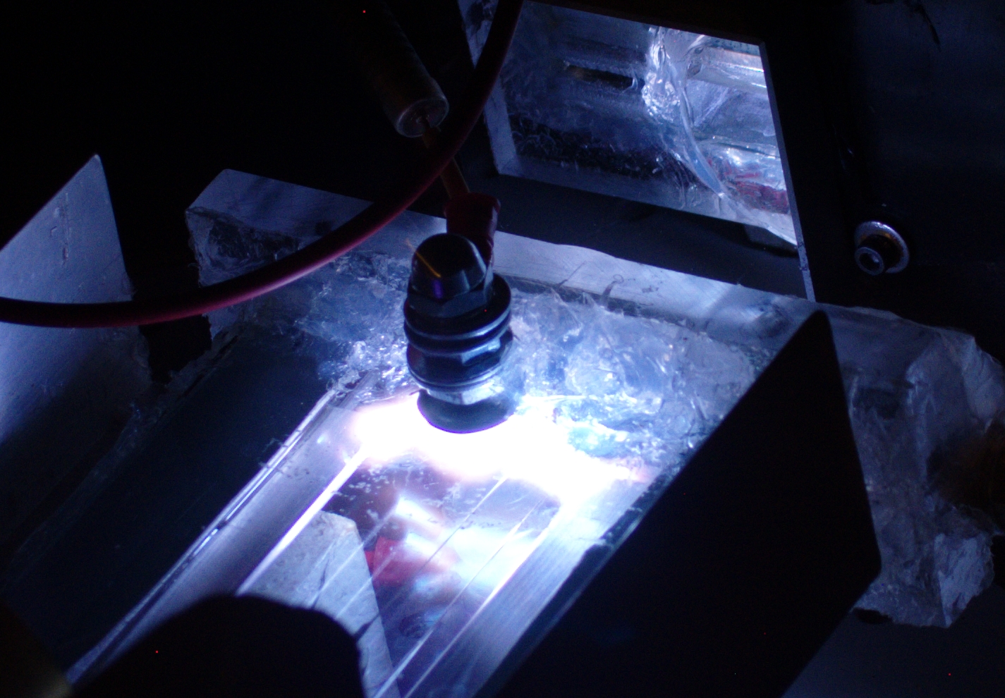
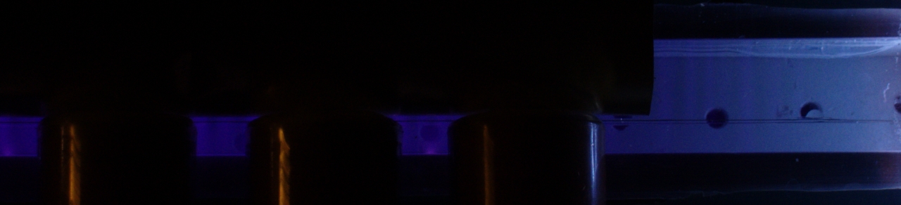
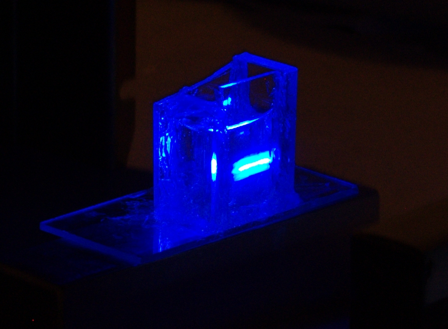
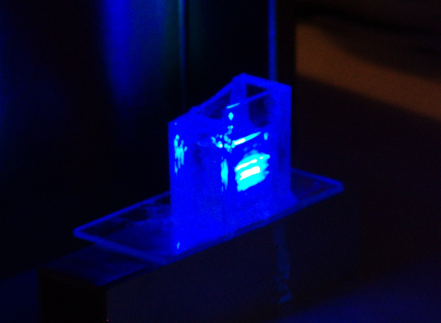
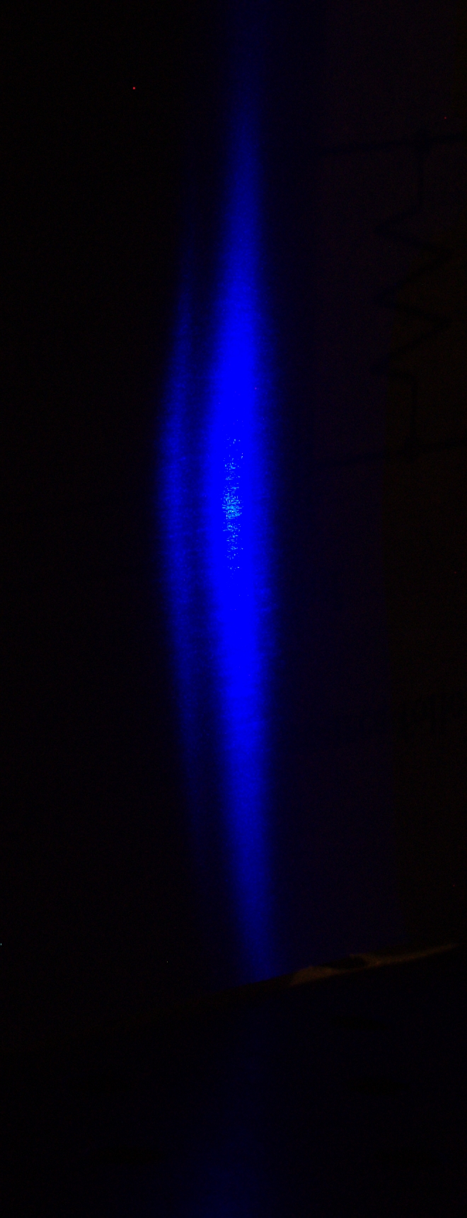
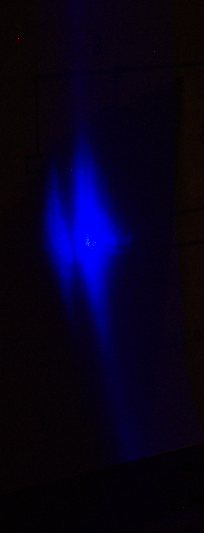
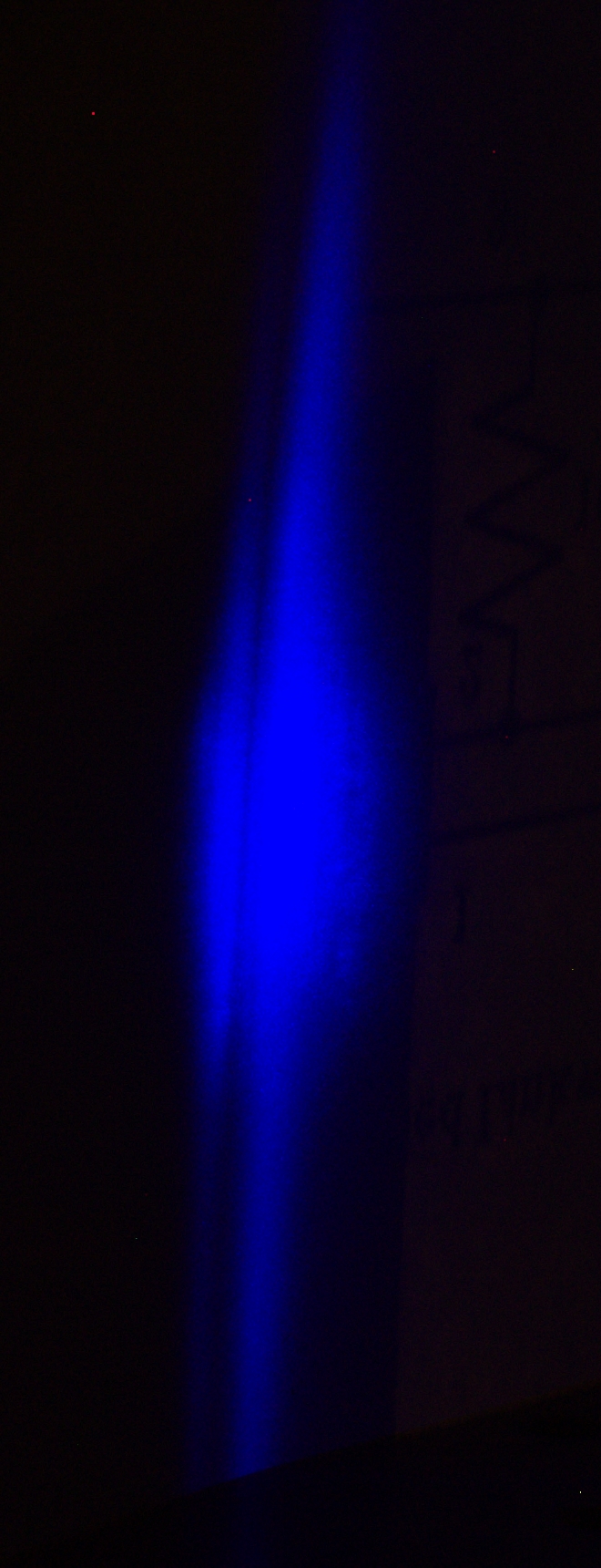
A WORD OF CAUTION
A SUGGESTION OR TWO
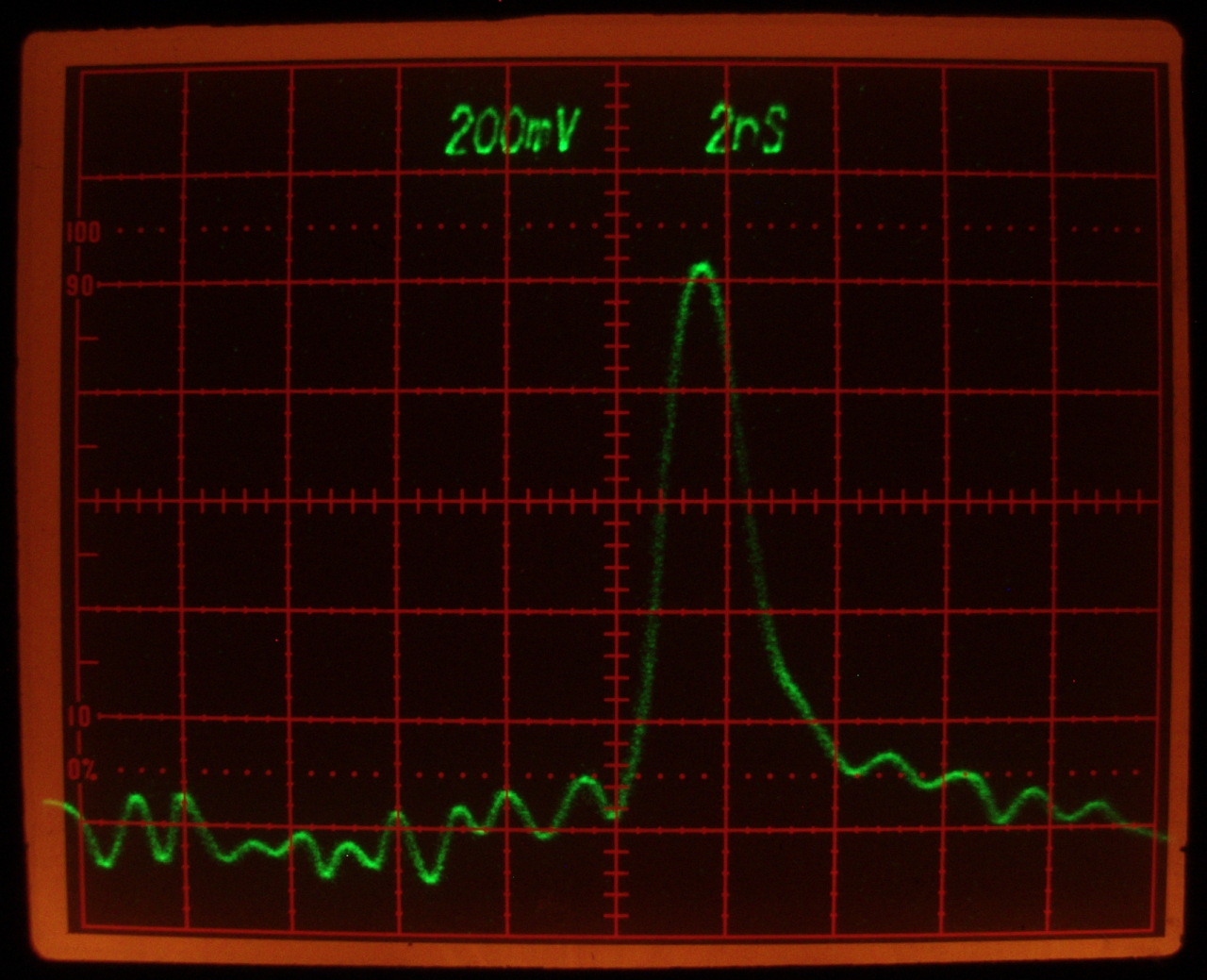
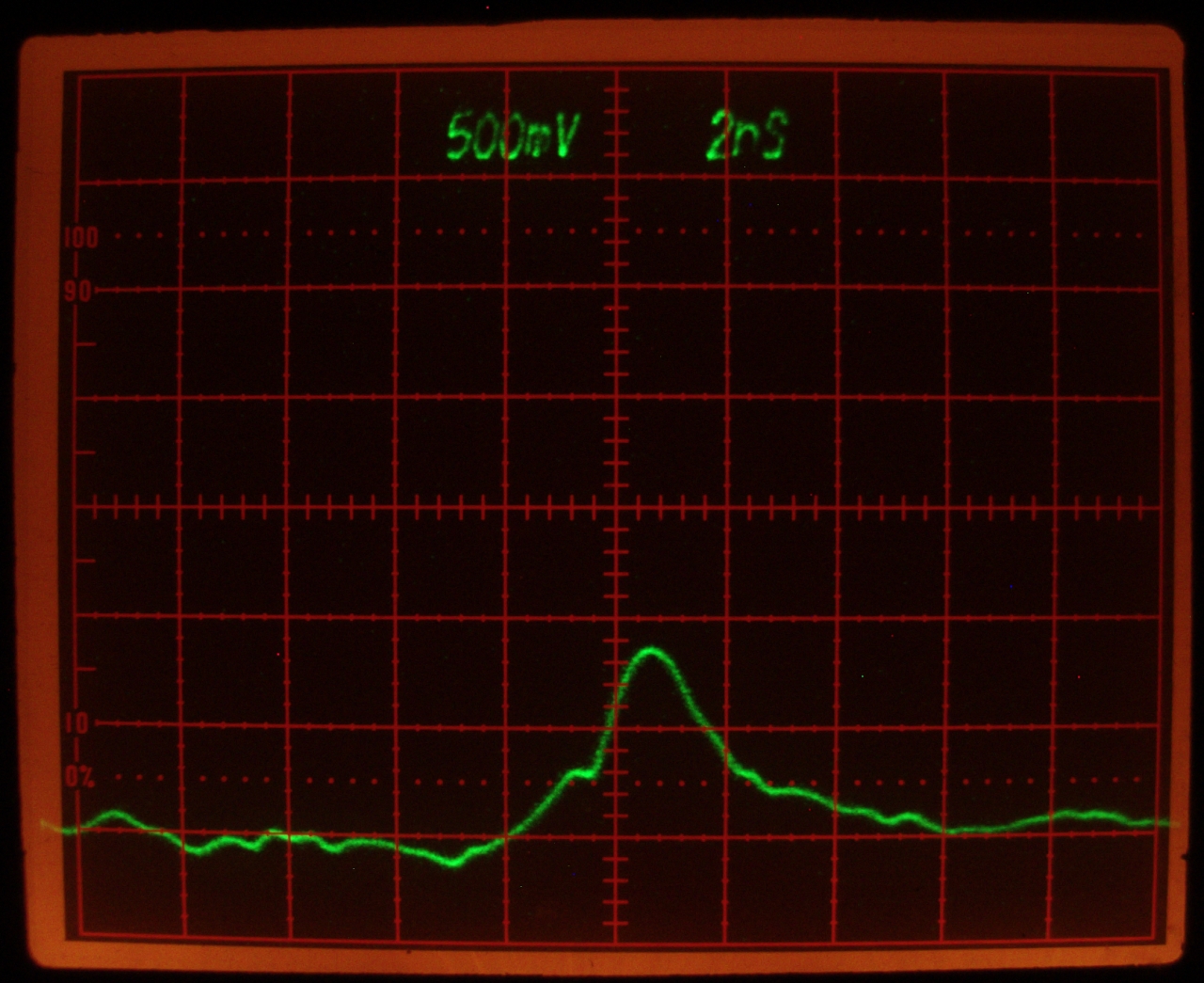
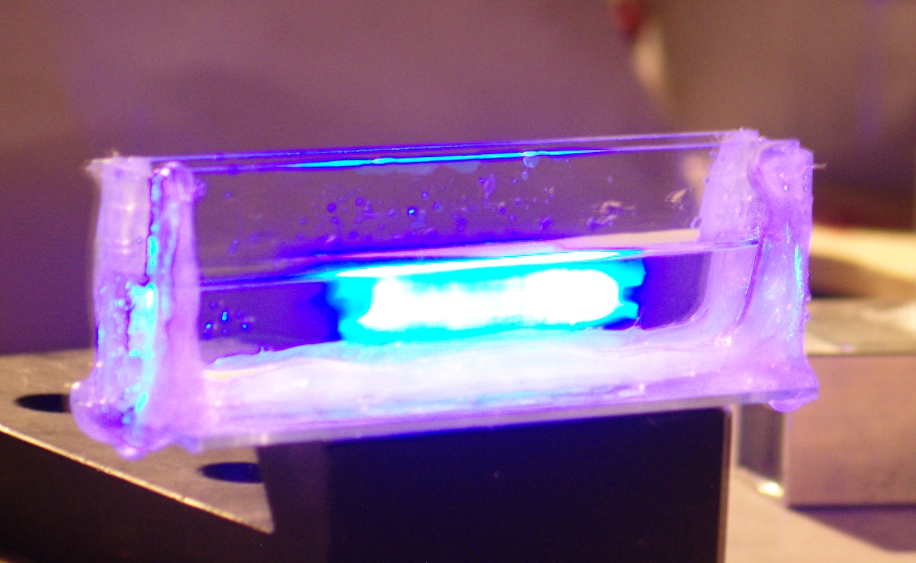
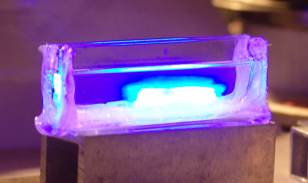
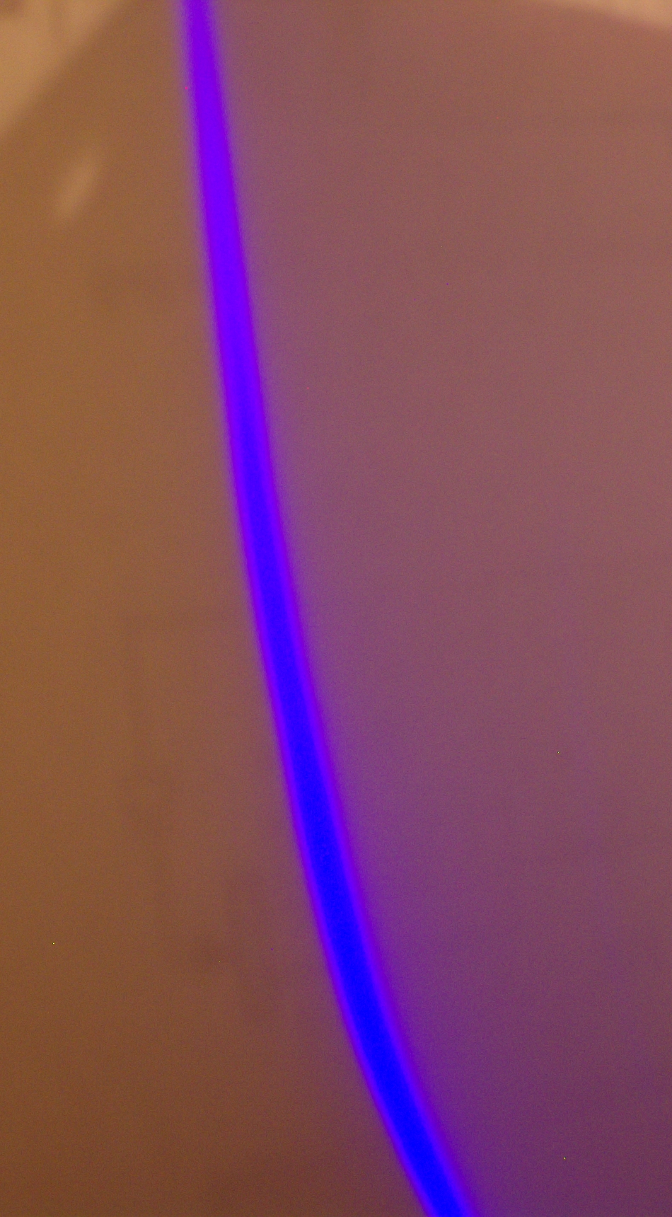
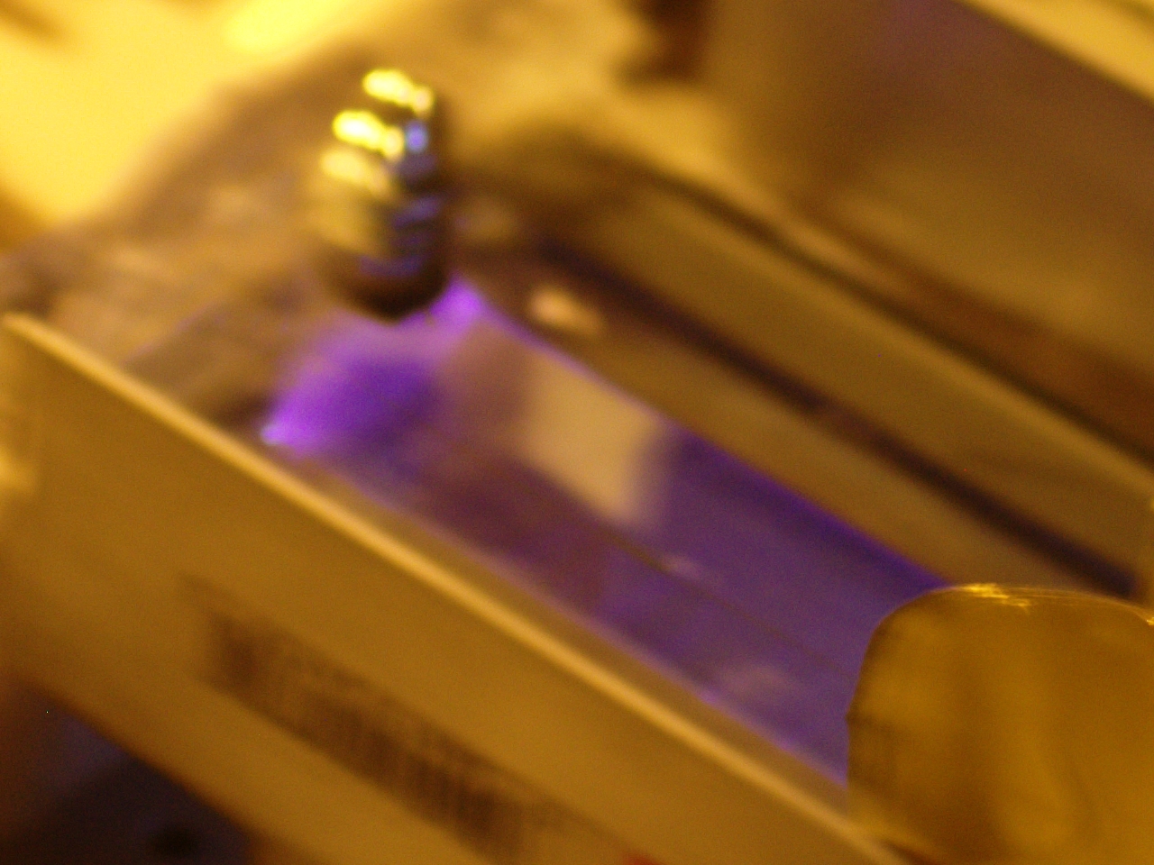
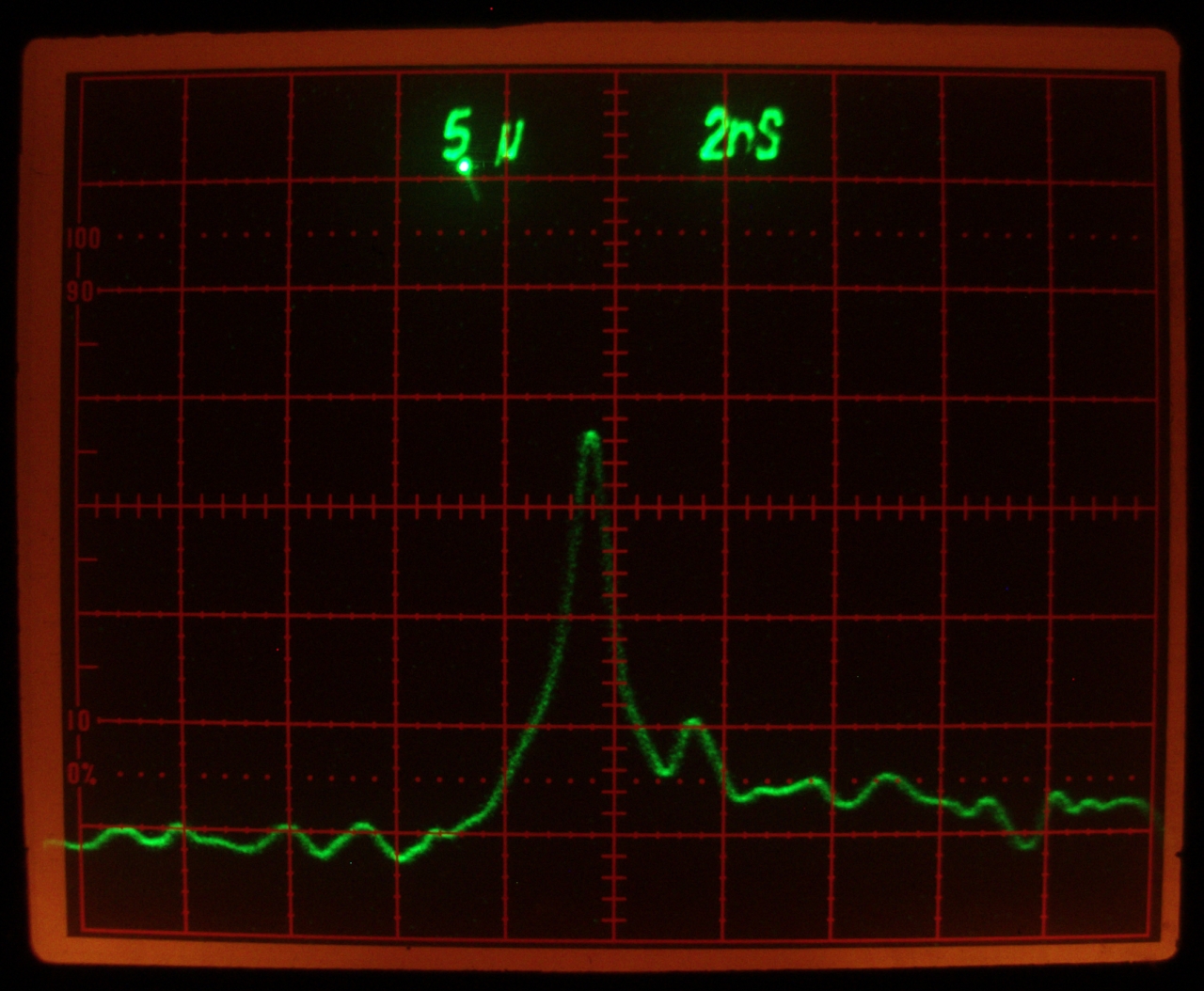
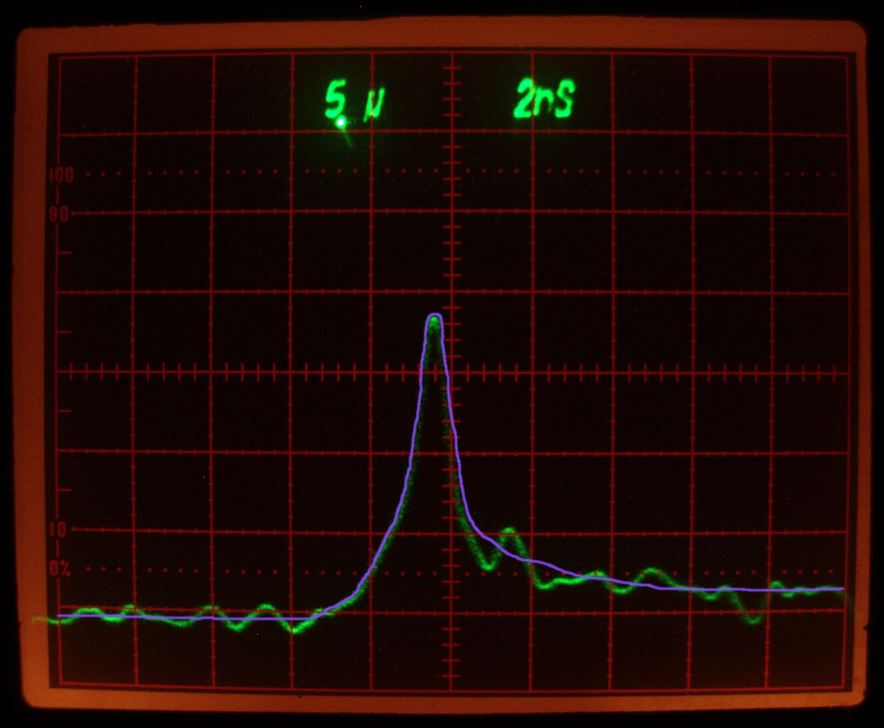
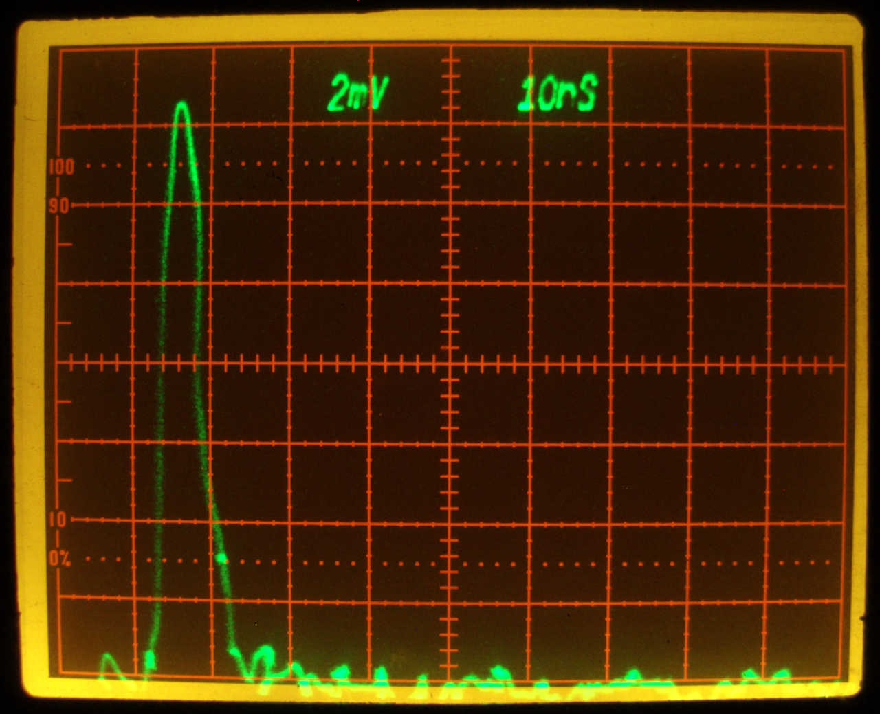
Acknowledgements and Gratitude
This work was supported by
the Joss Research Institute
Contact Information: