(06 December, 2008)
This version is a reprise of the one on the second page of this set, and as I said on that page it has been quite a while since I worked on this laser. I have, however, thought about it a fair amount, and I have decided that it is time to try again. (Every time I rebuild this thing I learn something from it, even when it doesn’t work as well as I might like.)
Here’s the topology I am using for this rebuild:
I haven’t shown the chokes in the + and - HV lines, which keep the EMP from destroying the power supply and also help mitigate the effect of shorting the output of the power supply every time I fire the laser. I should also point out that I have not bothered with the small starting capacitor that I usually put across the spark gap, because the main store is small enough and fast enough that it didn’t seem necessary. The bleeder resistor, which is part of the original design, prevents you from getting a nasty shock if you open up the head and touch the peaker caps, which are not completely discharged when the laser fires.
Please note that while this looks fairly straightforward electrically, it is not trivial to implement physically. The spark gap has to stand on its head on top of the cathode rail, which makes it somewhat difficult to reach the trigger electrode, and requires insulation to prevent the trigger signal from shorting to the cathode outside the housing of the spark gap. Moreover, the positive side of the power supply is grounded, and the negative side is the “hot” side.
If you go back to the first page of this set, you will
observe the fact that this head is built to a slightly
strange design. There are two cathodes, so it generates
two output beams. (You can see this in some of the
photos, below.) I usually just focus them together,
but there may be ways to do interesting things by
separating them, for example a MOPA dye laser where one
beam powers the oscillator and the other powers the
amplifier.
(06 December, 2008)
I am going to use the existing peaker caps, which are already in place from the rebuild that I wrote up on the previous page. There will be either 16 or 20 of them, depending on how much sparking I get near the ends of the laser with all of them in place. They are rated for 30 kV, and I hope to charge them to something on the order of 10 kV. (The “dumper” cap will be charged to 20 kV; but once the discharge starts it’s hard to get the voltage up much higher, and there is almost no chance that I’ll ever reach the theoretical maximum. If I get half of what’s on the main store, I’ll be satisfied.)
[Note, added 23 December, 2008: This has changed. See below for details.]
(from 13 September, 2004)
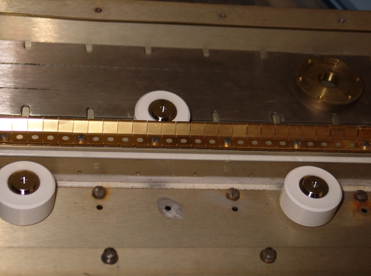
Here’s what the peakers looked like, installed, before I put the distribution rail back into the box:
(You can see the rail and its connector (the round
brass object in the middle) lying against the interior
insulation sheets, at the back of the photo. The
peculiar object in front of the box, on the floor, is
the vacuum regulator that I used last time; I do not
expect to use it this time.)
(06 December, 2008)
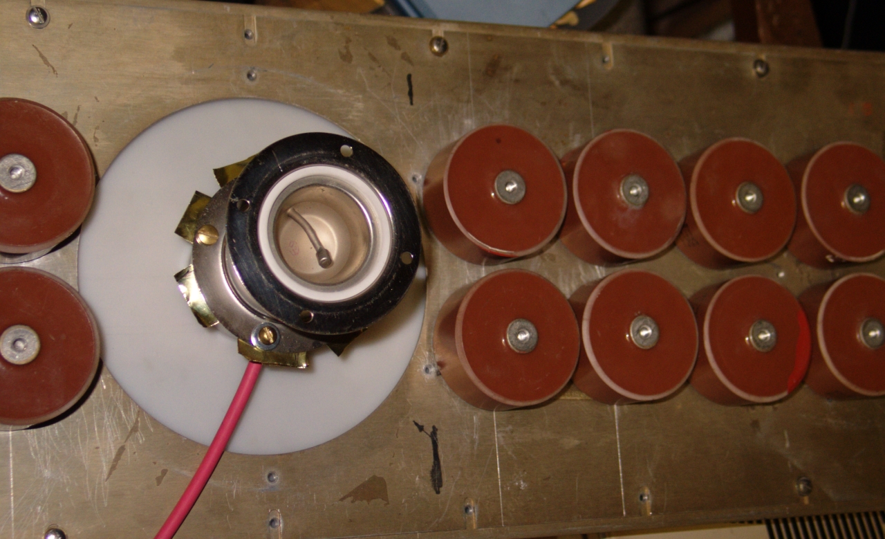
As I have implied in the title, I will be using doorknob caps as the main store. These will be mounted on the lid of the enclosure, to either side of the opening for the switch. I have mounting holes for 8 of these on each side; as they are 2 nf apiece, the total capacitance will be 32 nf. The caps are SrTiO3, and are rated for 40 kV. My best guess is that they came out of decommissioned excimer lasers. (There’s a photo further down the page.)
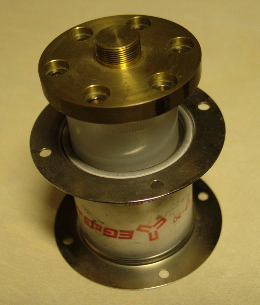
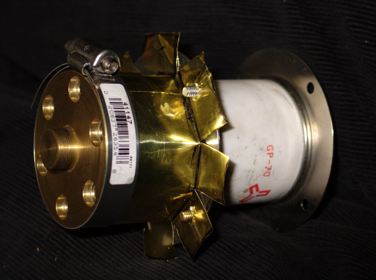
For the switch, I am going to use an EG&G GP-70 spark gap. I’ve tested one of these, and it works fine with our old TM-11 trigger unit. It is rated for use at up to 20 kV in air, it will handle considerably more current than this capacitor array is likely to push through it, and it’s compact. Can’t ask much more than that. Here’s what it looks like:
The top and bottom plates are the same size, btw; they appear different in this photo because the camera was very close to the device. (“Big nose” effect of operating with the lens at a wide angle.)
Here’s my rationale on the current: at 20 kV, 32 nf stores 6.4 joules. If we guess that the effective system inductance is around 100 nh (which is probably better than reality), and if we ignore resistive contributions, the discharge should take something on the order of 170 nsec FWHM (“Full Width [at] Half Maximum”). In actual operation it will probably take longer, but we’re looking for an upper bound on the current, so I will go with this figure. This represents electrical power of a little less than 38 MW, which we can call 40 for convenience. If we guess that peak power occurs when the voltage on the dumper has fallen to about 2/3 of its initial value, we get something on the order of 3000 Amperes. Even if that’s low by a factor of 5, which seems extremely unlikely, we still win: the GP-70 is rated to handle up to 25,000 Amps.
Here’s what the spark gap looks like with its insulating hat on:
When the switch is actually installed, a trigger wire will emerge through a slot in the side of the hat.
Here is the cathode rail connector, to the back of which I have to mount the GP-70:
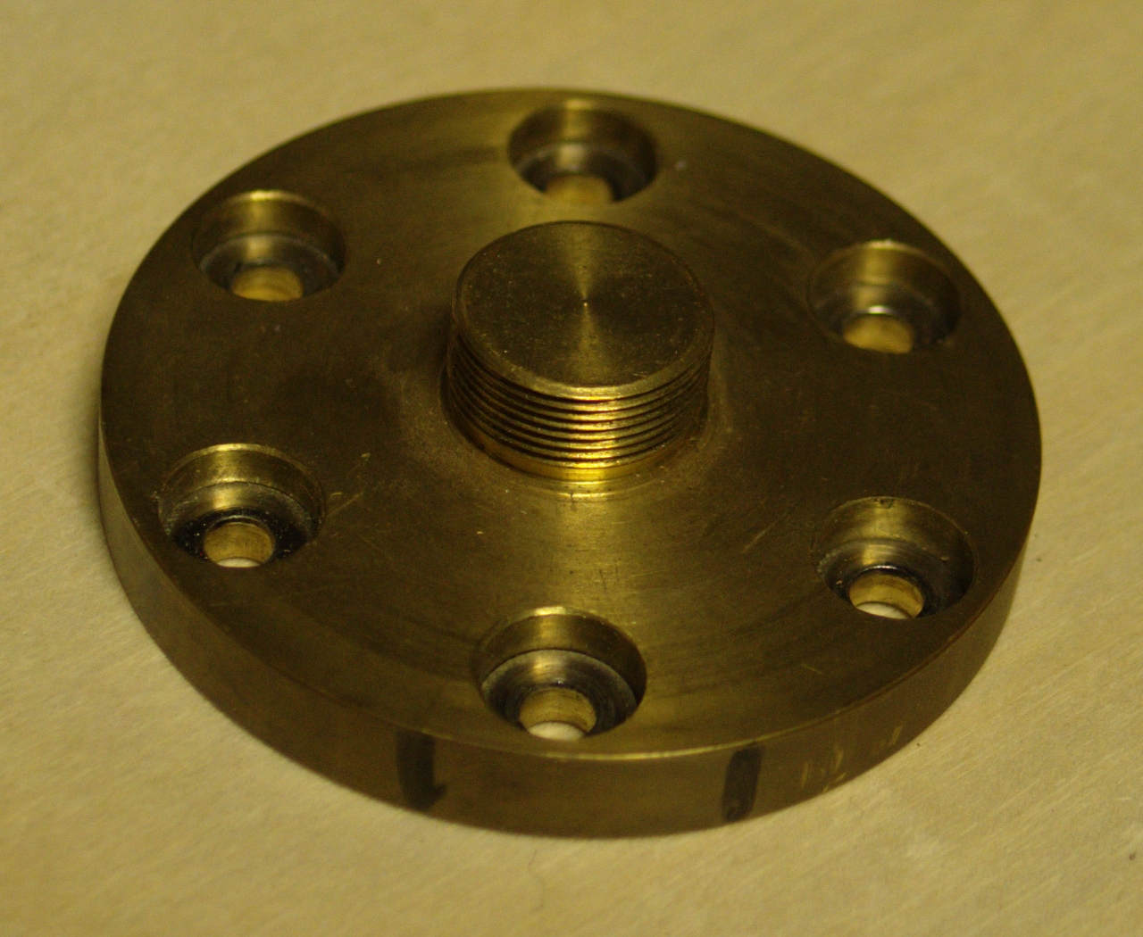
The side facing up in this picture is the side that screws into the rail. In the next photo I have just dropped the connector onto the hat of the switch, so you can see the general arrangement, though it is upside-down here.
(You can see that the size of the connector is not a good match to the size of the spark gap. I still need to make an adapter, and I’m thinking about appropriate design and construction.)
(18 December, 2008)
I may have some ideas about connecting the switch
to the cathode; need to make a measurement or two.
(18 December, 2008, early AM)
I have now wire-brushed the areas on the underside of
the “lid” where the bolts hold it down to
the box. I will have to wire-brush the corresponding
areas on the box, but that only takes a few minutes. I
intend to use silver-loaded conductive material betwen
the lid and the box, and I’ve already applied it
to the attachment points of the 16 large doorknob caps
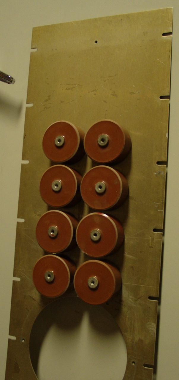
that are installed on the lid. Here is a view of half of
them:
Once the spark gap is attached to the cathode rail, the
only large step that remains is to connect the doorknobs
to the spark gap, and that should be relatively easy.
(19 December, 2008)
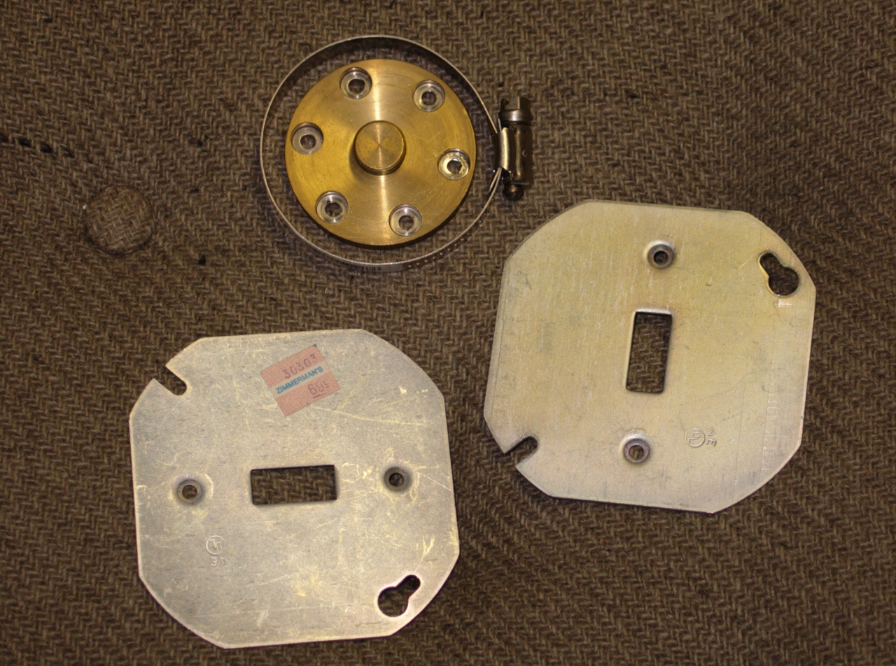
Yesterday I acquired two solid steel switchplates and a
hose clamp at the hardware store. The switchplates
appear to be old stock; they are about 1/16" thick and
relatively smooth, and the pricetags looked very
old. (The newer ones are about half as thick, and are
zinc plated or galvanized.) The existing mounting holes
are almost the right distance apart, and I can just
widen them to fit two mounting holes on the GP-70; I
will have to drill the other two.
I am cutting a round hole in one of them, to
accommodate the hat on the trigger electrode. If
I have enough time and energy, I may also cut the
edge off that one, to help minimize corona from
it to the box, but it is more likely that I will
just put an insulator around it. (A short length
of large-diameter PVC pipe is a good bet for this.)
The other one should be fine as is, because it will
be up in the air at the top of the stack, and will
be at ground potential except during a firing cycle.
(Later, that evening)
I have now cut a circular hole in the middle of one of
the steel plates, extended the existing bolt holes, and
drilled two others. The hole in the middle may be
unnecessary — in order to use this plate on the
trigger end of the gap, I would either have to widen the
hole and put the brass shim through it, or cut the edge
off the plate to turn it into a ring of appropriate
size, and put the brass shim around it. Either way would
be somewhat painful, and I am considering whether I need
to bother with either of them. (Chances are pretty good
that I need at least some sort of ring or
pressure plate[s] to hold the shim in place; there are
only 4 bolt holes in each end of the spark gap.)
(20 December, late evening)
I have successfully constructed the brass shim piece
that connects the spark gap to the cathode connector,
and I have used ultrafine sandpaper to remove the oxide
from the edge of the connector itself so I will be able
to achieve good contact to it. Need to cut a hole in the
brass shim for the trigger wire. This isn’t fancy,
but I think it will do.
(23 December, 2008)
I took the head off the shelf to get it ready for actual
assembly (I want to wirebrush the contact areas for the
lid, and also dust it out a bit), and discovered that
the peaker caps were not present. This may be just as
well; I now have some 1400-pf 20-kV doorknobs that
appear to be intended for laser use, and have much wider
terminations than the 780-pf 30-kV ones that were in
there. True, the decreased voltage rating carries a bit
of risk, but probably not very much. Unfortunately, the
decreased voltage rating also means that these caps do
not stand as tall as the ones I was previously using,
and I have to add spacers to them so that the cathode
rail will be at the proper height. (It has to press
correctly against the phosphor-bronze spring fingers
that carry the current to the cathode.) I have acquired
some brass washers that should serve, and I will be
using dabs of silver conductive paint on all of the
“in-betweens”.
The bolt holes in the head are intended for #6 screws,
so they don’t quite fit #8s; I put a #8 tap
through the 10 holes I’m using, which I could
almost do with my fingers; that enlarged them just
enough. The capacitors are short enough that each of
them will require at least 6 brass washers; looks like I
only have half the number I’m going to need, so I
will be obliged to get more.
I used the existing brass washers under the peakers,
which are now attached to the inside of the box.
(24 December, 2008, early AM)
I was unable to find brass washers of an appropriate
size at the local Home Depot, and acquired some
steel fender washers instead, somewhat against my
better judgement. I am thinking about going out on
the Web and finding The Right Stuff, but will
probably do a preliminary assembly with what’s
on hand. That should tell me whether I’m on
a viable path.
(25 December, 2008, very late evening)
It turned out that the holes in the centers of the
steel washers were not quite large enough for #8
screws, and I had to drill all of them. It also
turned out that 4 per cap was not enough, so I
drilled 53 of the silly things, 2 of which were
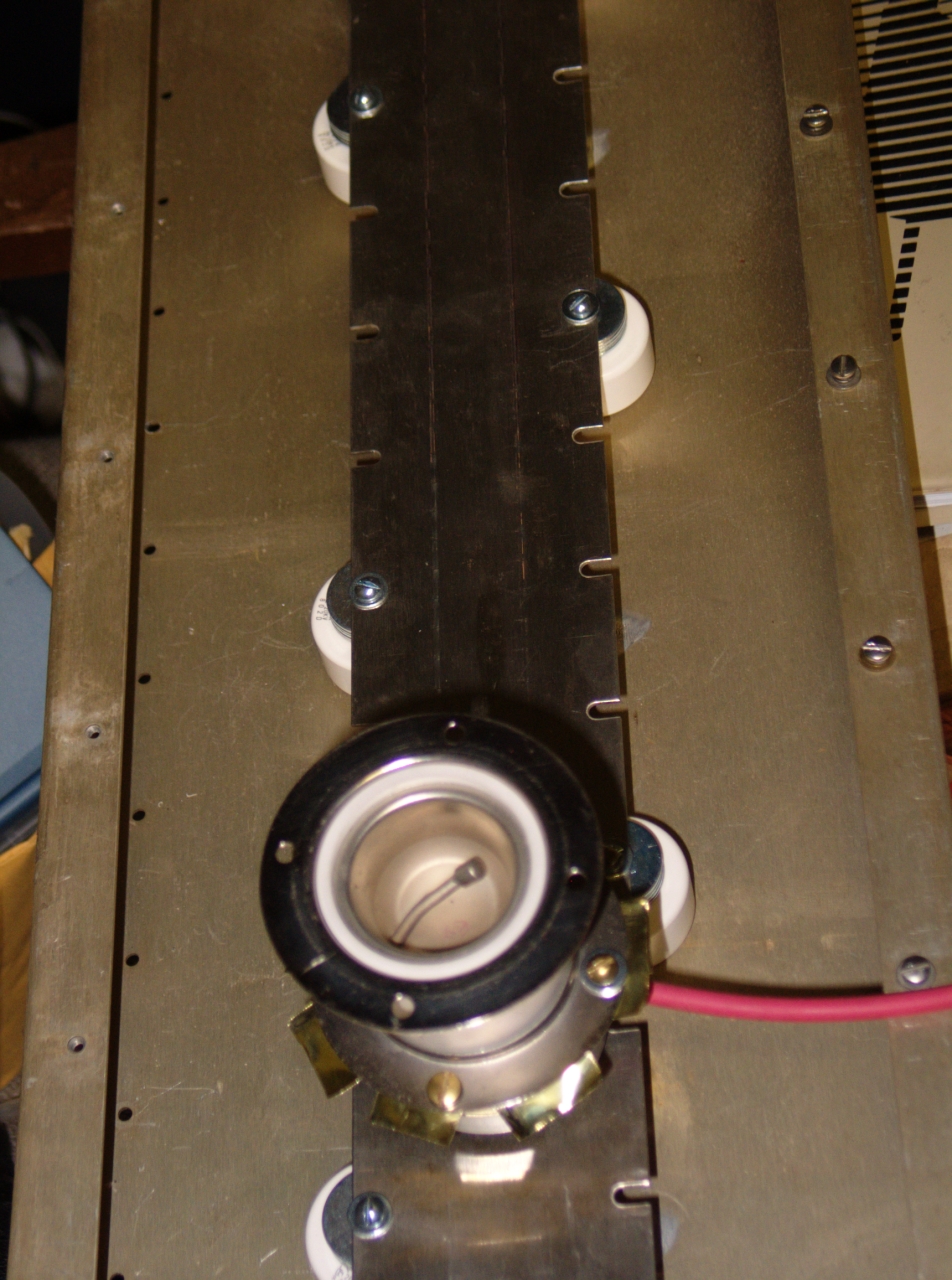
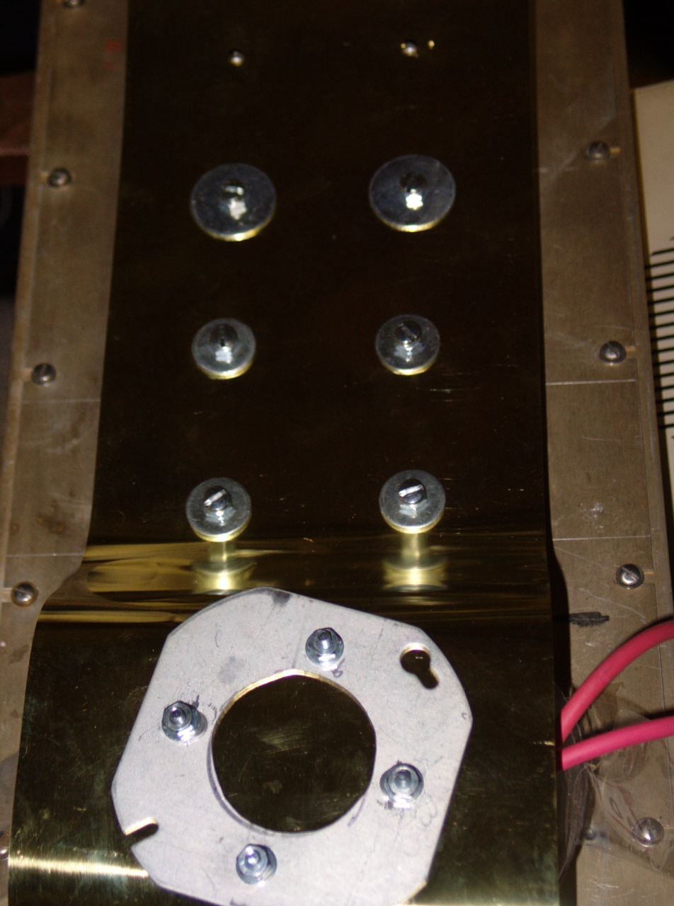
slightly defective. Then I mounted the cathode
connector rail:
With all of the inner guts in place it was time to put
the lid on, so I slid the two insulator sheets into the
box and bolted the lid into position. (Some of the
screws were not yet present when I took this photo.)
Time to fabricate the brass shim piece that connects
the dumper caps to the switch. Here’s an initial
look, with both trigger leads attached, and with an
insulator in place to help minimize leakage from all
those sharp points (which I will almost certainly
remove, later). This was a preliminary assembly; the
bolts that hold the shim onto the switch were not
fully tightened yet.
I had hoped to see first light tonight, but I’m
not quite there yet. Getting very close, though. A few
of the boltholes in the brass shim piece are misplaced
slightly, as you can see in the photo (the last two at
the top; also one on the other side, not visible here),
but otherwise this setup is essentially complete. Once I
tweak the holes (trivial; should take about 3 minutes)
and get the last 3 screws on, it will be time to check
the vacuum. After that, things should move very quickly
toward operation.
(Late afternoon, 26 December, 2008)
The laser is now on the bench, and I have acquired the
polyethylene tubing I need in order to attach it to the
vacuum pump and the nitrogen supply. I checked the
vacuum manifold and pump, and although it would never
pass muster on a real vacuum system, it is more than
good enough for what I’m doing here: goes down
smoothly and swiftly to well under 1 Torr, and takes
several minutes to come back up over 10 Torr when I turn
the pump off. (A real vacuum system, even with just a
roughing pump, would go down to a few microns, and would
take days to come back up.)
(about 6:30 PM, 26 December, 2008)
I have now operated the laser. It is quite well
behaved. There are needle valves on the inlet and
outlet, which give me some control over the pressure,
and I have a gauge on it. I ran it with indicated
pressure as low as about 12.5 Torr, and as high as about
42 to 45 Torr, above which there is sparking at the top
of the bleeder resistor that keeps the peaker caps
discharged between shots. (It is very close to one of
the support legs, and I may paint insulating varnish
on it later, if I decide I don’t need it as a
safety to prevent overvolting the peakers.)
The early appearance is that something around 30 Torr
will be optimal. The fact that there are small air leaks
in the gas/vacuum manifold is not a problem: up to about
0.5% oxygen is not harmful, and in fact about 0.3% is
actually slightly helpful. I do not have any really good
way of calibrating the gauge, and it is connected to
tubing at some distance from the head itself, but both
the head and the gauge are between the needle valves, so
it is probably reasonably close. It is also moderately
repeatable and settable, which is important both for
characterization and for optimization.
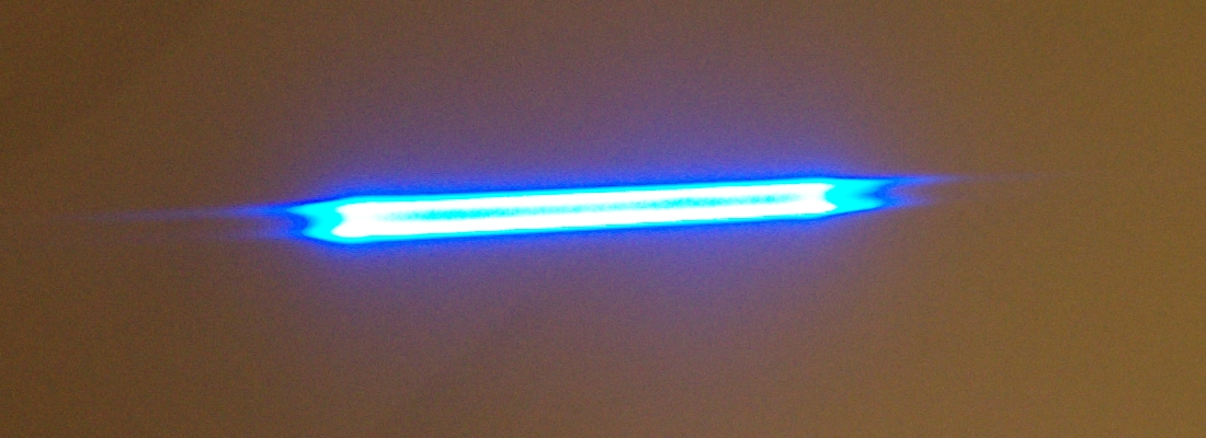
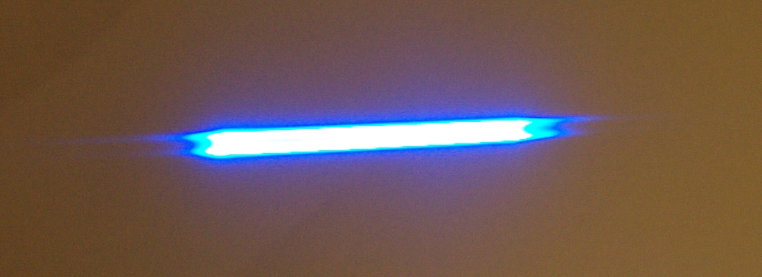
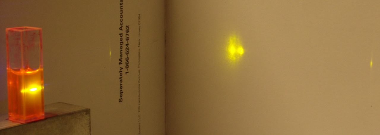
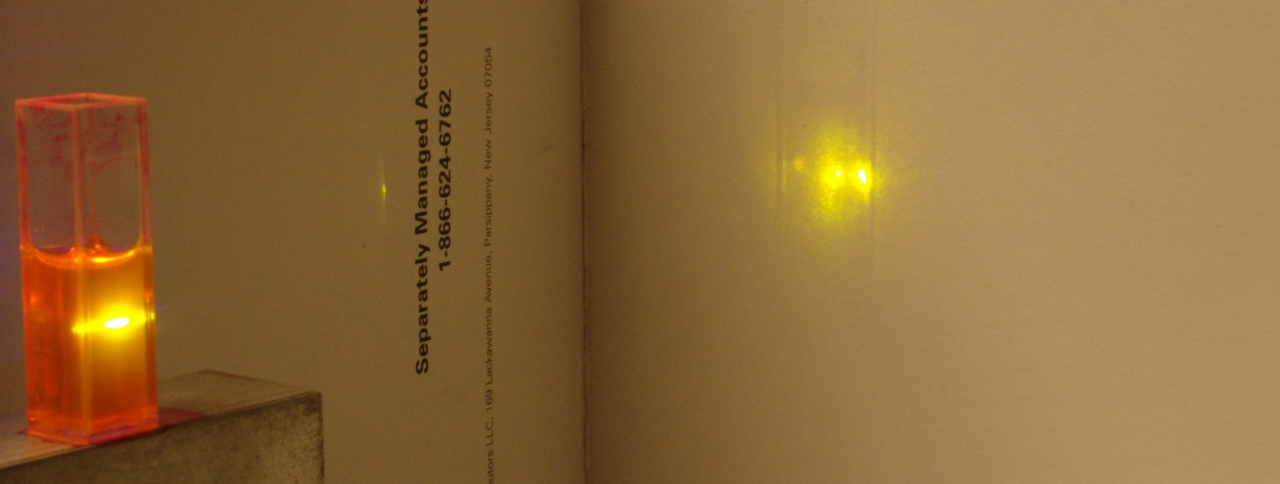
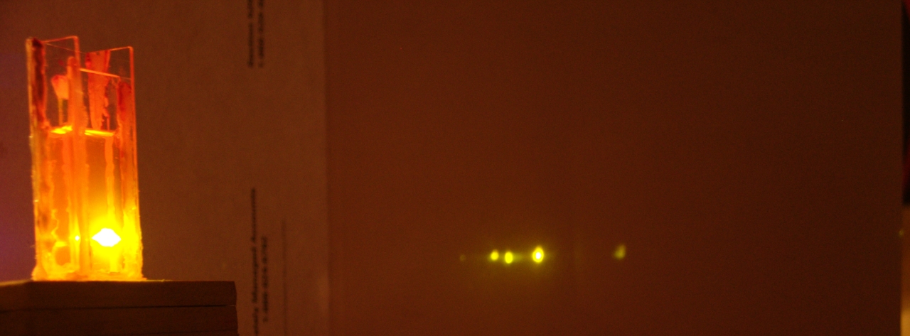
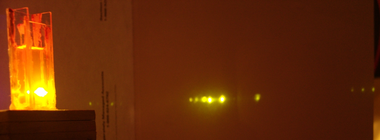
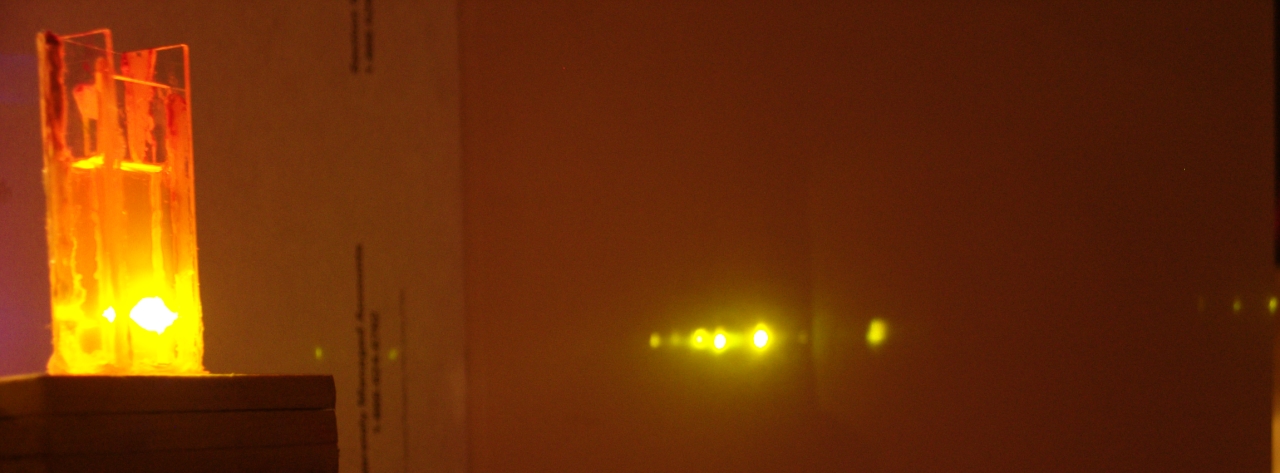
The photo on the left shows the output at 40 Torr or a
bit higher; the odd structure of the beam is evident in
the photo. Unless I am misremembering, the photo on the
right shows the beam with the pressure between 25 and
30 Torr. The camera is better at distinguishing between
these than the eye: in the photos you can clearly see
that the laser is much brighter at the lower pressure,
but when I was taking the pictures I couldn’t see
much difference. Both of these, btw, are actually
pictures of the fluorescence of the paper target, not
the beam itself.
Before I proceed to the next section I will probably
try running a small dye laser, to see how well I can
focus the beam.
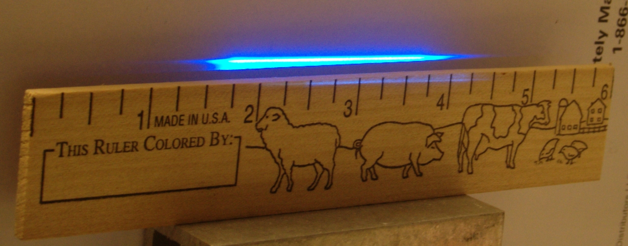
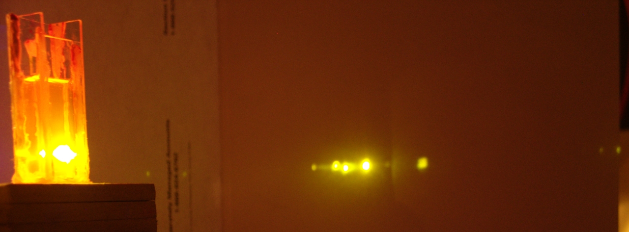
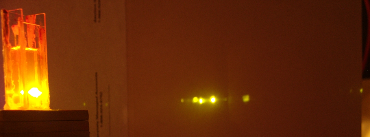
[Note, added the next day: It occurs to me that I failed
to provide a sense of scale, so here is a photo with a
ruler. Notice that the central bright part of the beam
is at least 62 mm long. The spacing between the cathode
and anode is almost certainly about 60 mm, which is
remarkably large for this sort of laser.
As you can see, the laser is not quite level on the
bench yet. I shimmed it, but apparently not quite
enough, and I will be adding more shims.]
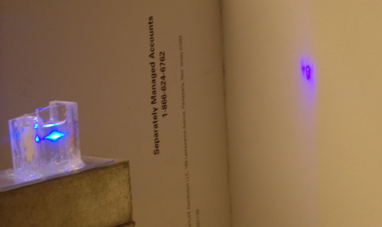
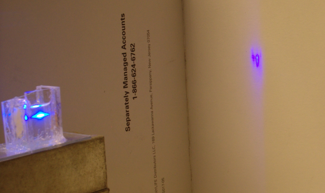
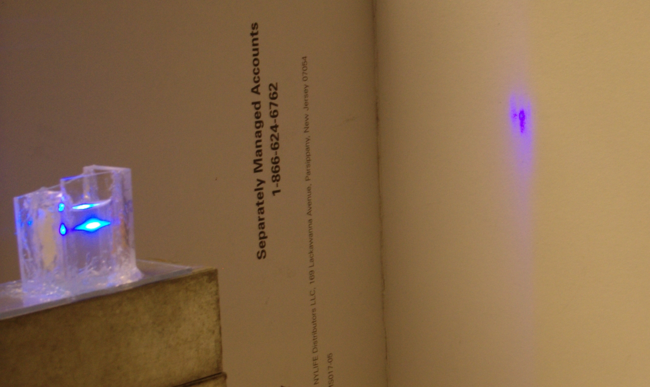
(A little later, Friday evening...)
For the next three photos, I dissolved 2 drops of Dharma
Trading Company
“Optic Whitener”
in a cc or so of 95% ethanol, in a small cuvette that I
built a few days ago. Optic Whitener is probably the
best DIY laser dye I have found so far, and it lased at
all pressures I tried. I didn’t seem to see much
dependence of the output on pressure, though there was
clearly less at the highest pressure I tried (just under
38 Torr, photo on the right), and slightly less at the
lowest pressure (about 10.6 Torr, photo on the left)...
Some of the color you see on the target is probably just
the way the camera “sees” output of the dye
laser, which is actually a beautiful violet; some of it
may be fluorescence from the target; and some of it may
be the brightness of the dye output overloading the
camera’s sensor a little. The difference in color
between the cuvette and the wall, however, is real.
This particular cuvette, btw, is somewhat asymmetric,
and at some point I will try to provide a picture that
shows the differences between the two outputs. When you
effectively have only one mirror on a high-gain medium,
you can get some odd little effects, and when you have
two low-reflectance mirrors on a short-pulse laser you
can get even odder effects. The nitrogen laser itself,
of course, at least in most low-pressure designs, is one
example, as it is typically operated that way; but the
cuvette is different because the “mirrors”
reflect only about 6% (assuming that they are fused
silica, as the ones on this cuvette happen to be), and
you get output at both ends of the medium. I am
considering constructing a more complex cuvette, with
adjustable windows so I can tweak the angle of the
reflection. If I do that I will probably use sapphire
windows on it, to get about 14% reflection, and if it
works it will become a
“TJIIRRS”
entry. Designing such a device, however, is not exactly
trivial, and I haven’t had time to give it careful
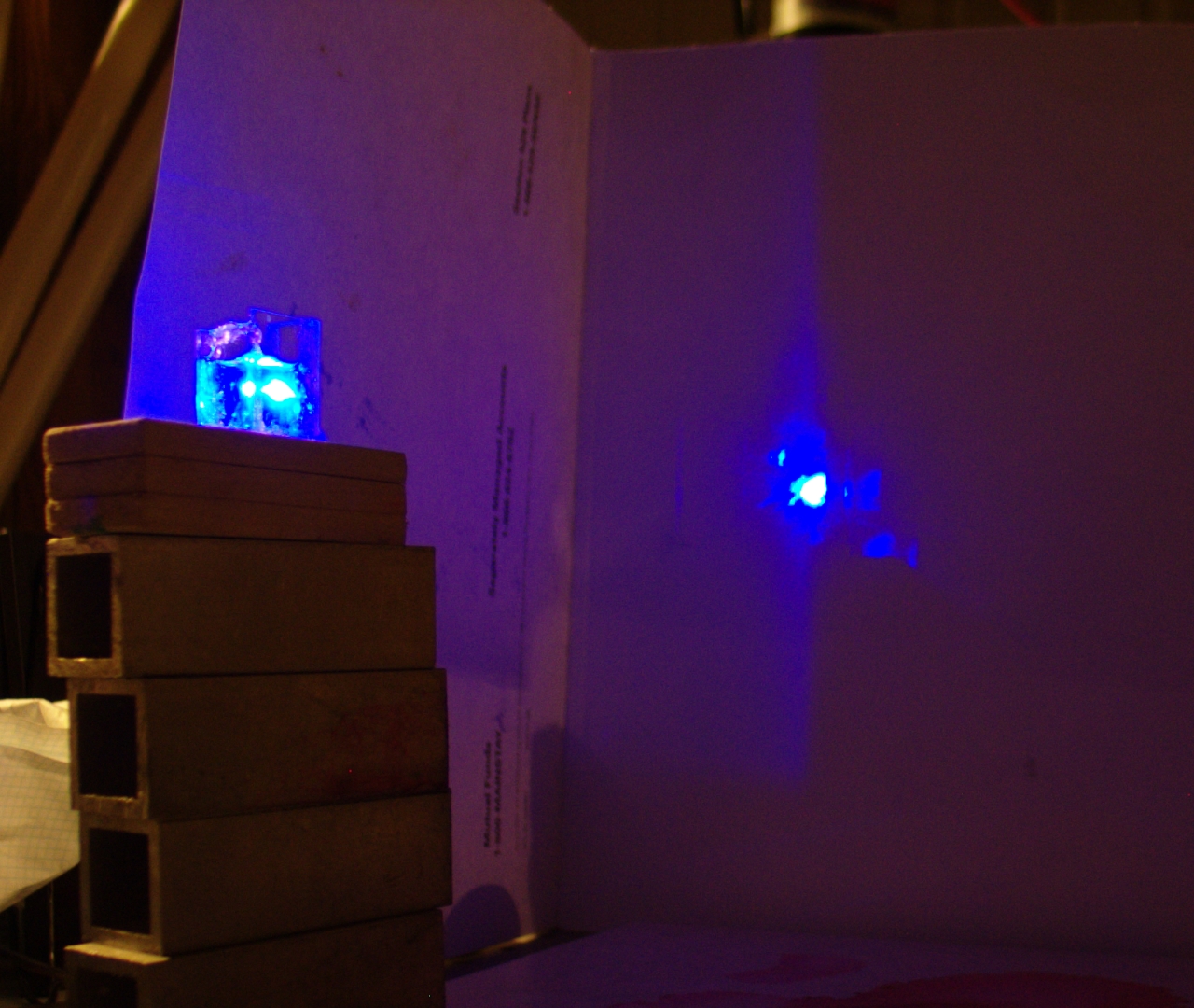
thought yet. Meanwhile, here is a photo with one mirror
in place and a bit less room light, taken with the
pressure gauge reading 16.9 Torr:
Here is some mediocre (I think it’s only about 85%
pure, definitely not laser grade) Rhodamine 6G
dissolved in 99+% isopropanol, with the nitrogen at 24.3
Torr indicated pressure. In the first photo, the dye is
using just the reflections from the walls of the cuvette
(no external mirrors). For the second photo I have added
(and more or less aligned) one mirror, which is not
visible here:
With both dyes, the nitrogen laser’s output was
approximately focused on the front of the cuvette, but I
did not make much effort to optimize it, and I noticed
that the dye was happy to lase with the cuvette even
roughly positioned. With the Rhodamine in place I tried
turning off the supply of nitrogen, and the dye
continued to lase as the indicated pressure went down to
5.3 Torr, probably with a certain amount of air in
it from leaks. At that point I shut down the system.
This laser is clearly performing quite well, and I am
extremely pleased with it. I suspect that a generous
application of silver-conductive material to the lid
attachment points and the stacks of washers on the
peaker capacitors would improve it even more, and when I
have both time and enough silver goop, I will probably
try that. In the meanwhile, however, I certainly
can’t complain.
(27 December, 2008)
I think that if I can get the old Tek 7104 to behave,
it is about time to check the pulsewidth. See below...
(Noon, Saturday, 27 December, 2008)
My first attempt at taking a pulsewidth measurement has
failed. Although the EMP from the laser does not seem to
bother the Canon G3 camera (which was sitting on a tiny
tripod right on top of the TM-11 trigger unit when I
took all of the photos above!), it certainly bothers the
oscilloscope. I am getting only hash on the screen,
regardless of whether I have the detector turned on or
off, and even regardless of whether it is connected.
When I get a chance I will try powering the scope from
a different source, and moving it farther away from the
laser.
(That evening)
My second attempt was slightly improved, but something
still isn’t right. Here are two traces that I took
with the vacuum gauge at 14.4 Torr, but I’m not
sure how much of that was nitrogen, so take it with a
grain or two of salt.
The scope faithfully assures me that these were showing
2 nsec/division, which would mean that the nitrogen laser
pulse is about 1.5 nsec long, FWHM. That’s highly
unlikely; at 2 nsec/div, the pulse should fill about half
of the screen. Notice all the noise, as well. I do not
trust these traces. OTOH, it is clear that the peaks
were generated by the laser: if I change the gas pressure,
the peak height changes.
(afternoon, 28 December, 2008)
I am attempting to shield the bench a bit, by
connecting lengths of hardware cloth to it and
running them up toward the ceiling. I don’t
think I want to try building anything resembling
a Faraday cage, as it would be impossible to get
power and control in or out, but I hope that I
can reduce the electrical noise at least a little.
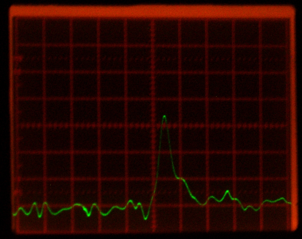
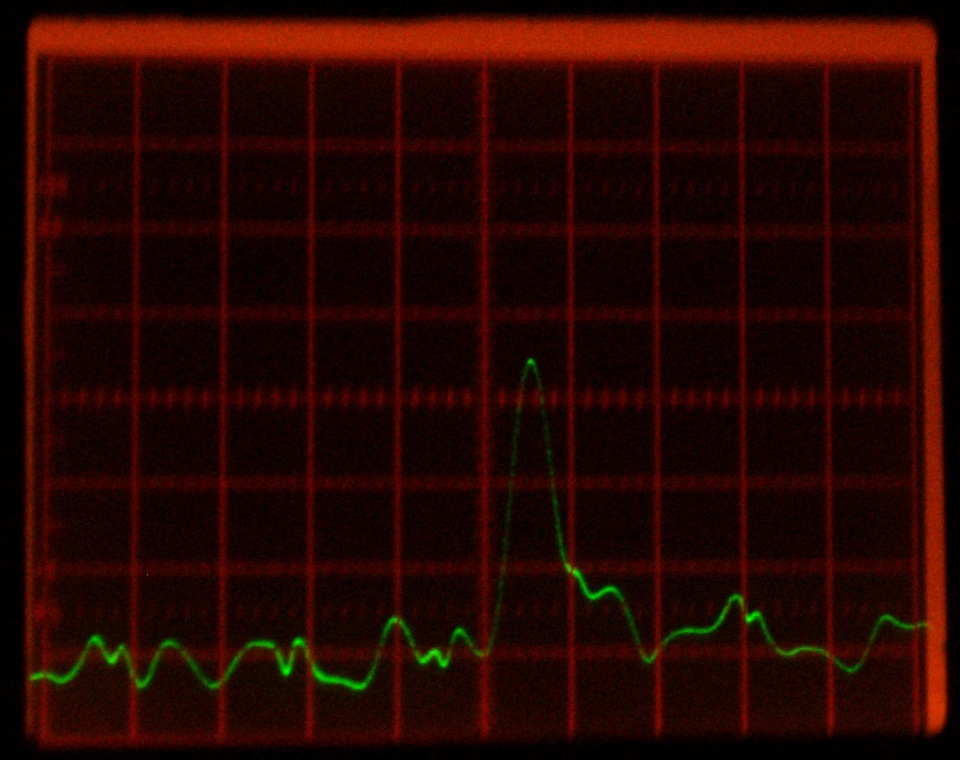
(later that evening)
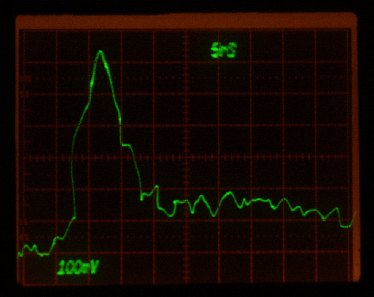
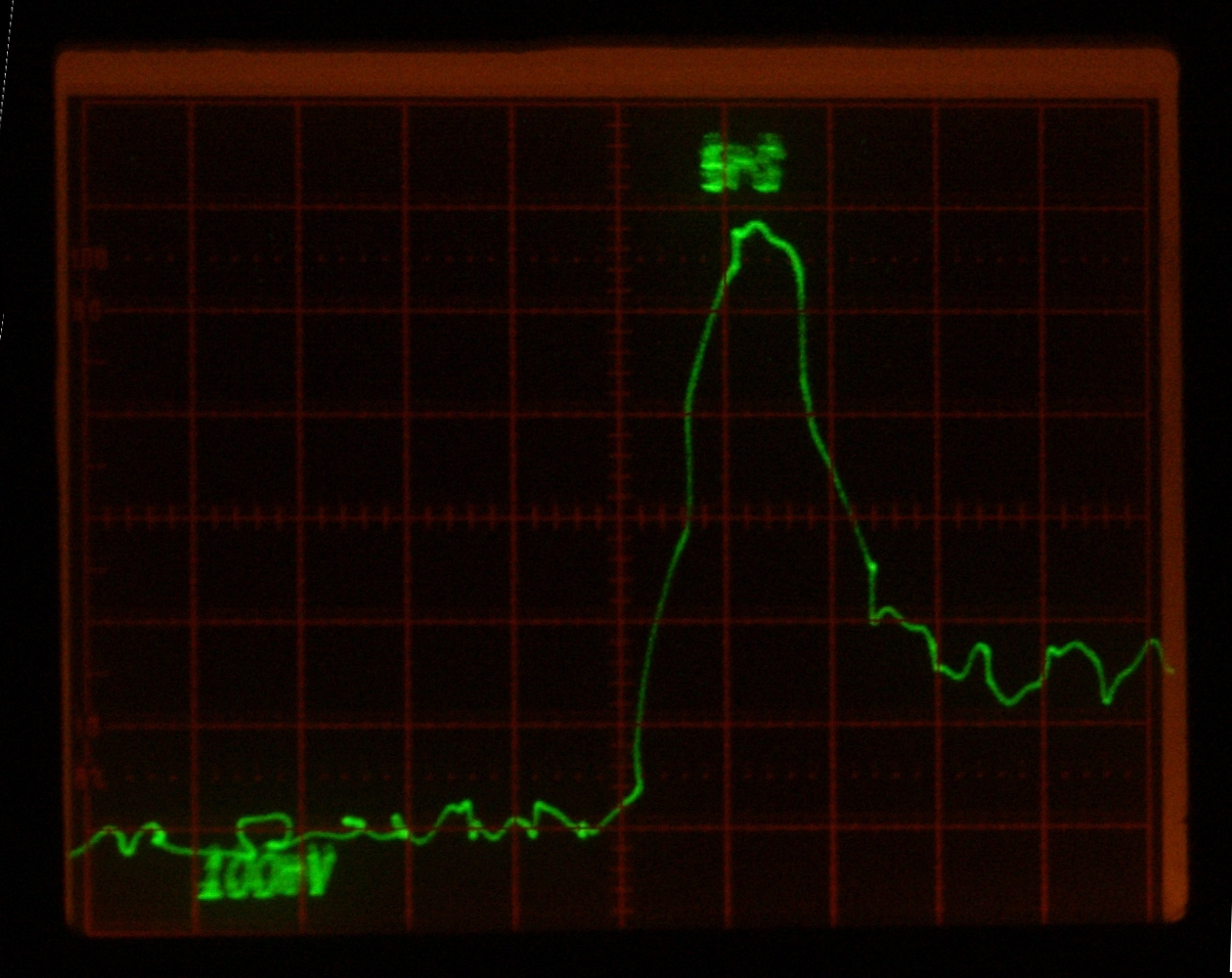
I had to retreat to the 600-MHz vertical amplifier
plugin, and there is still rather a lot of noise, but at
least I was able to capture some traces. Here are two of
the least nasty ones:
Despite the noise and wobbles, I tend to trust these
more than I trust the ones I took yesterday. The FWHM
pulsewidth is 8 or 9 nsec, not just on the two images
here, but on several others as well. Next, I get to
measure the pulse energy.
(30 December, 2008, early AM)
I set a sensor up with out little homebrew instrumentation
amplifier, and looked at the output of the amp with a
DMM. The sensor head was able to “see” my
hand, and it turned out that reading the output of the
amp with the DMM, which I hadn’t really tried
before because I thought the reading would be too
squirrelly, was actually okay. When I set things up on
the bench and ran the laser into the sensor, however, I
got figures that seemed too small. The best number was
perhaps 12.7 millivolts, and that was after X100
amplification. (I’m using half of an INA 2141.)
...So I swapped out the batteries in the amplifier,
and immediately started getting readings of -1.6 V.
Worse, the sensor didn’t seem to pick up the
IR from my hand. I think I may have to build a new
amplifier board.
(I may move this, later, to a different page.)
(30 December, 2008, early AM)
It may not be easy to tell, because I worked rotation
and shear and perspective magic on the ’scope
photos with the Gimp, but I have been having a rather
difficult time trying to capture traces on the screen of
the scope. It occurred to me, a day or two ago, that I
could probably take an old scope camera and modify it.
I thought I remembered getting one with the scope, and
that turned out to be correct, so I took a look at it.
It consisted of a flange that attaches to the front of
the scope, a large box of electronics and optics, and a
Polaroid film back. Even if we could get film for the
back, we would just have to photograph or scan it, so I
had no qualms about putting the camera part on the
shelf. It turned out to be trivial to remove the box
from the flange, so I did. Then I constructed a very
simple box from scrap plywood, to which I have attached
an adapter that fits the lens shield tube on our Canon
G3. I have a new tube on order, and I will attach it
more or less permanently to the new adapter; the G3
mounts very quickly and easily to the tube, so that
is probably the preferred way to handle this. It
will now be much easier to take pictures of scope
traces...
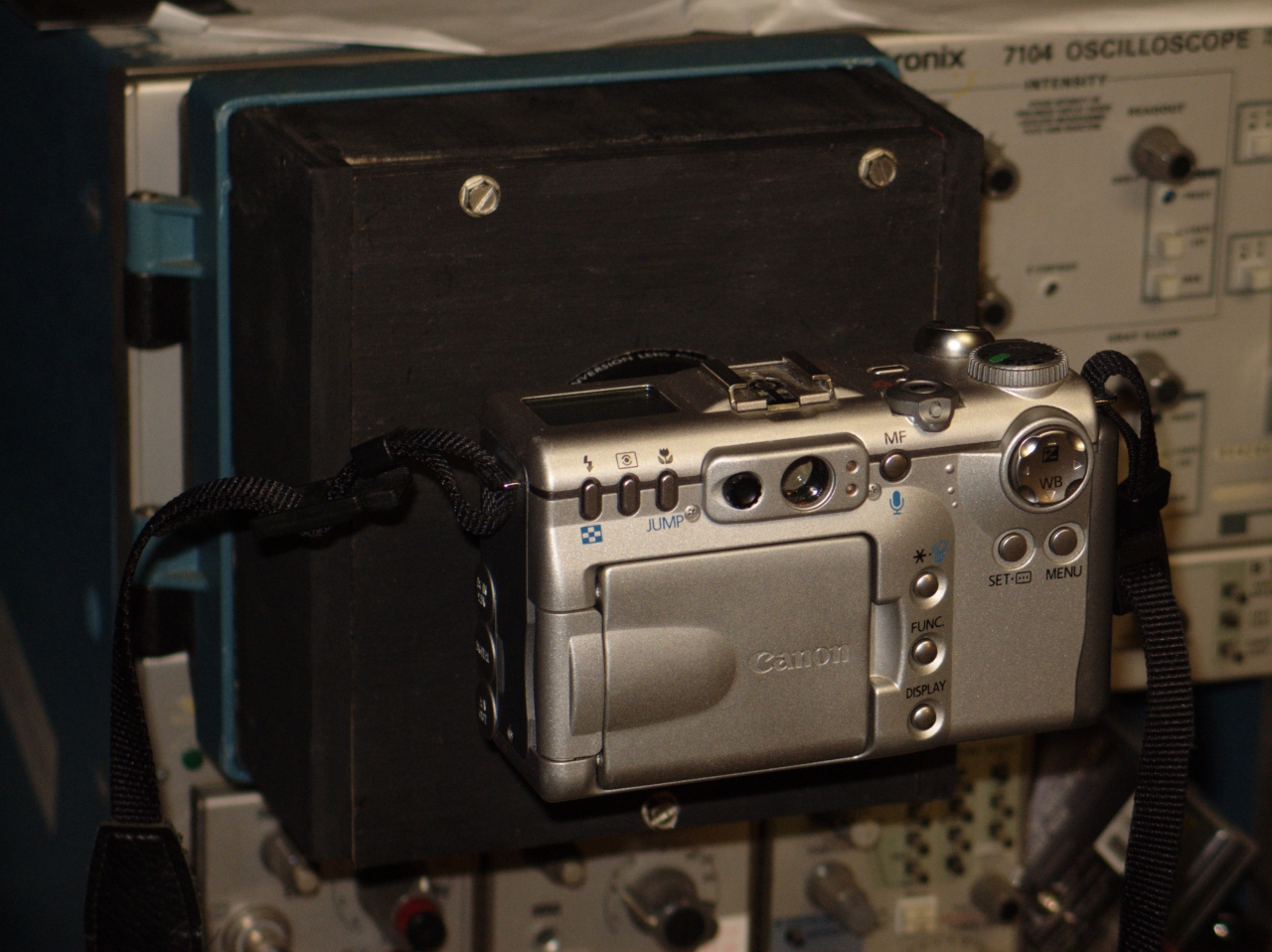
(31 December, 2008, early AM)
Here’s what the completed camera looks like:
Although I get some pincushioning with the G3, the new
setup works. End of that annoyance.
Also end of interlude; back to measurements.
(31 December, morning)
Not only did I build a new instrumentation amplifier
board, I built two of them, using what I learned from
the first to do a better job on the second. Let’s
call them 1 and 2, ignoring the original one that I
replaced. There is something very strange going on with
the amp; when I power it up (with either new board), it
shows a surprisingly large output voltage. #1 tends to
be around 15-20 mV negative, and #2 tends to be around
40-50 mV negative. This voltage takes several minutes to
decrease to something on the order of 2.3 to 6.6 mV
negative, but can increase or decrease for no obvious
reason. I have seen it as small as 0.8 mV and as large
as 7.8 or 8.1, for fairly short periods.
I tried shorting the inputs of board #1 together; the
output went to 0.1 mV or so, and stayed there. This
rather strongly suggests that the weirdness is coming
from the sensor head, not from inside the amp box.
I’m not sure whether there is much of anything I
can do about it, but I will be checking with our other
Scientech head to be sure that it isn’t just the
one device.
In addition, and this is no real surprise considering
the fact that I am putting pulses into the sensor, the
output reading varies quite rapidly. I think I will put
about 10K ohms in series with the output, inside the
amplifier box, and then put a largish capacitor across
the input of the multimeter. If I get a time-constant
that is perhaps 5 or 10 seconds, I should be able to
take readings much more easily. OTOH, it will take
much longer for the reading to go back to zero when
I stop pulsing the laser, so I may include some
provision for momentarily shorting out the capacitor.
I don’t have a diagram yet, so here is a list
of the connections to the INA2141:
Notes:
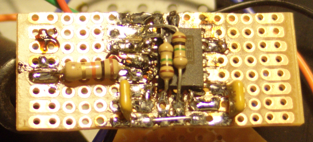
The 2nd new board may be of mild interest because the
version of the INA2141 that I’m using is a
surface-mount device, which means that the pins are at
half the spacing of the pads and holes they must connect
to (I built each amp on part of a small Radio Shack
prototyping board), and I had to finesse things a
bit. You will have to forgive my technique; I do not
have a small enough tip for my soldering iron, and some
of the work is a bit gloppy. Here is a photo of it, with
the 10K resistor (left side, about halfway up) in place:
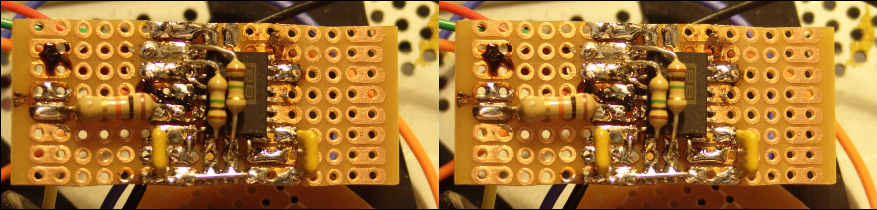
(later that afternoon)
Because it is so difficult to see what’s going on
there, I have made a pseudostereo macro shot, intended
for cross-eyed viewing. (If you try the large version
and decide that you really need more pixels, change
“17c” to “35c”.)
Note the two resistors that sit on the back of the chip
package. If you look very carefully just to the left of
the upper bulge of the one on the left, you can see pins
3 and 4 shorted to each other; they hang out in the air
in a little wishbone shape. I lucked out a bit here: pin
1 is bent a little, and goes to the second pad down from
the top; pin 2 goes to the third pad; pins 3 and 4 are
up in the air, so pin 5 goes to the fourth pad; pins 6
and 7 are shorted together, and go to the fifth pad; and
pin 8 goes to the sixth pad.
(02 January, 2009 [it feels weird to write that number!])
Last night I checked again with the new board, and
found that when I shorted out the input, I saw -1.6
mV or so on the output. It was quite stable. When I
connected the sensor head, the output again went to
>30 mV, and changed fairly rapidly. This suggests
to me that the grounding resistances I’m using,
which are 1 Megohm, could be too large. I am going to
try 1/10 of that value, to see whether it makes a
significant difference.
I made several sets of measurements and calibrations
with the first new board in place, after which I built
the second board, put that in place, and made another
set. I then did some averaging to help remove the
variations caused by the input weirdness and resultant
wobbliness of the readings.
Procedural note: the way I usually do this is to record
the initial [low] voltage reading, pulse the laser once
a second for a minute or so, and record the highest or
second-highest reading I get near the end of that
period. (These are typically only 0.1 V apart, and the
top few readings are generally similar, though there is
some variation, which may relate to the variation in the
low end readings.) Then I let the reading go down again,
and record the [new] low point, as well as the gas
pressure.
For calibration I generally take the sensor, the amp,
and the meter back to the workbench without
turning off the amp. I then use the bench power supply,
plugged into the calibration resistance, to take
readings, using the same protocol: note the initial low,
apply a small steady voltage to the calibration
resistance, note the high, measure the calibration
voltage if I haven’t already done so, turn it off,
and note the new low. For most of the later readings,
rather than attempt to match the output numbers I got
from the laser, I have just left the power supply at
232-233 mV and noted the resulting numbers, but because
I got to that input voltage by matching the laser
numbers in the first place, they were still fairly
close. The calibration resistance appears to be between
39.1 and 39.2 ohms with the lab at its current
temperature, so I used 39.15 for the last
calculation. (I used 39.0 for the first few runs,
because that was the value I got yesterday. Not that it
makes a huge difference — 0.15 ohms out of 39 is
less than half a percent.)
P (watts) = E2/R; with E at 0.232 and R at
39.15, the bench supply was putting ~1.37 mW into the
calibration resistance. This gave me, on average, about
12 mV change in the output of the amplifier, which is
roughly 114 microwatts in per millivolt out. 12 mV was
pretty close to what I was getting with the laser, so
it was convenient to run the bench supply to that level.
Earlier runs gave me higher numbers, on the order of
125 to 137 μW/mV, and I will have to do at least one
more calibration run after I put some smoothing on the
input of the multimeter, to see whether that changes
anything.
There is, btw, no real need to match the laser numbers
and the supply numbers; all you need is the number of
watts that produces 1 mV output. I matched the numbers
because it was easy to do so.
Given the above results, it appears that the sensor is
receiving about 1.4 millijoules per pulse. I seem to get
best operation around 15-17 Torr, though it is really
too early to make any firm claims about pressure
dependence. Considering the behavior of the dye cuvettes
and the fact that the pulse seems to be relatively long,
1.4 mJ seems rather low. (At 9 nsec FWHM and with a
slightly long tail, the peak power is really not much
more than 150 kW.) Still, I am only charging the main
store up to 20 kV, so I probably shouldn’t
complain too loudly. Also, I am losing a little bit of
energy in reflections from the lens surfaces, and I may
or may not be hitting the front of the sensor
cleanly. (I am thinking about adapting the back end of
the sensor to give it a mounting plate, so that I can
remove the tube from in front of it. That will let me be
quite certain that the beam is going where it needs
to. It also lets the sensor detect IR from somewhat
off-angle, which is not so desirable; I may add a
shorter tube to restrict that a little, while still
letting me check the beam delivery.)
(early afternoon, still New Year’s Eve)
With 10 K in series with the output and 680 μf across
the meter, I performed yet another set of measurements.
It was definitely easier to read the meter, and the
time-constant was short enough that I didn’t have
to worry about shorting the cap to restore the value
after running it up with the laser.
This time, I calibrated with the bench supply putting
out as close to a quarter of a volt as I could set it:
250.4 to 250.5 mV, according to the multimeter. (I
unplugged the 680 μf cap for the purpose of measuring
the supply.) Averaging things out, I appear to get very
close to 120 μW/mV, not far off from the two previous
calibration sets. (I’m still not sure about the
run where I got 137, though it may have something to do
with the variability of the readings at the low end.)
It is hard to calculate the laser’s output,
because the low-end numbers were so variable, but it
looks like I am getting just over 1.5 mJ/pulse at an
indicated pressure of 16.9 Torr. If I can figure out a
better way to measure this, I will report it. In the
meanwhile, I think it’s reasonable to conclude
that the laser is putting out something on the order of
150 kW peak, in a pulse that is about 8.5 nsec long,
FWHM.
Next: I want to put a prism into the beam. There are
several reports in the literature that indicate output
at 357.6 nm as well as the usual 337.1, and I should be
able to see two fluorescent spots on a paper target if
this laser is putting out both of those wavelengths.
(01 January, 2009, morning)
I did not see two spots, but I wonder whether the
dispersion of the prism can separate those wavelengths
enough for them to be visibly distinct in a few inches,
which was the distance to the target. I may have to try
this again with the target farther away, and perhaps
with a slit to narrow the part of the beam that hits the
prism. I did, though, use the opportunity to realign the
laser’s mirror, and now I need to re-check the
output energy. Speaking of which, I have been triggering
the laser by hand while doing that, which makes for some
irregularity even though I use a clock as a metronome,
so I just ordered a 60-rpm synchronous motor on
eBay. One cam, one microswitch, and a way to mount
everything (scrap plywood is probably my friend), and I
will have a nice even timing signal for the trigger unit.
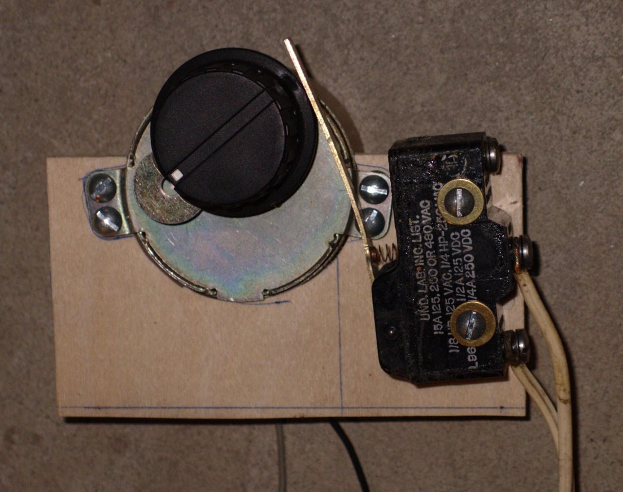
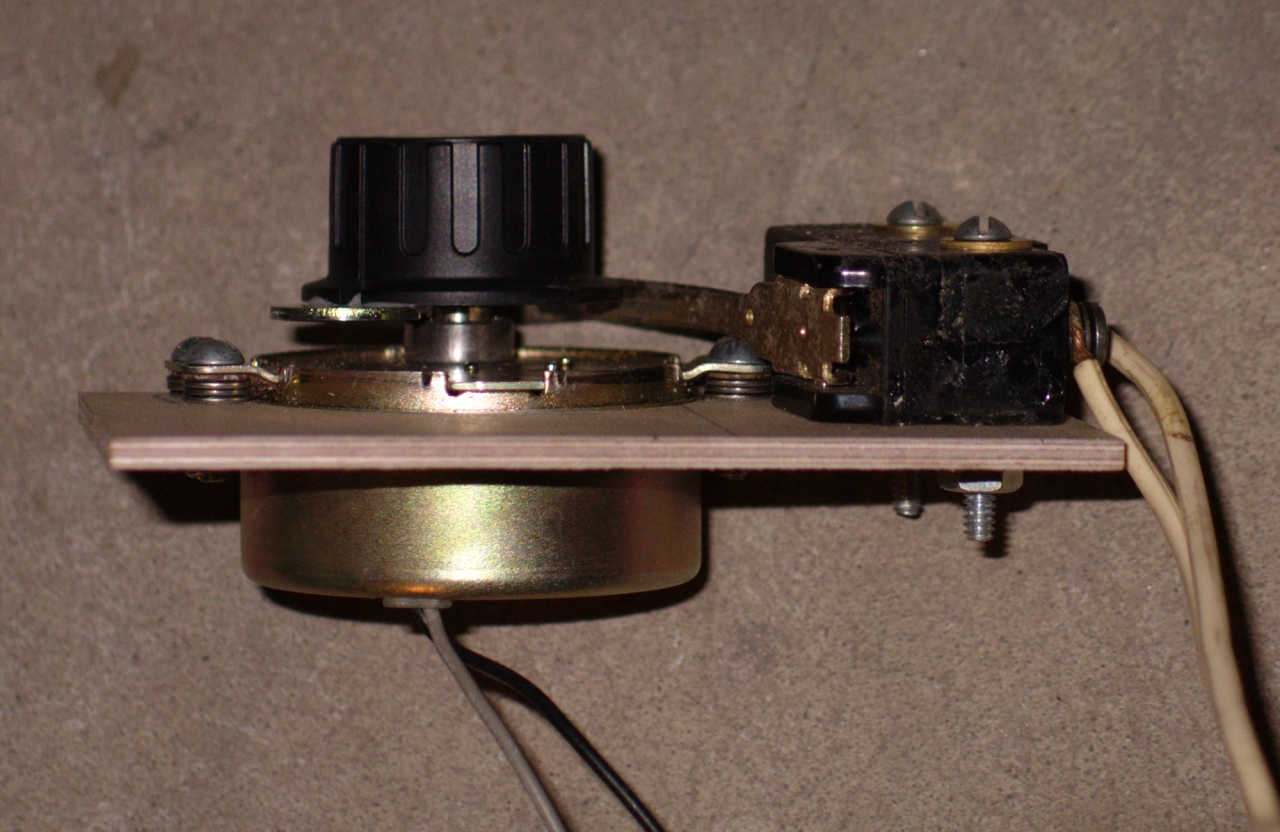
[Note, added 07 January, 2009, evening:
The motor arrived and I went to put a knob on its shaft,
to serve as a cam. The shaft, however, was too large to
fit into the knob I had on hand. I went to Radio Shack,
and found that all of their knobs were built for
¼-inch shafts, so I bought a pack of two knobs
that looked like they might work well, drilled out the
shaft hole in one of them so it fit on the shaft of the
motor, and epoxied a washer to the edge. I had to shim
up the motor a bit so the washer would catch the bar of
the microswitch, as you can see in the photos. Here is
the working unit. Sorry about the peculiar angle of the
first photo.
(I will eventually put feet on this device so it stands
up on its own.)
Having the laser pulsing once a second turns out to be
really handy, not just for taking energy measurements,
but also for making adjustments on (for example) dye
lasers I’m driving with the C5000.
End of note...]
(Evening, 04 January, 2009)
In an effort to stabilize the output of the instrumentation
amplifier, I added a 100 Kohm resistor in parallel with
each of the 1 Megohm resistors you can see in the photos
above. I would have thought that 1 M would be enough, as
the input impedance of the amp chip is something like
1012 ohms, but perhaps not...
With the new resistors in place, I set about trying to
make another set of measurements. When I turned on the
amplifier, its output went up and down about 8 times
over a period of perhaps 5 or 10 minutes, and finally
appeared to be settling near -2 mV, so I carried
everything over to the bench, whereupon it went nuts
again for a while. It eventually seemed to settle down,
this time closer to -2.4 mV (though still considerably
more variable than I would have liked), and I took data
points at several pressures. By the end of this, perhaps
as much as an hour later, it was mostly coming back to
-2.3 to -2.5 mV... mostly.
The readings were essentially consistent with what
I was getting the other night, differences as large
as ~11.5 mV at pressures around 17 Torr. I continue
to think about alternative sensors, about optimizing
the head by adding silver-conductive coatings where
I had originally planned them, and also about building
a new version of
my largest previous “doorknob” head.
(Early AM, 09 January, 2009)
Another way to get a sense of the output is to see
whether the camera can detect some difference as a
variable is changed. I ran a Rhodamine 6G dye laser
with one mirror, and definitely saw some differences
as I changed the pressure. At 3.9 Torr, I occasionally
saw weak lasing. Brightest output seemed, oddly, to
be around 14.7 Torr, though I didn’t test at
closely spaced pressures when I was taking this set
of photos, because I couldn’t see the differences
as clearly by eye. Here are some of the photos; 6 Torr,
10.4 Torr, 14.7 Torr, 23.4 Torr, and 29.8 Torr...
The peak appears to be fairly broad; I don’t see all that
much difference between 14.7 Torr and 23.4 Torr in these
photos, though a look at the entire set does suggest that the
14.7 Torr image is slightly brighter than the others.
Back to the beginning of this set
To a page about another commercial nitrogen laser we acquired surplus
To a page about a commercial TEA nitrogen laser we acquired surplus
To a pageset about some high-power nitrogen lasers
that I’ve been designing and building
To the top of the LASERs section
Email: it’s the usual “a@b.com”, where
you can replace A by my first name (jon, only 3 letters,
no “h”), and B by joss.
Phone: +1 240 604 4495.
Last modified: Fri Jun 14 23:08:37 EDT 2013
Step Three: Assembly and Initial Testing
![]()
First Light
Step Four: Measurement and Characterization
Interlude: The Oscilloscope Camera
PIN  FUNCTION  CONNECTED TO
___  ________  __________________________________________

 1    - in      1 M to Gnd, 100 pf to 2 as input bypass
 2    + in      1 M to Gnd (100 pf to 1)
 3   select     shorted to 4 for X100 amplification
 4   select      (shorted to 3)
 5    - out     Gnd
 6    + out     shorted to 7
 7    Ref        (shorted to 6)

 8     V-       negative supply; .047 μf bypass to Gnd
 9     V+       positive supply; .047 μf bypass to Gnd

10               NC
11               NC
12               NC
13               NC
14    - in       GND
15               NC
16    + in       GND
_________________________________________________________
The Joss Research Institute
19 Main St.
Laurel MD 20707-4303 USA
Contact Information: