(September, 2009, ff)
This page details the construction of an improved (I hope!) head for the nitrogen laser that is initially described on the previous page.
I need a nitrogen laser for a project or two. I have
removed the head from my most recent design in order to
rebuild it; but that is a lengthy and complex project,
so I decided to put this laser back on line first. When
I tested the head, however, I discovered that it leaked
considerably more than I wanted. In the process of
trying to find and fix the leaks, I found that some of
them were easily localized, but some were distributed
along the sidewalls. After a bit of thought and some
grumbling (after all, I started on this because I
thought it would let me accomplish a project or two
without having to do any major rebuilding) I decided to
construct a new head, using plastic walls instead of
wooden ones. (I also intend to rebuild the wooden head,
because I still think it’s a great idea, and there
is no particular reason to doubt that it is viable,
provided sufficient care is taken to leak-proof the
wood; but again, that will have to wait.)
This laser uses high voltages, and capacitors that can
store lethal amounts of energy. It puts out an invisible
ultraviolet beam that can damage your eyes and skin. It
is important to take adequate safety precautions and use
appropriate safety equipment with any laser; but it is
crucially important with lasers that involve high
voltages and/or produce invisible beams!
The original of this laser was a “Voltage
Doubler” circuit, often mistakenly called a
Blumlein. I chose the doubler circuit because it is
relatively easy to construct, and because it parallels
the circuit of the Scientific American “Amateur
Scientist” design, though I used discrete devices
(“doorknob” capacitors from an excimer
laser) rather than a piece of circuitboard. This laser,
in its second incarnation, delivered about 240 kW, which
is respectable but does not yet meet the goal of 1 MW
that I have set for the overall project. It is, however,
almost certainly enough power for the projects I have in
mind at the moment.
The circuit of the laser has not significantly changed. Here is a diagram:
(As before, I have indicated a charging inductor. That may work well for you, but a resistor could be better, and it is worth testing to find out. As it happens, I am actually using a resistor for initial testing.)
I am using the same base and spark gap that I used for the earlier versions, and most other details of this laser are also similar, except that the sidewalls are made of plastic lumber (lath or lattice strip, just over 1.5" wide and perhaps 5/16" thick), purchased at the hardware store. Although this material is less than superb, I am hoping that it will prove to be good enough. On the other hand, I do not fully trust it, and I will put a light coating of thinned epoxy on the inside faces to minimize the chances of distributed [or, for that matter, point source] leaks.
One other detail: I expect to use metal spacers (steel
rods, 5/16" square) to separate the upper sidewall from
the electrodes. These will also connect the electrodes
to the preionizer.
Because I am not using yardsticks as sidewalls, I am not limited to the length of the original heads. In the hope that it will help reduce the amount of sparking at and near the ends of the electrodes, I have decided to use electrodes that are 36" long; as a result, the new head will be 37 or 38" long. There is one possible downside to this: the capacitor array covers the middle 22.5"; any part of the channel that extends beyond the capacitors by more than an inch or two is unlikely to reach threshold, and can be thought of as “stealing” energy from the active volume of the laser. Because the electrodes are longer in this version than they were in the previous version, this extra part of the channel is also longer, and steals more energy; but at a given voltage the capacitors hold only as much energy as in the previous design. As a result, the actual active length is likely to be slightly shorter than in the previous version. I am hoping that the difference will be minimal, and will not affect the performance.
(07/08 October, 2009)
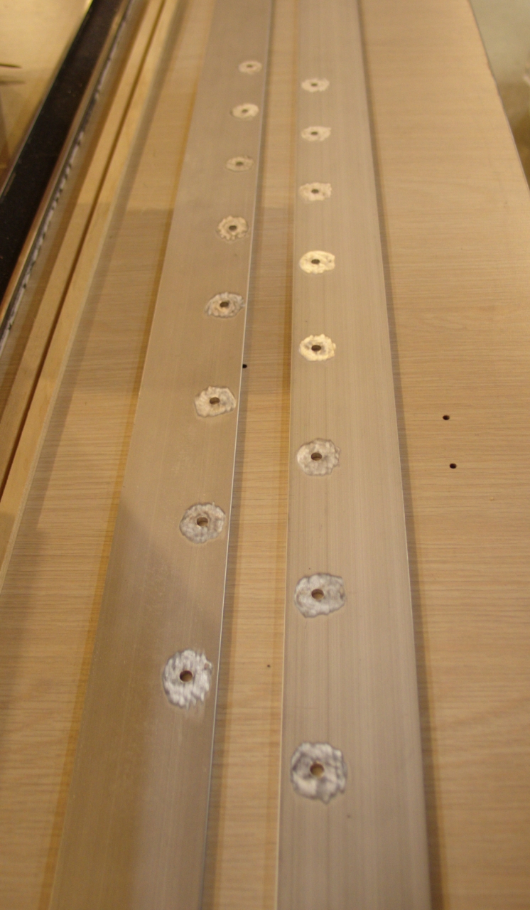
The rows of capacitors on the base are 4" apart. In each row, the capacitors are 3" apart, and the rows are staggered. (See the diagram on the previous page.) I have decided to make the channel of this new head 22mm wide, and that determines the locations of the lines along which the holes must be drilled. The staggering and spacing further determine the locations of the holes along each line. Because the electrodes face each other, they are essentially identical, and the head can, in principle, be swapped end-for-end on the base if there is any reason to do so.
Yesterday I cut the electrodes to length. This evening I marked, centerpunched, and drilled them. The next step will be to remove the anodizing from the channel edges, and curve the corners to minimize sparking and corona. After that I will remove the anodizing from the areas where the capacitors make contact, and then it will be time to assemble the head. I expect to coat each plastic sidewall with epoxy, and the preionizer layer will go onto the epoxy coating on the upper sidewall. As before, I will be using a “carpet” of silicon carbide powder, but I may try leaving an open trail for sparks, as I now have some tape that is 1/8" wide. My intention is to space the upper sidewall away from the electrodes with metal spacers, to facilitate connection from the electrodes to the preionizer.
(09 October, 2009)
I have sanded the corners of the electrodes smooth, eased the transitions into the rounding, and removed the anodizing from the channel edges. I used 220-grit sandpaper, so the surface finish resembles a “brushed” finish rather than being polished. In the past, I have made some effort to polish all of the surfaces that could contribute to corona losses, and also the active electrode faces; but it seems to me that there is good reason to want extra corona at the active faces of the electrodes, as it may contribute to preionization. Moreover, polishing the electrodes emphasizes scratches and dings, which probably isn’t helpful. I am already expecting to put some anti-corona insulation on the undersides of the electrodes (except where they contact the capacitors), and I can always put a little bit extra around the corners, so there doesn’t seem to be much urgency about achieving polish there, either. Whether I am right about these things however, remains to be seen.
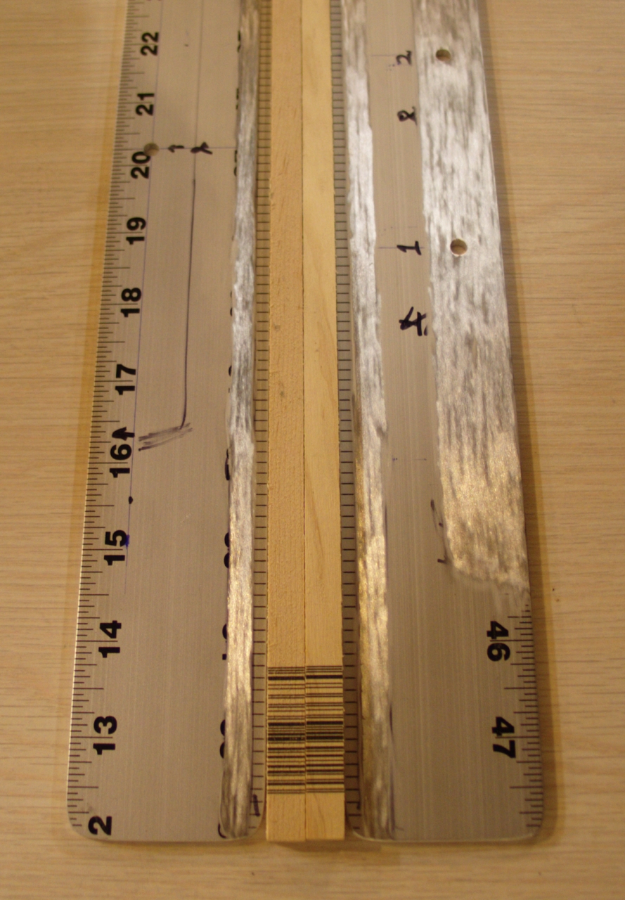
Here is an overview of some of the parts:
From the top:
Note that the upper and lower sidewalls are very nearly the same length. This will, I hope, facilitate mounting the windows on the ends of the channel. I am hoping to build adjustable mounts so that I can align (or misalign) the windows as seems appropriate.
Here is a detail of one end of an electrode, with the corresponding end of the other electrode partly visible at the bottom of the photo:
You can see the shapes of the corners, and the fact that they are not polished.
Next steps involve putting epoxy coatings on the inside faces of the sidewalls. I will use that opportunity to put the preionizer on the upper sidewall.
(11 October, 2009)
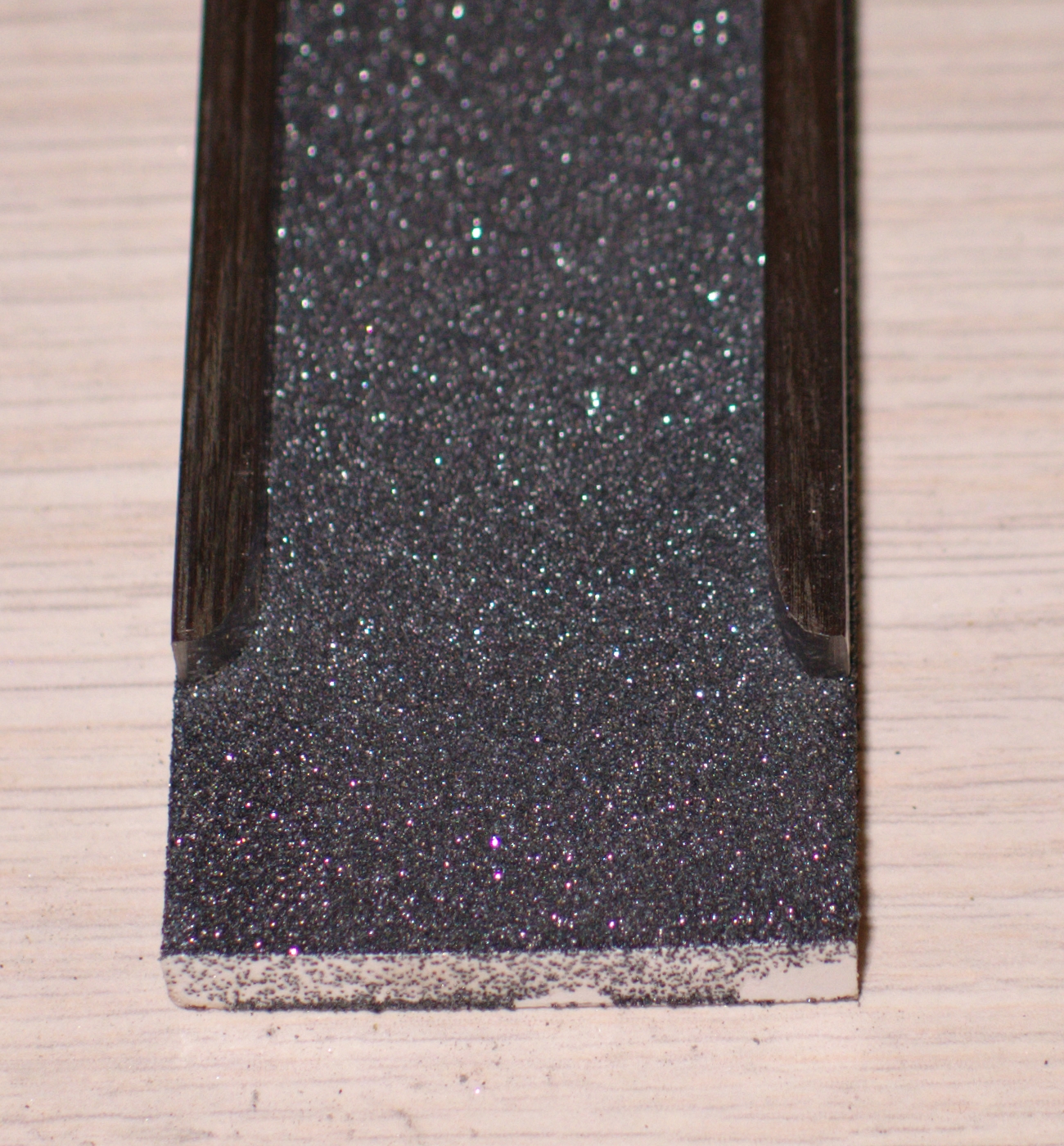
The inner faces of both sidewalls are now coated with epoxy, and the preionizer, which is a “carpet” of 100-mesh silicon carbide powder, is in place. The powder is pressed into the thin protective layer of epoxy on the inner surface of the plastic that will serve as the upper sidewall of the head. Here is a detail:
I am thinking about the fact that the ends of the steel rods are squared off. This could contribute to sparking, and I think I will round them to minimize the problem.
(14 October, 2009)
The ends are now rounded. Here is a detail of one end of the preionizer, with the rods approximately in position:
Here are the electrodes, prepared for assembly. Underside on the left (cleared areas for the capacitors to connect to); top side on the right (cleared areas for the steel rods under the preionizer, and for the brass shim that will connect the spark gap to the head).
The preionizer/lid and its steel spacers are now attached to the electrodes, and I am waiting for the epoxy to cure. Next I will attach the lower sidewall and its plastic spacers. Then I need to create the end fittings and gas/vacuum ports.
(16 October, 2009, early AM)
The lower sidewall is now attached, with aquarium caulk. I have cut the four endpieces of the head, and made the necessary holes in two of them. The other two need only a single drilled and tapped hole apiece, to hold the compression fitting that serves as gas inlet or outlet. Here is one of the endplates, showing (lefthand photo) the way I used a scroll saw to remove its middle (the beam path), and (righthand photo) approximately what it will look like when it is in place:
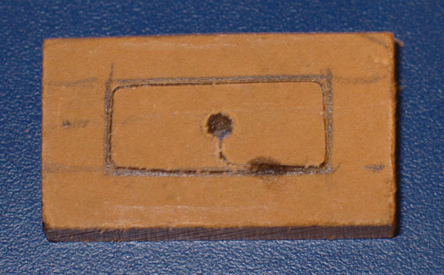
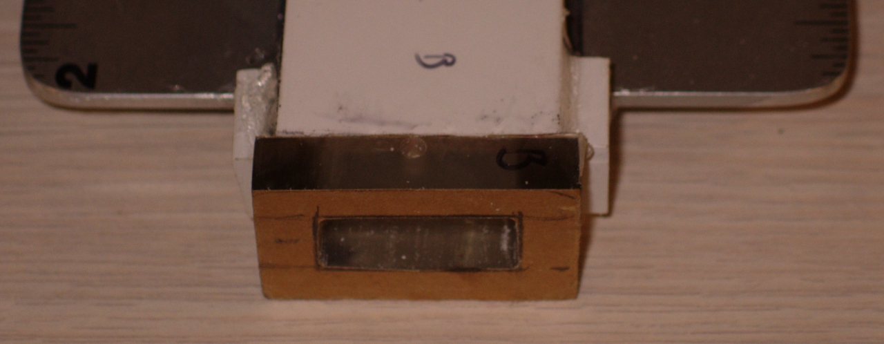
Note the small hole in the middle of the top, in the photo on the right. This is the inner part of the gas or vacuum port. The outer part is not yet fabricated. Note also the “wings” just behind the endpiece. These cover areas between the sidewalls that would otherwise be open to the air because the electrodes are shorter than the head.
(18 October, 2009, early AM)
Yesterday I attached the ends, using aquarium caulk. Then I cut a “water-white” glass microscope slide in half, and used the two pieces as the windows. These are also attached with aquarium caulk.
Last night I fabricated the gas ports and installed the
compression fittings. This involved cutting the two
pieces of 3/8-inch-thick polycarbonate to size, and drilling
and tapping a hole in each of them.
A word about drilling holes: after a number of less than
optimal experiences, I have concluded that the standard
advice (drill a very small pilot hole, then enlarge the
hole, but never go up more than a few drill sizes at a
time) is entirely accurate. I actually went up by 3
sizes at a time with the polycarbonate, but that’s
because it is rather soft. It is also advisable to hold
things in a vise, rather than in your hands. When you
are trying to tap a hole, and you are rotating the
drillpress by hand because the motor would be far too
fast, it is extremely helpful to have the workpiece
held firmly and securely. It is also extremely helpful
to use the drillpress for this, as otherwise the first
few threads are likely to be lousy.
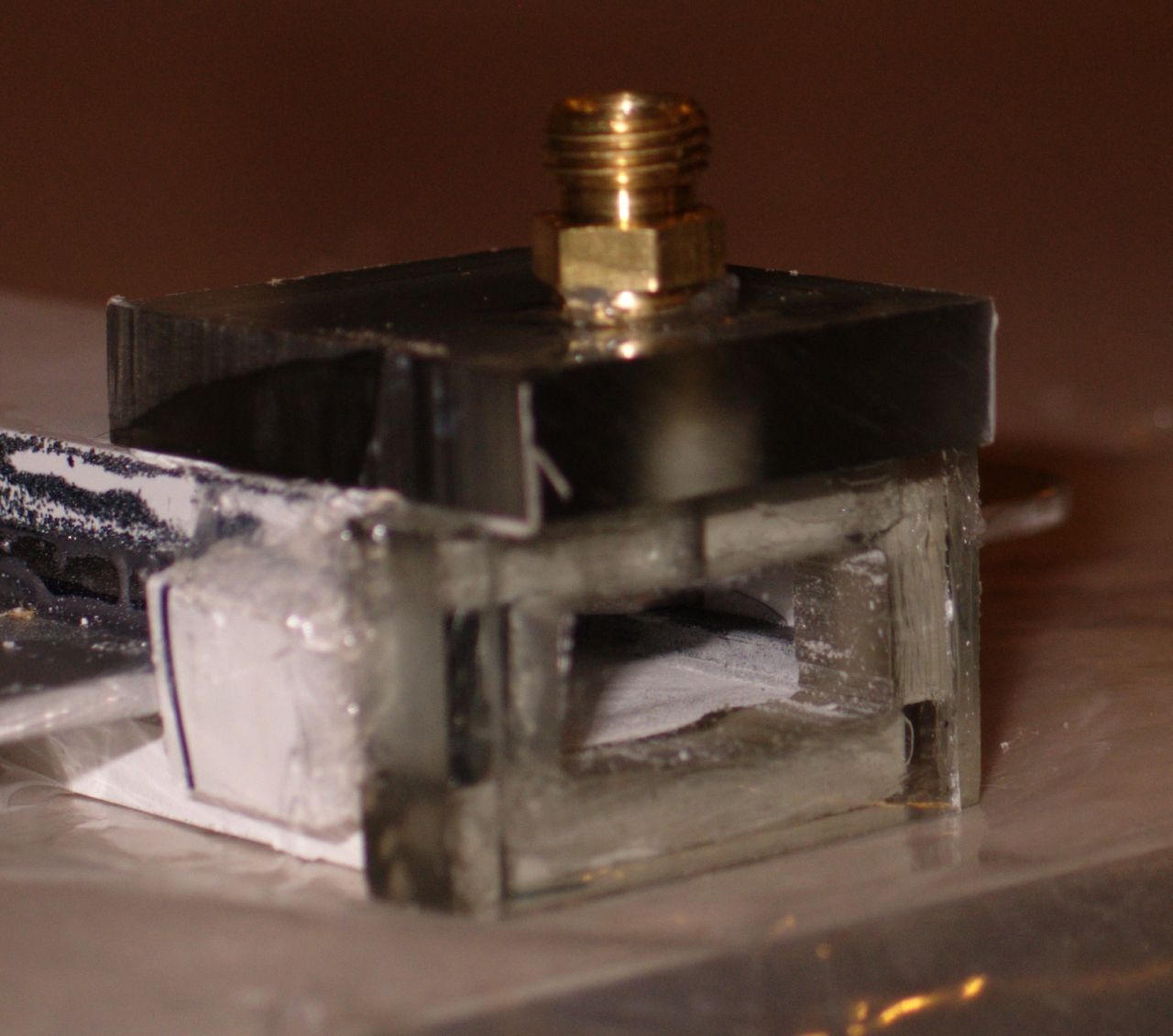
After the port plates were completed I used aquarium caulk to attach them. Here is a view of one of the ends of the completed head:
(28 September, 2009)
Even a relatively small leak will compromise the performance of a nitrogen laser, so being able to find and repair leaks is crucial to obtaining optimum performance. When the leaks are really large, you can see or hear them. I find that a hands-free with a very small microphone helps, because its “ear” is a lot smaller than mine. (Using a handy application on my iPhone that generates a waterfall sonogram, I look for broadband hissing with a large high-frequency component.)
As the leaks get smaller, it becomes more difficult to find them by ear, and you need to move to the next level. A good vacuum gauge is handy at this point. It tells you approximately how fast air is getting into the head or other parts of the system, and if you can put your thumb on top of a leak you may be able to see the pressure in the head change.
One method I find extremely useful is to dip the head, or one end of it, in water and blow into the hose at one end while putting your thumb over the hose at the other end; wherever you see bubbles, there is a leak. Using a trough that I built for the purpose, I was able to bring the head of this laser to about 2 Torr by this method.
It is also possible to apply a dilute soap or detergent solution to the outside of the head instead of actually dipping it in water. I worry about this method, because you have to be very certain to get all of the soap off before you attempt to apply any sealant, but it has been used successfully by lots of people.
Even if you can pump your laser head down to a Torr or so, it is easy to show that there are leaks: valve off the nitrogen supply, evacuate the head, valve off the vacuum pump, and watch your vacuum gauge. It should take at least 15 seconds to go from 1 Torr to 2, and even that indicates a lot of leakage. (If you do not have an electronic gauge, you can still do this with a mechanical gauge: it should take many minutes to go from its low-end reading, which should be as low as it can display, to even as much as a few inches of Hg.) Remember, btw, that some of the leaks may not be in the head. It is a very good idea to make sure that the rest of the system is clean before you add the head to the equation.
If there is a distributed leak or if there are lots and lots of tiny leaks, you have a real problem on your hands. (It is quite difficult to discover the location of something that is nonlocal...) If your laser head just won’t get down to pressure, and you are reasonably sure that the issue is not elsewhere in the vacuum system, you may want to think about rebuilding the head.
Aside from the issue of distributed leaks, it should be possible to get a nitrogen laser head sufficiently tight with these methods that you can pump it down to 1 Torr or better. That, frankly, is good enough for most nitrogen lasers. There are times, however, when 1 Torr isn’t even a real vacuum...
As the leaks get still smaller, they begin to shriek at about 40 kHz. At this point, if you really need to proceed further, you can switch to an ultrasonic translator (“ultrasonic sniffer”) if you have or can get (or construct) one.
A leak that you can’t find with any of these
methods is either a virtual leak (something in the
system that is releasing gas), distributed over a broad
area (think about rebuilding), or not worth worrying
about.
(back to 18 October, 2009, early AM)
This evening I ran a bead of RTV along each edge of the lower sidewall, as a prophylactic measure. (I have had leaks occur in similar areas in the past.) When that had started to harden, I began vacuum testing. There are leaks at both ends of the head, which is expectable at this stage. I have run RTV over the obvious locations, and I will resume testing tomorrow, after it has had time to harden.
(19 October, 2009, evening)
After applying RTV to all of the obvious places, I found that I still couldn’t pump the head down, so I dipped the ends of the head into a bucket of water while blowing gently into a hose attached to one of the ports. (The other port is blocked.) As I discuss on the previous page, this is a very pleasant way to find leaks of modest size. It disclosed a leak at one end, and various leaks along the attachments of the upper sidewall. It obviously needed to be sealed, so I ran a bead of RTV down each edge.
That RTV has now partially cured, and is stiff enough to test; as of a few minutes ago I can pump the head down to less than 8 Torr.
(20 October, 2009, early afternoon)
I dipped the head in a trough of water, and found only one more leak, at a corner of one of the end fittings. After I put some RTV on that area, I applied a very gentle vacuum, and then valved it off. It took about 15 seconds to get from 734.0 Torr to 734.1 Torr, which I take to be a good sign.
I had to coat the underside of the previous head with HV insulation to prevent flashovers, and there is every reason to expect the same issue with this one, so I turned it upside down and coated the exposed parts of the electrodes (except, of course for the places where the electrodes will be attached to the capacitors). I am using a different type of insulation this time, something that is rated to handle something like 4,000 Volts per mil thickness (over 100 V per micron). I was particularly careful to coat the corners to minimize corona losses in addition to fighting flashovers, and will probably give them a second coat later on.
(20 October, 2009, late evening)
Having dipped the head in the trough again, found more issues, and applied some RTV, I was able to take the head down to 2.2 Torr this evening. That is not quite as good as I’d like, so I did one more dip, found a small stream of bubbles, and applied RTV to it. It is far from perfect, but I think it may be good enough for initial testing, so I will fabricate the piece of brass shim that connects the cathode to the spark gap and give it a try, probably tomorrow.
(21 October, 2009, early afternoon)
If I open the vacuum valve fairly wide, I can get the head down to 1.6 Torr. I am fabricating a piece of brass shim stock to connect one row of capacitors to the spark gap, and I will probably test the laser within 48 hours. I do not want to stress the vacuum pump or use up large amounts of nitrogen, so I will probably tolerate more leakage than I really want, at least initially; but at least I will have a temporary laser for the projects that I have in mind.
(22 October, 2009, afternoon)
File under “Measure twice, cut once” — I actually did measure twice; but I didn’t check the diagram, and I didn’t attend to the little uneasy feeling I had. As I mention above, the two lines of capacitors are 4" apart; but when I measured, for some reason I got 3&7/8". As a result, I am now [painfully] enlarging the holes for the screws that attach the electrodes to the doorknob capacitors. It’s nearly done, though, and with some luck I will be able to test the laser either tonight or tomorrow.
(Early evening)
The head is now mounted very loosely on the capacitors,
and I have run a vacuum test. With the needle valve open
a modest amount the head pumps down to less than 4 Torr,
which is acceptable for initial testing but probably not
for much more than that. Later, I will put some more
time and effort into cleaning it up; I want it to pump
down to better than 2 Torr, even if the needle valve is
open only a little bit.
(23 October, 2009, early AM)
This device is a laser. It actually ran during the
initial test session, which is not common (at least, for
me). It seems to want 60-70 Torr pressure, even at 20
kV, which is somewhat higher than I had expected. I do
not yet know what the optimum pressure will be as I
bring the voltage up to 30 kV, but there is some work to
be done first. (I’m having some trouble with the
spark gap, which may be nearing the end of its lifetime,
and there are a few other issues that want to be cleaned
up.)
(23 October, 2009, late evening)
I have brought up my larger power supply, and I’m
running the laser at something in excess of 20 kV. It is
behaving much better at the higher voltage, and is
easily powerful enough to pump common dyes. It seems to
work reasonably well over a broad range of pressures,
from a low of 45 or 50 Torr to a high of over 135 Torr.
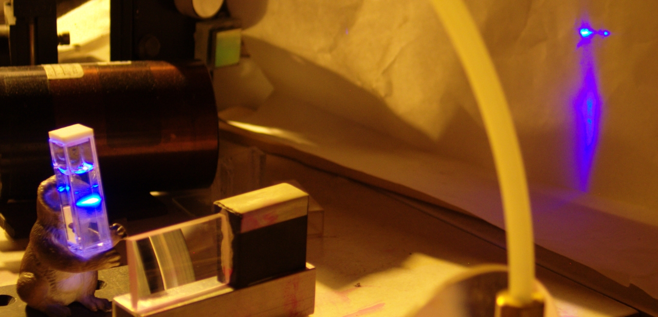
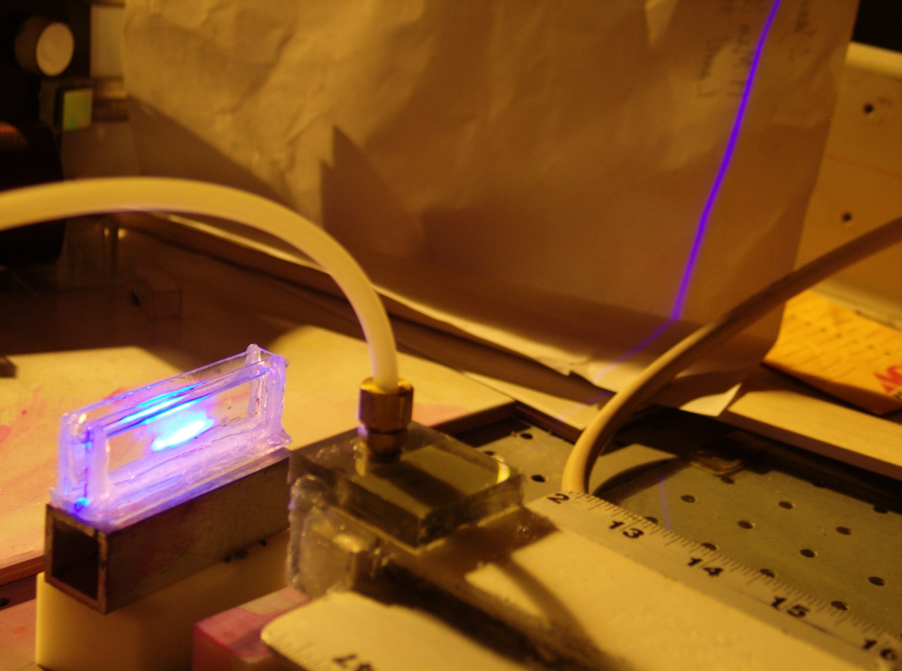
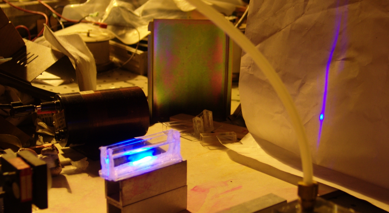
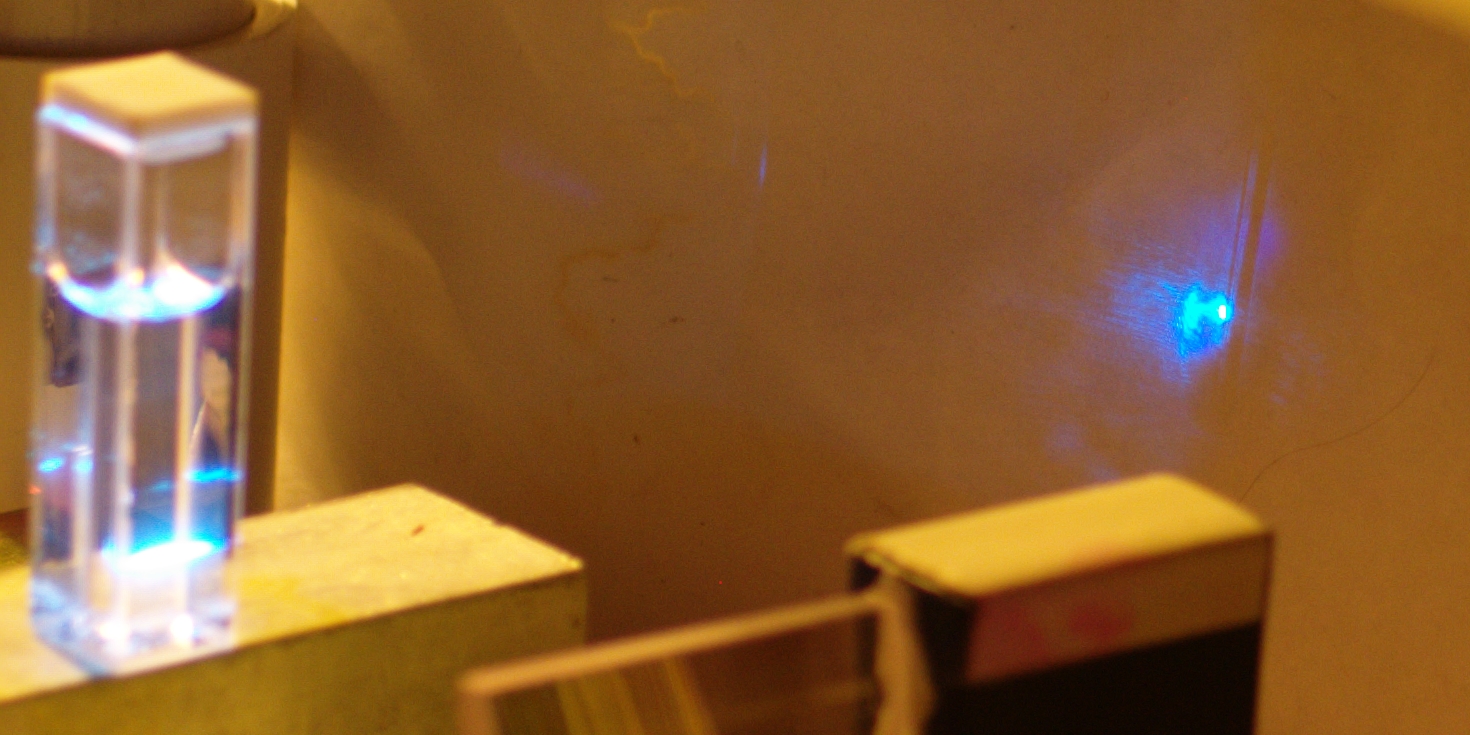
In this photo, it is pumping Dharma Trading Company
“Optic Whitener”, which I usually refer to
as DTC:
[Two small drops of DTC went into a little less than 3
cc of 99+% pure isopropyl alcohol; I added 7 or 8 drops
of distilled water to clear the solution — DTC is
not readily soluble in pure isopropanol. The beam from
the nitrogen laser is being focused by a fused silica
plano-convex lens and a cylindrical lens (probably made
of BK-7), both of which are at least partly visible in
the photo. The walls of the cuvette are serving as
low-reflectance mirrors for the dye solution. The
solution, btw, was still slightly turbid, and was also
slightly contaminated with R6G. The gain of DTC is high
enough to overcome both of these issues. The spot on
the paper target, however, is larger than it would be
if the dye solution weren’t a bit cloudy.]
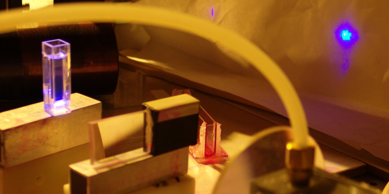
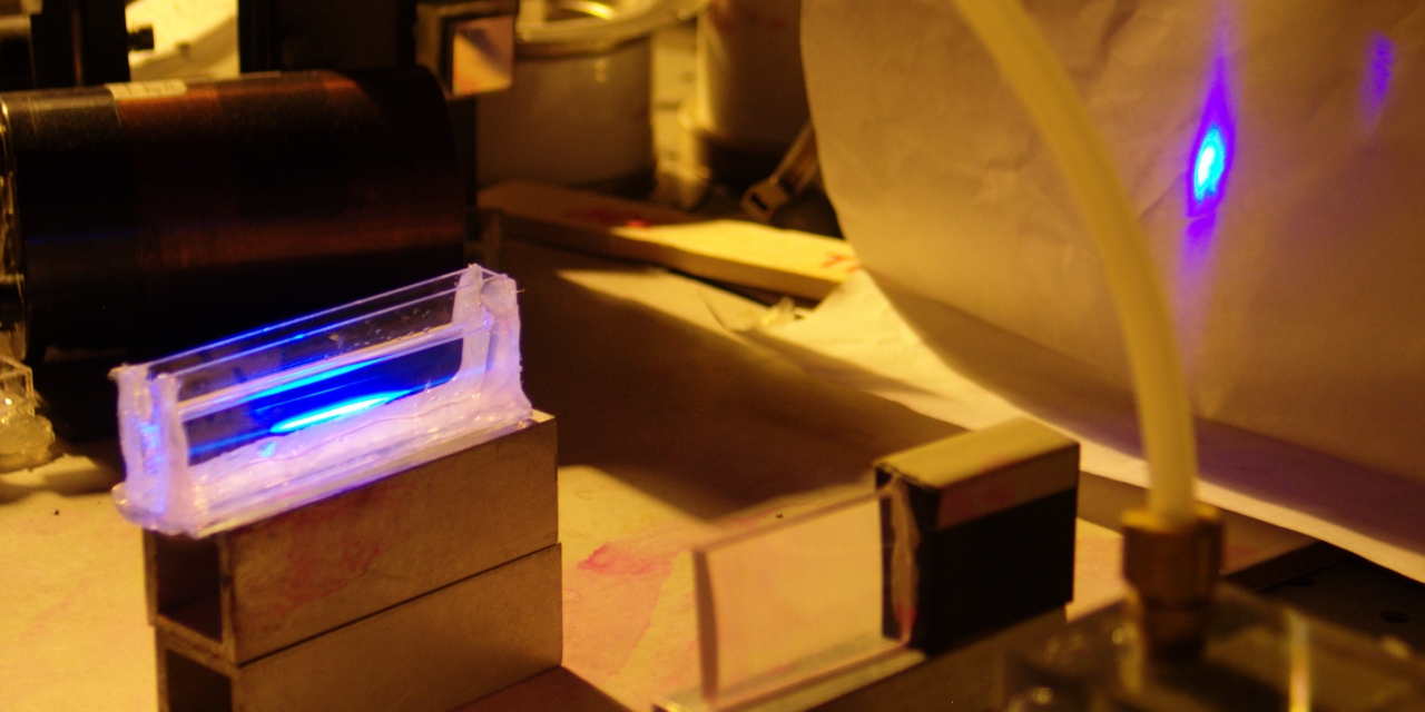
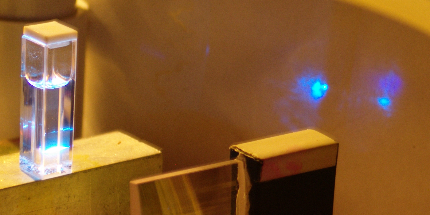
Here is another photo, illustrating that effect and a
related one. [For this photo I made fresh dye solution:
2 small drops of DTC in about 2.5 cc of ordinary 70%
isopropyl rubbing alcohol from the drugstore. The
pressure in the head was close to 100 Torr.]
Notice the dye laser output on the paper, on the right
side. You can see three distinct spots. The lower one,
which is tall and somewhat cloudy, is the result of
superfluorescence. The cuvette is tilted and
there are no external mirrors, so the beam is defined by
the shape, size, and orientation of the excited region,
which you can see (to some extent — it’s
overexposed) on the front of the cuvette. This is,
obviously, quite similar to the way a nitrogen laser
works when there is no mirror at either end; but most
nitrogen lasers are a lot longer than they are wide, so
they put out beams that are collimated better than what
you see from the dye here. (If I used a wider cuvette
and focused the beam to a longer stripe, I would get
a smaller spot on the paper. At some point I may do
that, and if so I will provide a photo for comparison.)
In the upper two spots, the dye is using the walls of
the cuvette as mirrors. They are above the cloudy spot
because the cuvette is tilted. You will notice that
these spots are smaller, more sharply defined, and
brighter — collimation improves quite a bit with
even one mirror, and here we have two. The smaller spot,
btw, seems to be from a secondary reflection.
In case you had any doubts, I will point out that the
dye is creating all of the spots simultaneously, lasing
with and without mirrors at the same time; the photo is
a single exposure.
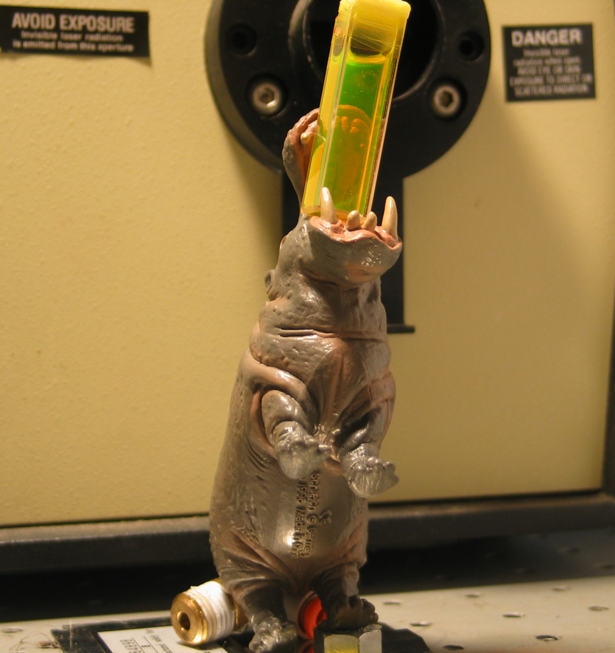
Wally, our new cuvette holder, duked it out with our
regular cuvette holder,
Mr. Hip, for the privilege of making his debut here.
Wally is a bit unstable, and we are going to have to
do a bit of work on him, but I expect to see more of him
in the future.
(24 October, 2009, afternoon)
I removed the head from the base, and dipped it yet
again into the water trough. This time I found 3 more
leaks. (Where do they come from?!) Fortunately, things
seem to be fairly stable now: after I rubbed RTV over
the 3 places and pulled a very gentle vacuum, it took
about 20 minutes for the head to go from 717.8 Torr to
720.6 Torr; 10 minutes later it was still at only 720.7
Torr. After the RTV has properly hardened, I will see
how well it pumps down.
(24 October, 2009, evening)
It pumps down fairly well. In fact, the “Wally”
photo, above, was taken later in the afternoon. Here is
another photo, this time something I don’t get to
see very often. In fact, I don’t think any of my
previous nitrogen lasers has been able to do this:
What you see here is the unfocused output of the
laser, pumping DTC to superfluorescence. The cuvette is
fairly large, so I used 9 or 10 little drops of DTC, in
70% isopropanol from the drugstore. I kept stirring and
then looking through the cuvette the long way, expecting
to get a nice crisp image, but seeing lots of schlieren
instead. I think it took 3 solid minutes before the
solution cleared. If you use DTC, please bear this in
mind. Insufficient stirring “will fail to provide
satisfaction,” as the British would have said in
an earlier era.
The battery in the camera was running low, so I didn’t
even get a chance to optimize the pressure; I think it was
about 143 Torr, much higher than I wanted. I’m
recharging the battery, but I think the point is made.
This appears to be quite a decent laser.
(24 October, 2009, late evening)
I did take another photo, with the gas pressure at
just about 100 Torr:
Shortly after I took this photo I was tweaking the
mirror of the nitrogen laser to see whether I could
improve the output of the dye, and I heard a small
“TIK” sound, not very different from the
sound the laser makes when I fire it. Unfortunately, the
sound was not a good one; the laser no longer runs, and
I suspect that one of the capacitors has crapped out. If
that isn’t the problem then it is likely to be
rather more serious, and will probably be significantly
harder to repair; I have my fingers crossed.
(25 October, 2009, late evening, and 26 October, 2009,
early morning)
Very fortunately, the laser was not the problem, and the
fix was easier than I expected. I have repaired the
power supply, which had developed some kind of rather
mysterious short-circuit to ground, and the laser is up
and running again. Let’s take another look at the
“nofocus” thing.
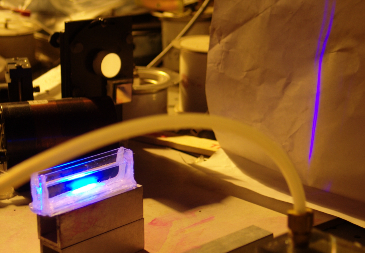
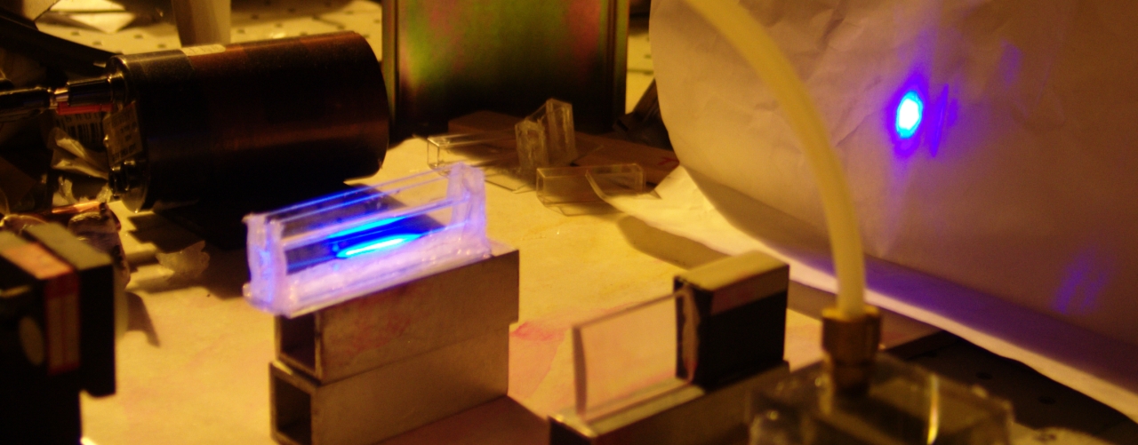
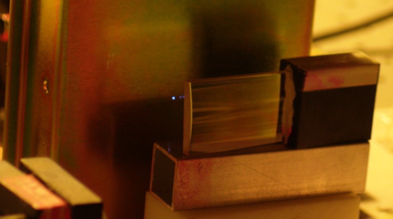
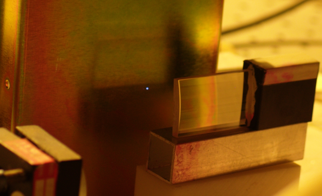
Here are two photos. In the first, I have a cylindrical
lens focusing the beam from the nitrogen laser into the
cuvette. Even without mirrors, the pumped stripe is
fairly long and narrow, so the beam is reasonably well
collimated. In the second, taken moments later, I have
removed the lens, and the unfocused beam is pumping the
dye; the broad pumped stripe does not produce a
well-collimated beam, ...but the dye is still clearly
lasing.
This is freshly mixed dye solution, about the same
proportions as in the photo from yesterday. The gas
pressure was about 99 Torr (it bounces up and down a
little, every time I fire the laser), and the voltage
was probably 29 or 30 kV. (Something is not right with
my big electrostatic voltmeter, so I don’t have a
more exact reading right now.)
Now let’s look at what happens when you provide
some feedback. Here are essentially the same two photos,
except that I have now added one mirror. (You can
partly see the mount holding it, at the left edge.)
Note the totally blown-out center of the spot in the
picture on the left, and the bright spot along the
vertical line in the picture on the right. As I
mentioned above, adding some feedback definitely
tightens things up! This is one of the reasons why it
is a good idea to put a mirror at one end of a nitrogen
laser; sometimes it more than doubles the output, and it
almost always helps.
(27 October, 2009, early AM)
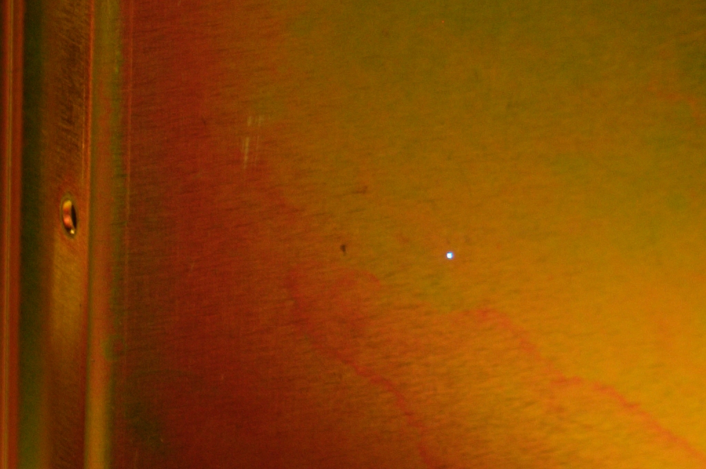
There are various informal ways of estimating the
output power of a nitrogen laser. If the focused
beam will run a small dye laser, then you probably
have at least 25 to 50 kW. If you can make sparks
by focusing the beam onto a metal surface, you
probably have more than 150 kW.
Sorry those are slightly out of focus, but the one
on the left shows several sparks, which is significant;
adding the cylindrical lens results in a tight line.
Here is one without the cylindrical lens, but in better
focus:
These are not very large sparks, but you aren’t
going to get a big spark with a few millijoules of
light.
If the unfocused beam will pump a small dye laser,
the chances are pretty good that you have more than
200 kW, but this measure is sensitive to quite a
few variables, so it is not very reliable.
If you can measure the pulsewidth and the pulse energy,
you will (obviously) have a much better sense of the
power. It is not too difficult to measure the energy
in the pulse; I have discussed at least one method
one one or another of the pages in this set. It is,
however, not so easy to measure the pulsewidth. You
will need a fairly fast oscilloscope (several hundred
MHz bandwidth or better), and an equally fast detector.
If the detector is not sensitive at 337 nm, you will
also need a way to shift the wavelength, and that must
be equally fast — you aren't going to see an
8-nsec pulse if you use a dye with 43 nsec fluorescence
lifetime as a wavelength shifter. Even Rhodamine 6G
and other common laser dyes are not really fast enough.
(I am working on pulsewidth and pulse energy measurements
for this laser. Currently having some trouble with
instrumentation, which is extremely frustrating.)
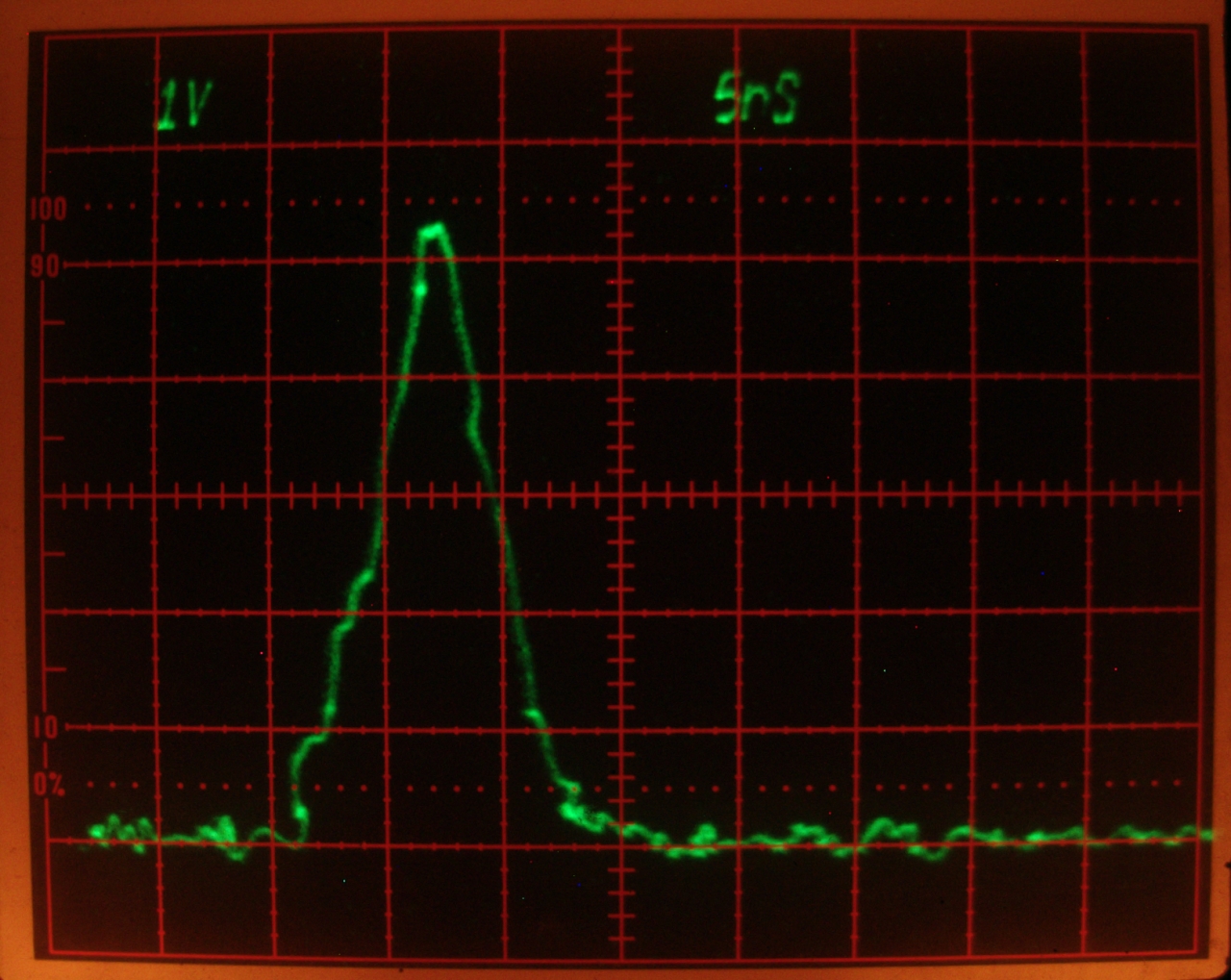
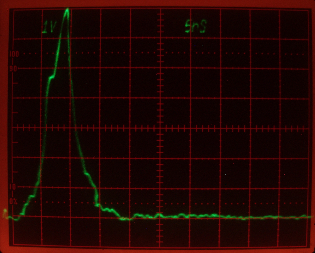
(29 October, 2009, late evening)
I built an enclosure for the batteries that power my
fast photodiode, and although I am still having some EMP
issues, as you can see by the small wiggles in this
photo, I do have at least some notion of the pulsewidth,
which appears in most of the photos to be between 5.5
and 6.5 nsec:
(This photo was taken at an indicated pressure of 89.2
or possibly 89.3 Torr. The trace is fairly typical. It
is more or less triangular, rather than sinusoidal; I
doubt that this is particularly unusual.)
We can, I think, reasonably call it 6 nsec, at least for
now. The next thing is to get a pulse energy measurement.
There is a problem with my instrumentation amplifier,
and I will be working on it as time permits. Once I have
completed the energy measurement, I may consider
switching to 2-nf capacitors, to see what effect that
change has on the performance.
(30 October, 2009, late evening)
If you are fortunate enough to have a disused Peltier
(thermoelectric) cooler, such as people use for cooling
computer chips, you can measure the pulse energy fairly
easily. You will have to glue a thin copper
heat-spreader plate to the front of the TEC, then glue a
few turns of resistance wire to the front of the
heat-spreader (insulated, so it doesn’t short
out), and then paint it flat black. (The black spray
paint that is intended for gas grills is apparently a
relatively good choice.) It helps to mount the TEC at
the end of a fairly long tube, to minimize the amount of
roomlight that reaches it. Remember, it doesn't know or
care where the energy is coming from! It also helps to
mount the back side of the TEC to a largish block of
metal, so that it tends to stay at a given temperature
even though you are putting some heat into the front
side.
When you establish a temperature difference across a
TEC, it puts out a voltage. The amount of voltage
depends on the temperature difference. If you only put a
very small amount of power into the front of the TEC,
you get very little voltage out. I use one side of an
INA2141 instrumentation amplifier chip to multiply the
signal voltage by 100. The amplifier makes it possible
to see the voltage change. I use an oscilloscope to
watch this, because it is easy to get a sense of the
voltage on the screen. (It is much harder to try to read
a constantly changing number on a digital voltmeter.) I
also use a timer motor and a microswitch to trigger the
laser once a second. This makes it much easier to decide
what the energy of each pulse is, once you have measured
the power level. Here is the method I use:
The calibration resistances on the two commercial heads
that I have here are close to 40 ohms each. Here is an
example calculation: say I find that it takes 200 mV
from the power supply to get approximately the same
scope reading as I got from the laser. The average
power, then, is .2 x .2, or .04, divided by 40, which is
.001 watt, or 1 milliwatt. Because the laser is being
pulsed once a second, this means that each pulse is
about 1 millijoule.
When you have the pulse energy and the pulsewidth,
it is quite easy to calculate the average power
during the pulse, and fairly easy to figure out
roughly what the peak power is.
(26 November, 2009)
This afternoon, I swapped out the 900-pf capacitors and
replaced them with 2-nf capacitors. My hope was that
this would give me higher peak power and longer
pulses. I have not yet been able to align the mirror,
but an early look at the pulsewidth is encouraging, if
only in the sense that the pulse now appears to have a
much flatter top than it did before. The pulsewidth,
though, is only about 6.5 nsec at half amplitude, not
very much longer than it was earlier.
I think that was at a little less than 60 Torr, but
I’m not really sure. I will be checking this
when I have time and energy.
In the meanwhile, I now have a sensor head for the
Molectron JD2000 Joulemeter. Unfortunately, the head is
extremely sensitive, and the full-on beam would damage
it. I need to make an optical attenuator that subtracts
about 99% of the beam, after which I will be able to
make a measurement. I have already measured up to about
28.5 μjoules from a tuned dye laser that was being
driven by this nitrogen laser, before I swapped out the
capacitors.
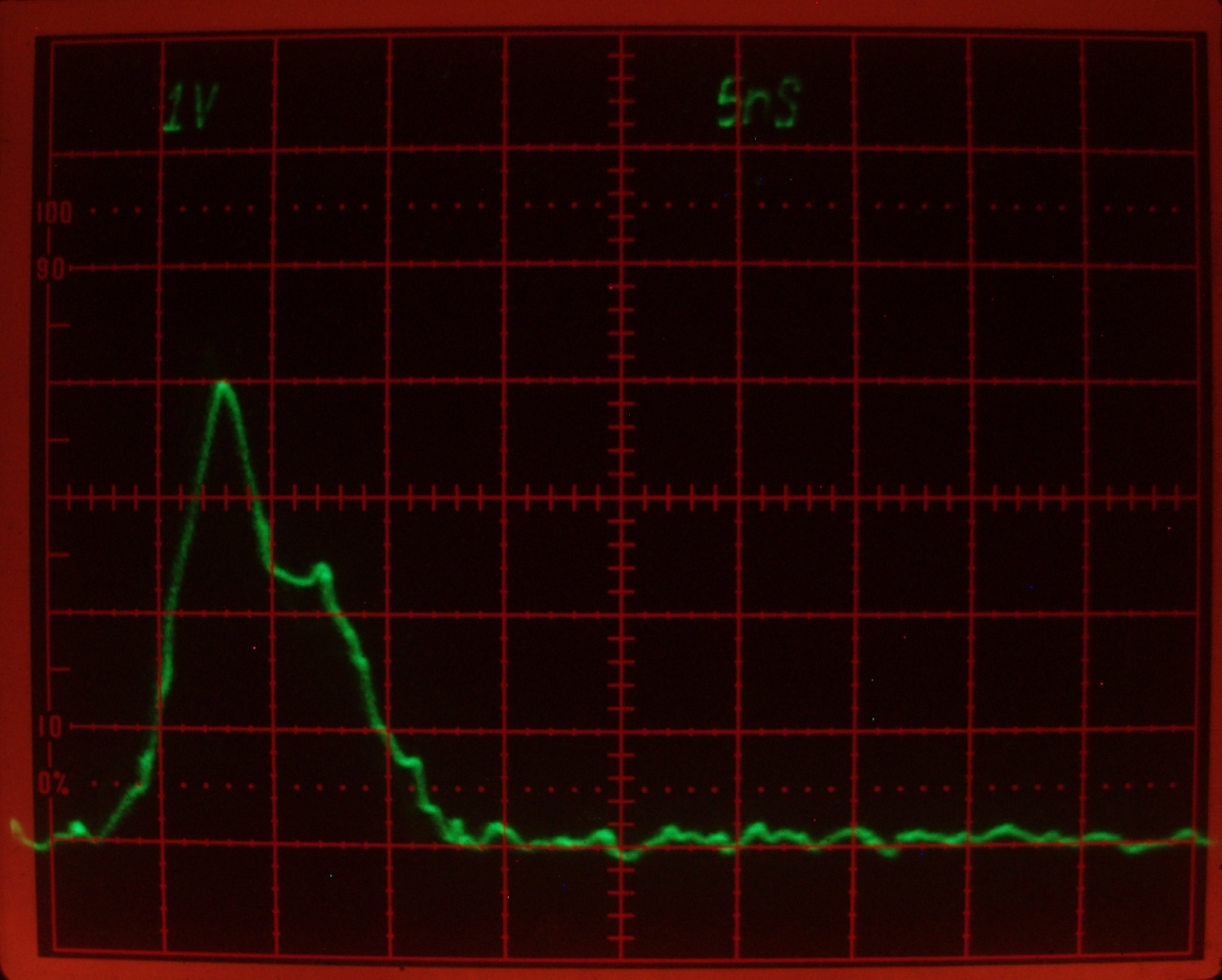
(later that evening)
I have aligned the mirror, and decreased the voltage
a little. I think this trace was taken with about 85
Torr of nitrogen in the laser head, and that may be
part of the reason why the peak appears different.
[I had to enhance the brightness of parts of the trace,
because they were almost invisible.]
The pulsewidth is still only about 6.5 nsec, but the
pulse is more “peaky”. I do not know whether
the absolute amplitude is different; it is important to
understand that the heights of the scope traces are
entirely arbitrary, and have nothing to do with the
actual power. It is just 1 volt per box on the screen,
regardless of what is producing the voltage.
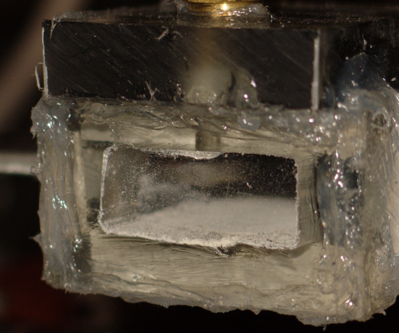
(01 December, 2009, evening)
I thought there might be some dirt on the rear window,
so I checked it. Found only a few tiny dots of dust.
The front window, however, looked like this:
I have replaced the window and cleaned the end of the
head a little, and I’m waiting for the RTV to
cure. My one worry is that the filth on the window is
plastic from the sidewalls (probably the lower one), and
was generated during normal operation. If that’s
the case I will be obliged to do this again and again,
not my idea of a good time. We’ll just have to see.
(04 December, 2009, early am)
A few days ago I found an interesting article in the
Soviet Journal of Quantum Electronics. It was about a
charge-transfer nitrogen laser design that used a fused
silica flat as an output coupler, and was deliberately
operated at low energy density in the discharge to avoid
superluminescence. That seems counterproductive to me,
but the laser delivered 4.5 millijoules in a pulse that
was 12 nsec FWHM, and had peak power of about 400 kW,
which is quite respectable. I found that intriguing, and
I decided to see what would happen if I put an output
coupler on my laser. Instead of fused silica, however, I
used alumina, which has somewhat higher reflectance.
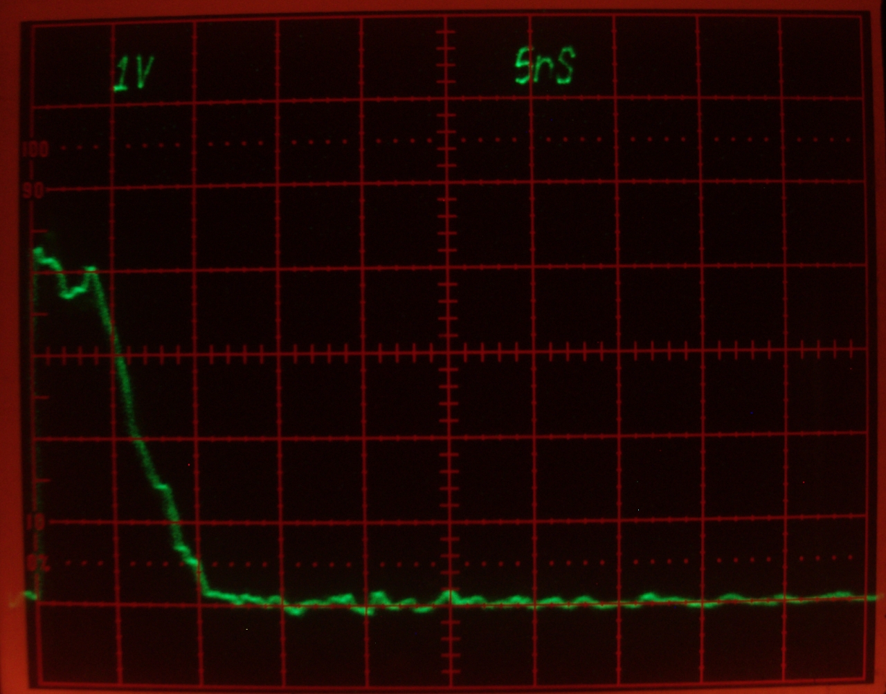
What I find is that at relatively high pressures the
pulsewidth is largely unaffected; here is ~95 Torr:
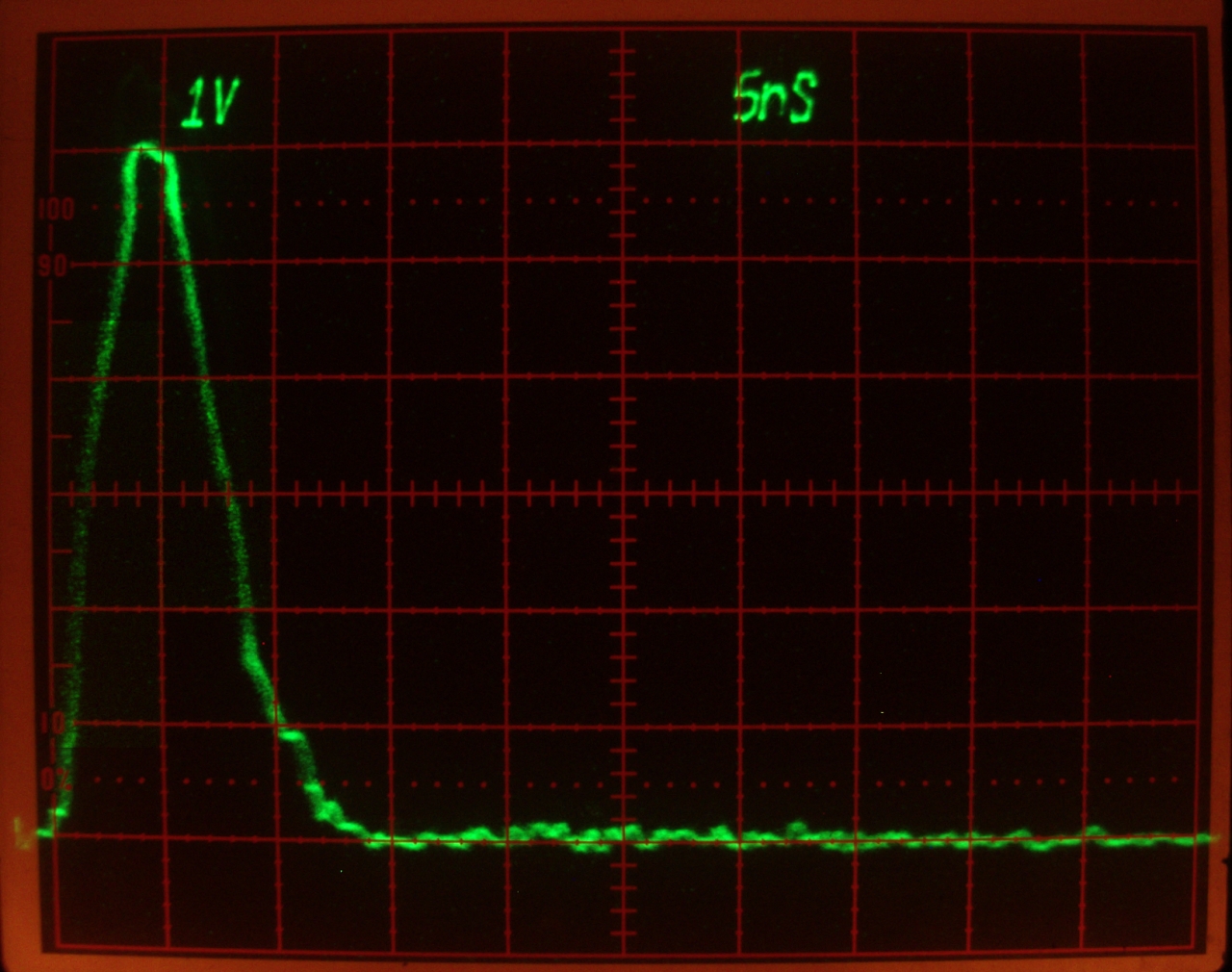
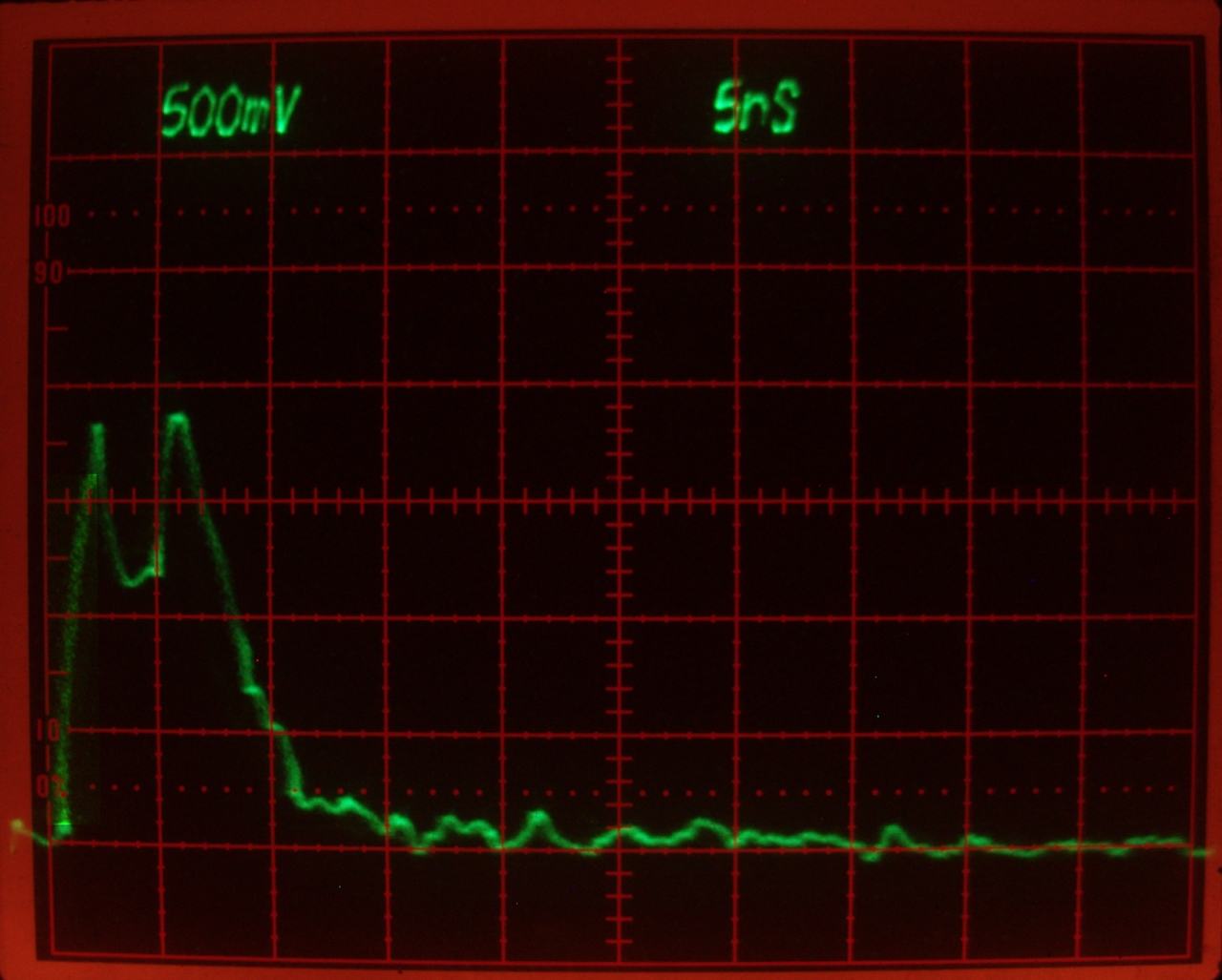
At lower pressures, however, the pulse becomes slightly
longer (the FWHM pulsewidth in this next photo is almost
7.5 nsec; for some of the pulses it was closer to 8
nsec), and I begin to see evidence of a second peak.
Here is ~40 Torr:
Remember, the vertical scale is not significant;
all it tells you is the output voltage from the detector,
which depends on many factors. In these two cases, I had
different amounts of attenuation in place.
I am a bit wary about the peak issue, partly because some
of it may have to do with which part of the beam I am
sampling with the detector. Here, for example, is another
trace, which I believe was taken with the photodiode
exposed to the upper edge of the beam. The pressure is
probably about 104 Torr:
(I had to enhance the brightness of the leading edge,
because it was nearly invisible.)
I am not fully sure whether there is much difference in
the output power or energy with the OC in place, but I
have some indication that there may be a slight
enhancement: I was able to lase a tilted cuvette of
Optic Whitener with part of the unfocused beam. (The
cuvette is too narrow to pick up the full width.)
(5 December, 2009, early AM)
I am now measuring about 1.3 millijoules per pulse at
roughly 70 Torr, which is about where I get the highest
output energy, though the peak is fairly broad.
Presuming the pulse to be 6.5 nsec FWHM, as it has been
during various measurements, this corresponds to at
least 200 kW peak, possibly somewhat more. I am not yet
satisfied; the sparking behavior and the fact that the
unfocused beam runs a dye cuvette both suggest that the
actual power and energy are somewhat higher than I am
measuring. Still, this evening’s measurement is
closer to what I would expect than my earlier attempts
at measuring this laser.
(06 December, 2009, evening)
In thinking about this set of issues, earlier this
afternoon, I decided that it might be a good idea to
look at the discharge with my fast photodiode, and
get a sense of its timing. As a preliminary exercise
I filled the head with about 33 Torr of helium, and
put a ceramic tile in front of the output window.
When I fired the laser, I saw a little bit of grayish
light on the tile, which seemed slightly odd, so I
put one of my regular paper targets in front of it.
When I fired the laser, I saw the typical fluorescence
on the paper.
That is, even with no nitrogen in the gas mix there is
enough air leaking into the head that it lases.
I strongly suspect that at least some of the leakage
is through the sidewalls, and I am now thinking about
building a third head for this laser. If I do so, I
will write a new page about it.
More as it becomes available...
(14 November, 2009, evening)
Yesterday evening, I was able to lase an acidic solution
of 4-Methyl-Umbelliferone. Aside from its trifluoromethyl
derivative, this dye has the broadest tuning range of any
laser dye, as far as I’m aware. (Basic solutions of
4-MU are very easy to lase, and have tuning range of
perhaps as much as 100 nm; acidic solutions have been
reported to have tuning range as wide as 170 nm.)
Here are two views; in the first, the [single] mirror is
misaligned. Notice the purplish cloudy area around the
reflected beam (to the right of the main beam); the
focus is on the cuvette, and the camera moved slightly
during the exposure. In the second photo the mirror is
aligned; I focused the camera on the target rather than
the cuvette, so the pattern is crisper.
Citations for some interesting papers about nitrogen and other lasers...
To the first page in this set, a general discussion
of the issues involved in designing and building a
high-performance nitrogen laser
To a page about my initial effort to produce a
high-performance nitrogen laser
To a page about my continuation of that effort,
which resulted in a laser that puts out about 100 kW and
can operate without a vacuum pump
To a “How-To” page about that laser
To an interim page about my effort to scale up a published design
in order to enhance its performance
To the first page about this laser
To the third page about this laser
To a brief “How-To” page
about building the design I discuss on these two pages
To a page about my current (late 2006) effort to build
a less-expensive laser with even better performance
To the Joss Research Institute Website
To my current research homepage
My email address is a@b.com, where a is my first name
(jon, only 3 letters, no “h”), and b is joss.
My phone number is +1 240 604 4495.
Last modified: Wed May 10 14:50:15 EDT 2017
First Light:

Power and Energy Measurements
Using the Laser
References
the Joss Research Institute
Contact Information: