(~22 October, 2010, ff)
This page describes the process of constructing a small hollow-cathode laser that has argon ions as its active medium, and uses helium as a buffer gas. My objective is to make the laser relatively easy to construct and operate, and to avoid parts that are expensive, difficult to obtain, or require much machining.
I also hope to use this platform to test a helium-iodine mixture, so I will be using stainless steel end fittings, as iodine reacts with brass. If you decide to build one of these and you do not intend to put iodine into it, you can use brass fittings.
The helium-argon laser operates at 476.5 nm, close to the usual blue argon wavelength (488.0). The gain is likely to be relatively low, perhaps 6% per meter, but He-Ar hollow-cathode lasers with active regions as short as 10 cm have been successfully operated, and the active length of this prototype will be 30.5 cm, so there is a decent chance that it will be feasible. I expect to use ordinary argon-laser mirrors, which should provide adequate feedback if I obtain single-pass gain of a few percent.
(NOTE, added 25 December, 2010: If you don’t want to read my entire [rather messy] track through this project, which was informative but not directly successful, please see either the next page, which deals with a different design, or the page after that, which continues the work of this page.
After reading a number of journal articles about various
hollow-cathode designs, I have decided to try a
quadrupole structure (see the note immediately below)
for the first version of this laser. If that fails, I
will probably retreat to some version of my earlier
design, which is shown on the previous page in this set.
Note: A dipole has 2 parts, and it has opposite charges or poles across from each other:
+ -
A quadrupole has 4 parts, and it has like charges (or poles) across from each other:
+  -
-  +
The quadrupole hollow-cathode discharge depends on a characteristic aspect of the Paschen curve: where the electrodes are very close together, a discharge will not form at certain pressure levels. I may be obliged to find the relevant pressure range by experiment, but with some luck that won’t be too difficult; I should be able to do it at a very low power level. Once I have the pressure in the correct range, the discharge should confine itself to the bore of the device.
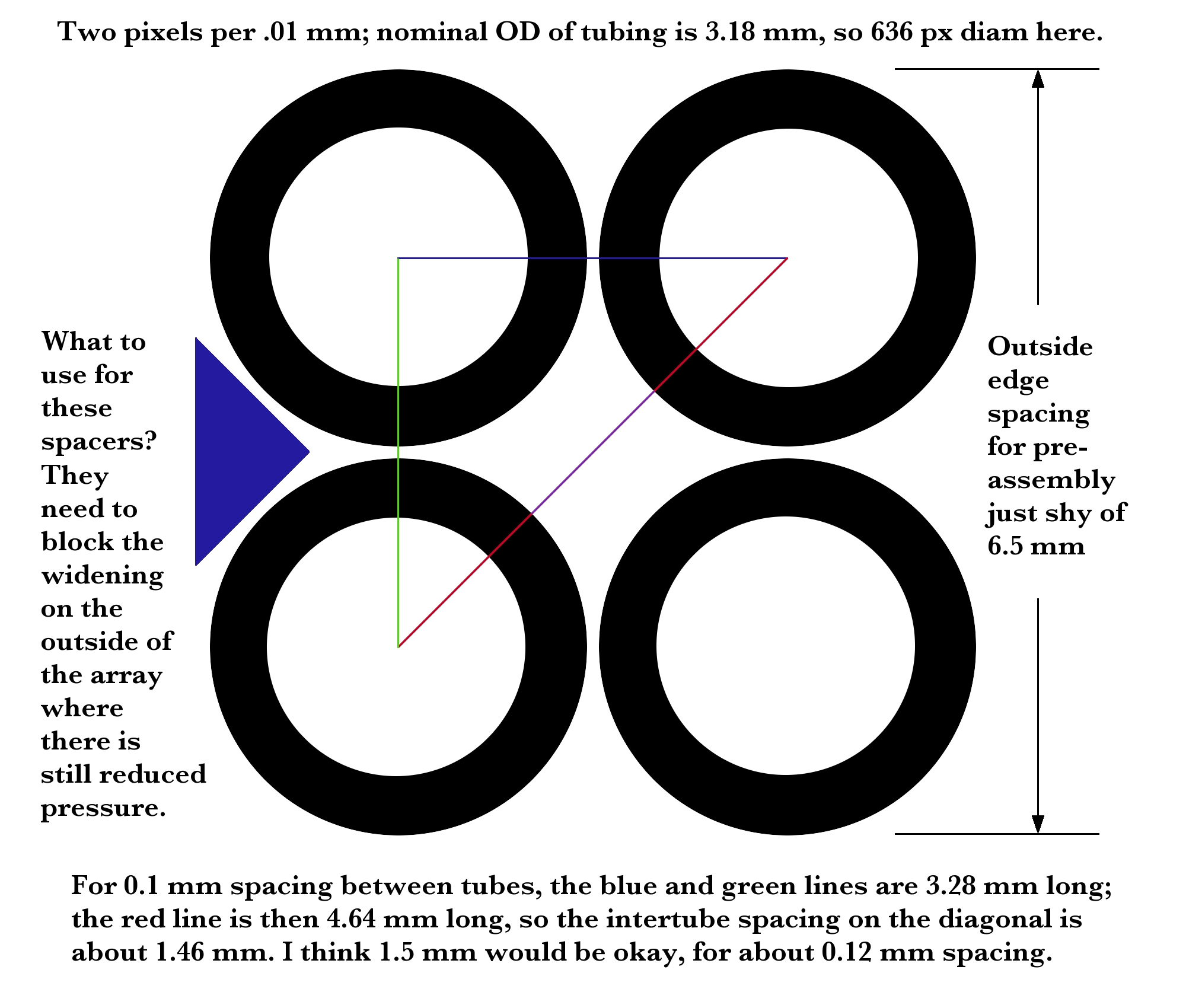
I bought four small (3.18 mm nominal OD) stainless steel tubes at a local hobby shop, to form the basis of the quadrupole. It is fairly easy to calculate the distance across the bore, given the diameter of the tubing and the spacing between tubes in a pair:
(One reason why I decided on 1.5 mm bore size was that I was able to get 1.5 mm square plastic rod at the hobby shop.)
It turned out that the tubing was larger than its listed nominal size, but not by very much. I positioned a pair of tubes between two aluminum rulers that I held in place with weights, and glued a thin plastic rail between them with epoxy. This is suboptimal, as the plastic will contaminate the gas if it gets hot, but I am hoping that it will do for this prototype. (I have ordered some slightly larger stainless steel tubes, and I am thinking about what to use in place of the plastic when I build the second version of this device.)
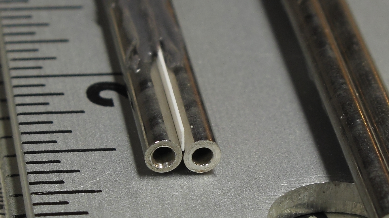
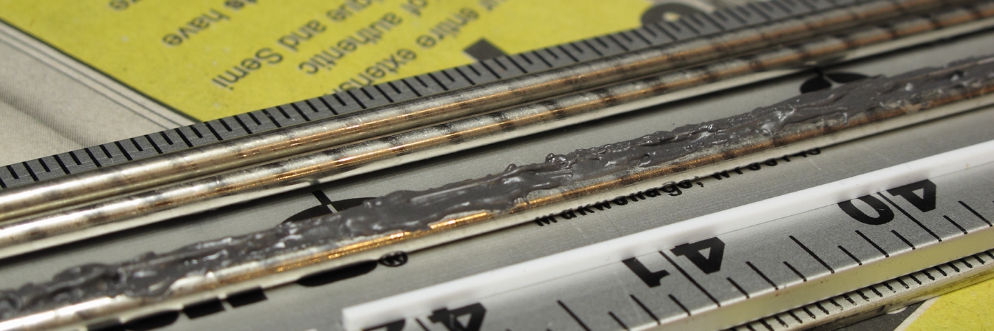
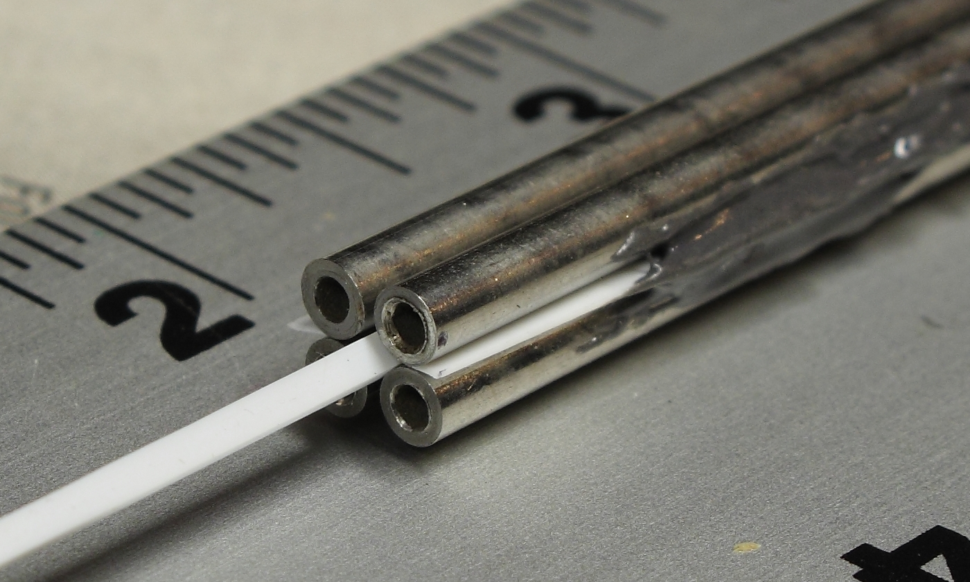
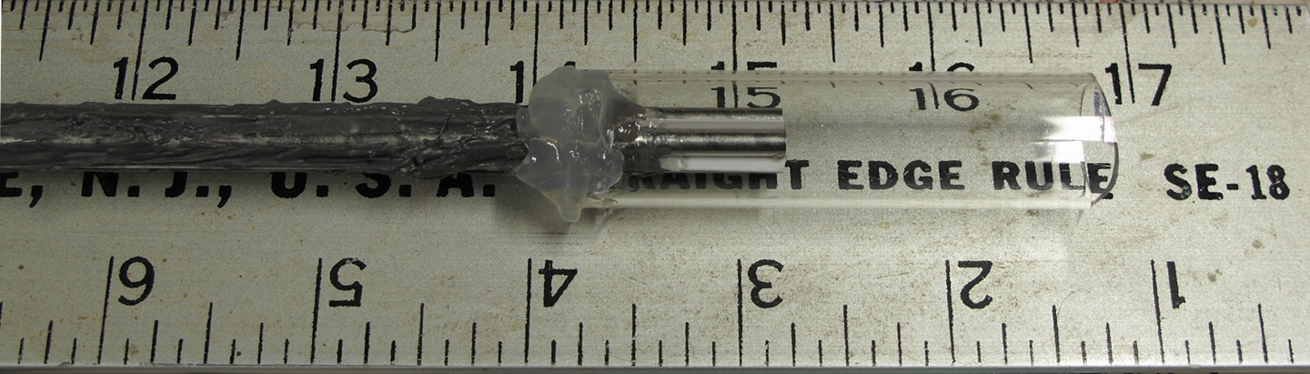
Here are some preliminary views of the first version, during assembly. First, a view of the ends of two of the stainless steel tubes, showing the position of one of the blocking insulators that should (I hope) prevent a discharge from forming outside the central region. Second, a side view of one pair of tubes, showing the J-B Weld epoxy that holds the tubes and the blocking insulator in place. Third, a mockup of the quadrupole assembly, with a spacer extending out from the end.
(24 October, 2010, afternoon)
It turns out to be surprisingly difficult to position the tube pairs to glue the third insulator into place. I am hoping that small dabs of silicone rubber caulk, applied to the ends, will help. If I can once get the gluing started, I should be able to complete it fairly easily.
(Late that evening)
I think I’ve managed to position the tubes almost adequately, and I have put the 3rd insulator in place with 2 dabs of epoxy. Tomorrow I will cautiously invert the assembly and see whether I can adjust the spacing so I can start attaching the 4th insulator.
(31 October, 2010)
I have completed the initial construction of the quadrupole structure, and I have put glass tubes on the ends with silicone rubber aquarium caulk:
Here’s a close-up of one of the ends:
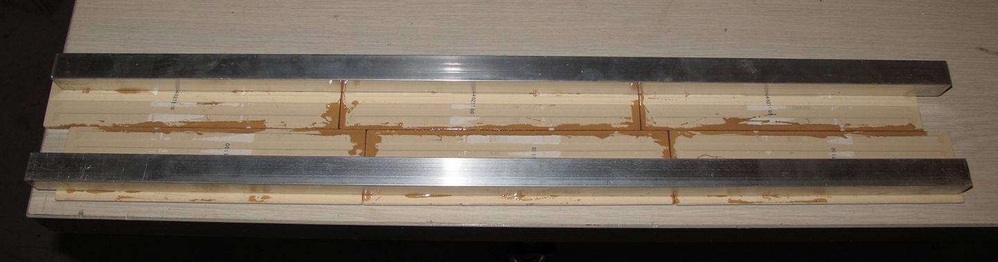
Meanwhile, it becomes necessary to have a base on which to put the laser head, so I am constructing one. For ease and simplicity, I decided to use two 24" lengths of square-cross-section aluminum tube from the hardware store (a single 48" piece, cut in half) as stiff members in a sandwich, and ceramic tiles as skins. Here is the bottom, after initial preassembly:
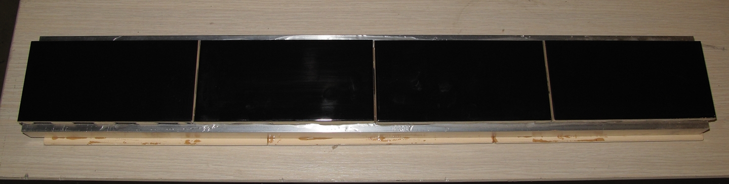
Here is the completed base:
Now I need to put endpieces on the tube, with gas and vacuum ports, and with mirrors. I am thinking about mirror mount structures. I am also thinking about the electrical connections to the tube; my initial notion is to use conductive epoxy to connect pieces of brass shim stock to the individual tubes of the quadrupole. (In a fancier world, I would have used special solder and appropriate flux to attach tabs of stainless steel shim stock, but I don’t happen to have any of that solder on hand. If I make a copper-vapor version of this laser, as I plan to do if I can get this initial version to work, I will use copper tubes, and I’ll attach brass shim tabs with ordinary tin-silver solder.)
(That evening)
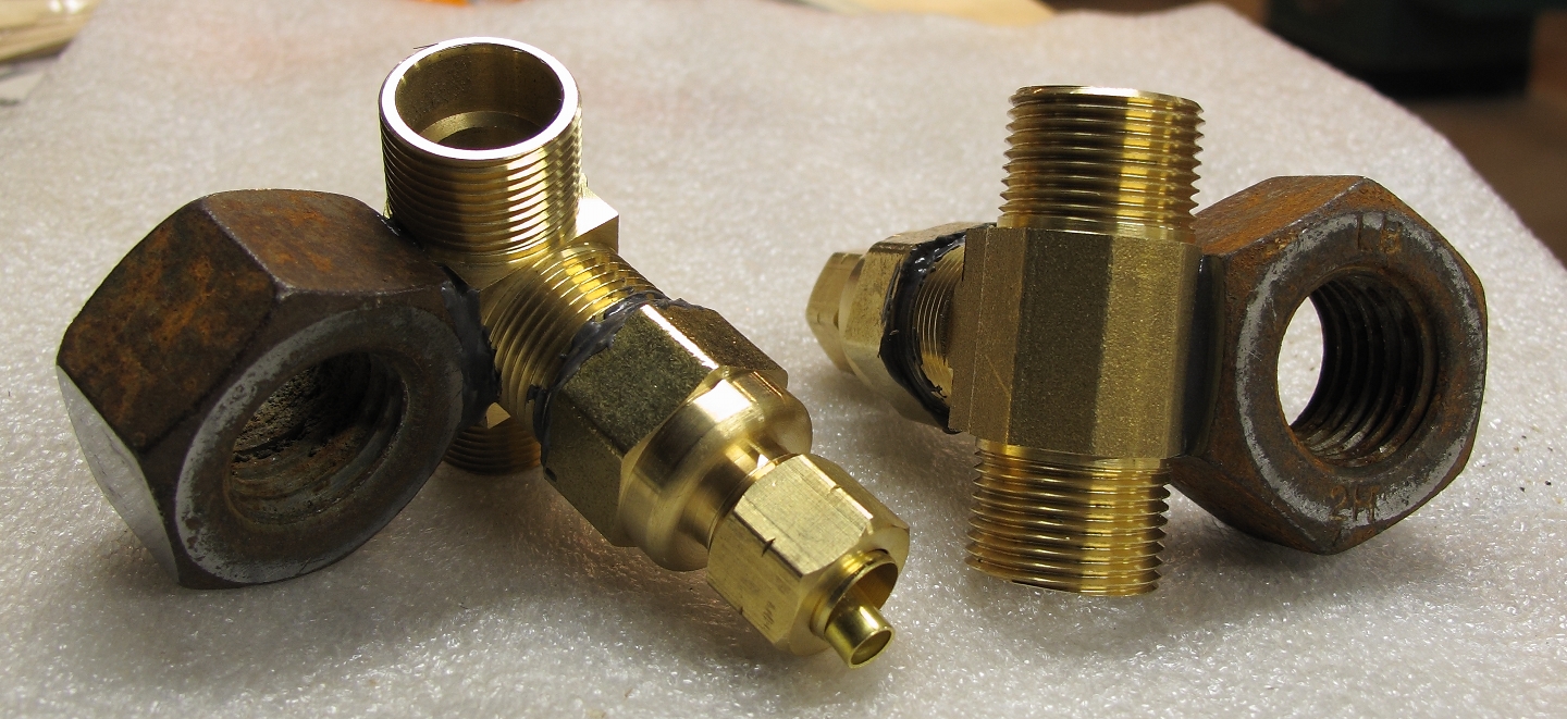
I have changed my mind; I’m building the tube with brass end-fittings, at least for this first incarnation, as they are readily available. I got a pair of compression Tee fittings today, 5/8" size, and a pair of FIP-to-3/8" compression adapters. (I can do gas and vacuum via 3/8" tubing, but that’s the largest size I have on hand.) The adapters do not actually fit onto the threads of the compression fittings, but they screw on about half a turn, which is enough because I’m holding them in place with J-B Weld epoxy (which is now curing). The glass tubing doesn’t quite go into the 5/8" opening, but I will be able to hold it in place with aquarium caulk, and that should be good enough for vacuum debug, initial testing, and (we hope) operation.
(04 November, 2010)
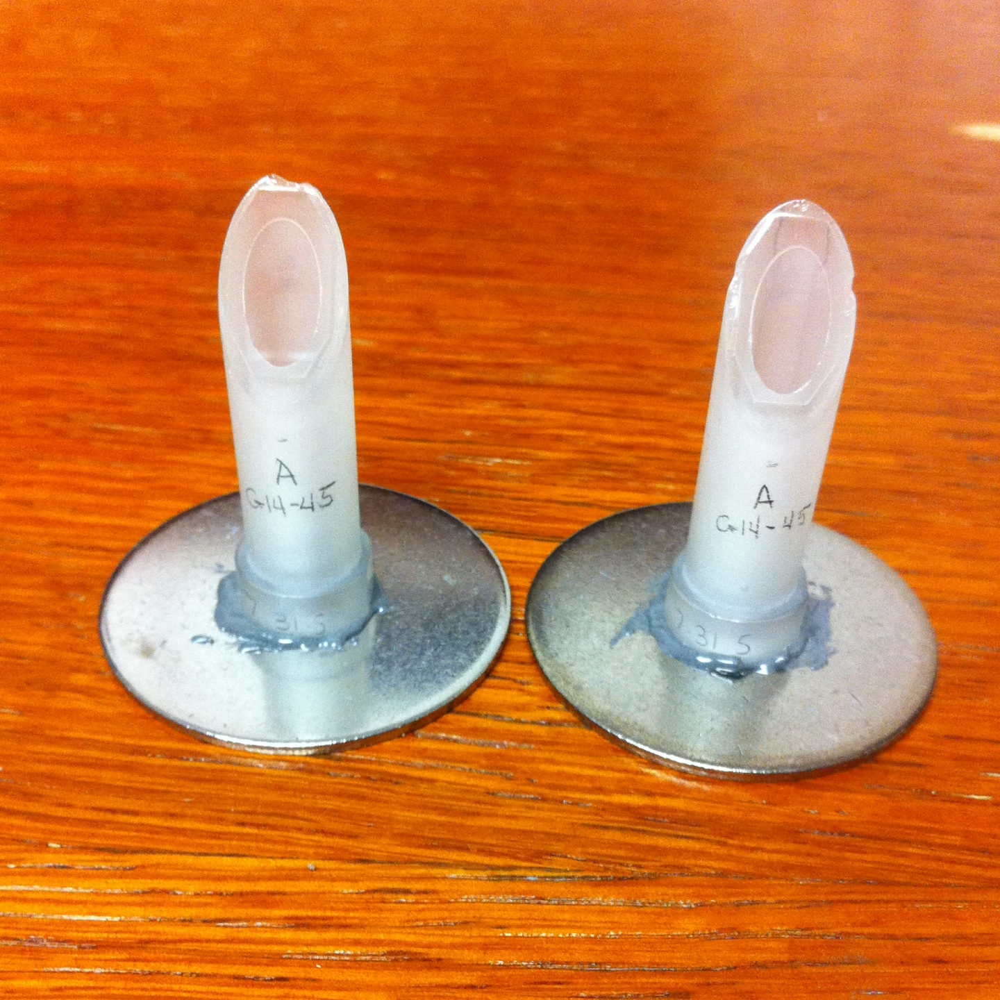
Here are the end fittings, with stands epoxied to them.
It should be relatively easy to assemble the head, after
which I will be able to start looking for vacuum leaks.
I am currently in California for a conference, though,
and will continue with this project when I return, in
a week or so.
(14 November, 2010)
That was one amazing trip, but this isn’t the place to discuss it. Back to HC discharges...
Yesterday I attached one of the end fittings to the base. Today I hope to attach the other one, and I will probably attempt to set the quadrupole assembly between them at the same time. I’m worried about the stresses involved in attaching the gas and vacuum hoses, and I may try clamping the fittings down while I’m tightening the hoses in place.
(17 November, 2010, early AM)
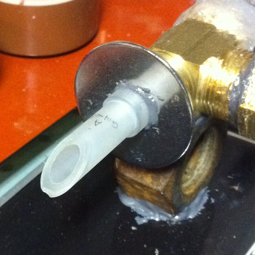
I built the rest of the head...
...using a thick microscope slide, which I cut into two pieces, for end windows. Here’s a detail of one of the ends:
At least for now, I just want to be able to view the discharge, once I find and fix the vacuum leaks. Attempts at lasing can wait until I have a decent sense of the requisite parameters for a clean and reasonably stable discharge. If I get that far, I will replace the windows with mirror mounts containing argon laser mirrors.
This evening I connected the head to the gas supply and vacuum hoses, and tried pumping it down. It fairly promptly went to less than 100 Torr, which is something of a start. As soon as I have time and energy I will find and plug as many leaks as possible, and then it will be time to attach a power supply. I expect to use the transformer from an older microwave oven, probably with a rectifier, and eventually with a small capacitor (and possibly an inductor) so I can push several amps through the discharge in pulses of perhaps a few microseconds’ duration. I hope that will be enough to threshold of the He-Ar+ line at 476.5 nm.
First things first, however. If I can’t pull vacuum on the head there isn’t much point trying to run a discharge, and if I can’t get a clean discharge there isn’t much point trying to lase the thing.
(19 November 2010, morning)
By the simple (but regrettably crude) expedient of slathering aquarium caulk over the quadrupole section and the ends of the glass tubes, I got the system to pump down to less than 20 Torr yesterday. In vacuum terms that’s nearly open to the atmosphere, but it is a lot better than what I saw when I first connected the head. I have some suspicions about the hose connections, which look to me like they are intended more for copper tubing than polypropylene, but I can cover those with caulk as well, at least on a temporary basis, to find out whether they are actually at fault. If they are, I can eventually change over to Delrin compression rings in place of the metal rings that came with the fittings.
(26 November, 2010)
I managed to get the limiting pressure down to just under 5 Torr. Then I dug out the ultrasonic “sniffer” that we acquired on eBay some months ago, listened to the tube with it, and promptly found some leaks near one end of the quadrupole structure, which I caulked over. The tube now pumps down to about 2 Torr. I tried the sniffer again, but didn’t hear anything I could clearly identify; I may give it another shot with the gain turned up a bit further.
Meanwhile, however, it has occurred to me that the design of the first quadrupole leaves something to be desired: the spacer/insulators probably provide a relatively short path, over which the HV can probably arc at least as easily as it can go through what should be the active region. Fortunately, I have already acquired some parts with which to build a second quadrupole that stands a fair chance of working better. Here’s a diagram:
(For some arcane reason I am having a bit of trouble with the GIMP; the size of the pink square should be listed as ~2.82 mm. If the tubes are only ~0.3 mm apart, as in fact they turned out to be, this square is just under 2.4 mm across.)
Equally fortunately, the new stainless steel tubes are the same length as the first set, so I will be able to put the new center section in place without modifying the end fittings or the baseplate. I have started to build it, and the first square insulator/spacer sat right down in the correct position and with decent orientation, about as I expected it to do given the shapes of the insulator (ABS plastic from the local hobby shop) and the tubes.
(27 November, 2010, late evening)
The square-cross-section insulators are much easier to position than the thin slats I used on the first prototype of the quadrupole section (see above), and the fact that everything is larger also makes construction less difficult. Here is a view of the first pair of tubes, with the center insulator placed and partly secured:
(Pardon the crappy color balance; iPhone macrophoto taken with available light, which was mostly old-style fluorescent tubes.)
The fact that the insulator is slightly off-angle should not be a problem. I am fairly certain that the important things are: first, that the spacing between the tubes is not too far off spec, and is reasonably uniform; and second, that the insulator provides a fairly long arcover path, thus maximizing the chance that the discharge will occur where I want it to. As in the previous build I set the spacing with a pair of straightedges, so it should be (and appears to be) reasonable. Meanwhile, you can see some small areas of epoxy (the gray material) in the photo; I added more after the photo was taken. These should stabilize the structure mechanically, and more RTV caulk will seal it for vacuum.
The second tube pair is also partly secured now, and I will add more epoxy to it tomorrow. I also need to add the end parts to the insulator/spacers; I will probably do the ends of the pairs first, then put the pairs together to make the quadrupole, and finally add the remaining 4 end parts. (For some reason, I suspect that it will be easier that way than trying to add all of the end parts at once after the quadrupole is built.)
(30 November, 2010, afternoon)
...Accomplished. Now I have both halves of the quadrupole built, and I need to figure out how to put them together. The big issue is the spacing; it turns out that the tubes are probably about 0.3 mm apart in each pair, so I would like to have the pairs about 0.3 mm apart in the final assembly. I acquired some ABS plastic strips, but they are only 6.25 mm (or so) wide, and I need them to be closer to 8 or 9 mm wide. [[Note, added later: I thought they were 0.3 mm thick, but when I went to use them I found that they were 0.5 mm thick. Fortunately, I had also purchased some 0.3 mm strips, though those were only 2.5 mm across. I ended up using them anyway; see next entry.]] I may be able to clip the edge off one, and butt it up next to another, but doing that with the required accuracy would not be trivial. I don’t think I can just overlap them & glue them together, as the result would have a wide area with too much thickness, which would get in the way.
Thinking about it.
(04 December, 2010, early AM)
It occurred to me that if I didn’t push the middle parts of the sections together too hard, I could set the spacing by putting 0.3mm-thick shims between the halves, out near the ends of the sections (so they wouldn’t interfere with the ABS insulator/spacer). It was a bit tricky to get it all in place and fairly stable, but I eventually managed. I have RTV caulk on the insulator now, and will soon dot some J-B Weld on it to hold things more firmly in place. Once that has cured I can flip the assembly over, set the shims in place again, and do the other edge. Photos:
As you can see, one of the pairs (the one on the right in the second photo) appears to be spaced slightly wider than the other. My hope is that this will not be a huge problem.
Meanwhile, I have verified that the new quadrupole will [just barely] fit inside the existing glass tubes, so I won’t have to do any other rebuilding. This is a big relief.
(04 December, 2010, early evening)
The fourth spacer/insulator is now in place, and I will be adding epoxy when the RTV caulk has had a chance to cure. Then I will have to add the four remaining ABS endpieces, make sure that all of the spacers are securely in place, and caulk all of the joints. Once all of the glue and caulk have cured, it will be time to put the new center section in place and start doing vacuum debug.
...Which reminds me that I need to finish a power supply for this tube. I have a microwave-oven transformer, with a rectifier on its output; need to add some ballasting (probably resistive) and perhaps later a modest PFN so it will drive the tube with little pulses.
(05 December, 2010, evening)
The four short ABS pieces are now in place, and I have put caulk in one end of each tube so I won’t waste gas that could be flowing through the active region. I want to get some more dabs of epoxy on the quadrupole for stability, and I want to attach some brass shim for electrical connections, but after that I can reassemble the head and start finding vacuum leaks.
(06 December, 2010, evening)
I think I’ve put enough epoxy on the quadrupole. The next order of business is to make electrical connections to it, and to do so without interfering with my ability to find and plug vacuum leaks. (This afternoon I priced some conductive epoxy. It was more than $42, which is well over twice what I paid for it the last time I bought it. I will be using my old stock [if I can find it and get it out of the tubes], and hoping that it hardens.)
Meanwhile, I am seriously considering putting Brewster-angle windows on the ends of the tube. This avoids exposing the mirror coatings to the vacuum and the discharge, and it also makes it easier to “tweak” the mirror alignment. As a side-benefit, it provides polarized output.
(07 December, 2010, evening, and 08 December, morning)
The quadrupole section now has enough dabs of epoxy on it, and I have applied caulk to one of the 4 faces. Still looking for my [ancient] conductive epoxy...
(09 December, 2010, afternoon)
All four faces are now caulked. I will presumably have to add bits of caulk here and there to plug leaks, once this new quadrupole section is in place.
(26 December, 2010, evening)
I am now in the middle of de-leaking the new head. With some luck, it won’t be too difficult. I also have the beginning of a temporary power supply, but I won’t need that until the head holds a reasonable vacuum. At this point I can still hear some of the larger leaks, and I have not needed the ultrasonic sniffer yet. With some luck, however, I will reach that point later this evening.
(28 December, 2010, early AM)
The sniffer has done its work, and the tube now pumps down to 3.2 Torr. That isn’t good enough, but it is far better than what I was able to achieve even a few hours ago. I will be working on the power supply as I try to get the tube down to appreciably less than 1 Torr.
(29 December, 2010, early AM)
I tweaked the vacuum manifold a bit, and got the head to pump down to about 1.3 Torr. That was good enough for a first test, so I rigged up a power supply (the transformer from an old microwave oven, with 2X 1.8 kOhm 25W resistors in series with the output) and made some [nonlaser] light. Here is the view through one of the end windows. Tube unlit; tube lit, voltage about right; voltage a little bit too high...
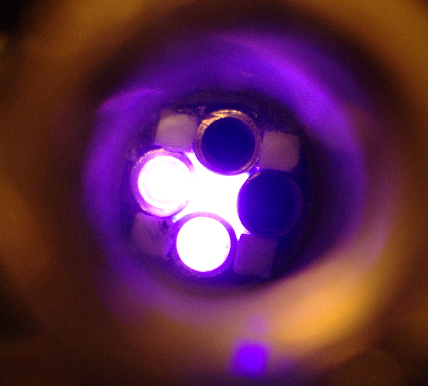
The fact that the end turns into a lightbulb (in the third photo you can see the glow obscuring part of the end of one of the stainless steel tubes) if I apply a voltage that is even modestly too high is annoying, but probably not a show-stopper. It will steal some energy and thus decrease the efficiency of the laser (if, in fact, I can convince this machine to become a laser), but I can’t see it actually interfering. However, before this device will become a laser I have to be able to get a fairly clean fill with helium and argon, which means that I have to improve the vacuum significantly; and I definitely want to put Brewster windows on the tube and get mirrors into place. As I mention somewhere above, I also strongly suspect that I will end up building a little PFN so the tube runs on brief pulses. One thing at a time...
(That afternoon...)
Here are the Brewsters, being attached to their carriers:
(31 December, 2010, early AM)
Both Brewster windows are now attached to the tube, and I am letting the RTV cure. Tomorrow (later today, actually) I will try pumping the tube down. If I can get close to a decent vacuum, maybe I will try aligning some mirrors, and we can see what happens with some helium and argon. Meanwhile, here is one of the windows in place:
I doubt that they are aligned well enough to be better than high quality AR-coated windows, but this is the first time I’ve ever built a laser with Brewster-Angle windows, so I will be pleased if they work.
(1 January, 2011, early evening)
Presumably because of outgassing from the RTV, I cannot pump this head down far enough to obtain lasing from a mixture of helium and argon. It is not suitable for the He-N2+ laser, which wants an atmosphere or more of helium and very fast pulsing. It may, however, be close to suitable for the He-I2 laser, which operates at several Torr, and I will be testing that when I have time. I may have to swap out the OC, however, which is optimized for argon; He-I2 has only a few lines in the blue and blue-green, none of which seems to be as strong as the line at 612.7 nm in the orange.
(somewhat later, but still that same evening)
I substituted a HeNe MaxRef rear mirror for the OC, but failed to get any output with I2 in He at room temperature. I think it’s time to go back to the drawing board; the next version of this laser will not use RTV as a sealant. In addition, because of the difficulty I had with discharge past the ends of the bore, the next version will have a structure in place to help prevent that.
(Note, added early January, 2011: I improved the
vacuum system, and decided to try this head again, with
longer electrical pulses. Unfortunately, I was unable to
get a clean discharge. I have learned some important things
from this head, however, and I will continue working on
the design in the future.
Please see the next page in this set for further progress with a different design, or the page after that for further progress with this (quadrupole) design.
Back to the first page in this set
To the Joss Research Institute Website
To my current research homepage
My email address is a@b.com, where a is my first name (just jon, only 3 letters, no “h”), and b is joss.
My phone number is +1 240 604 4495.
Last modified: Wed May 10 15:10:38 EDT 2017