I: The Copper Quadrupole
(2011.0226)
For the first version of this laser I built a quadrupole from copper tubing. For various reasons it was not successful, but I did learn quite a bit from it. This time I am using glass (rather than plastic) for the insulators on the sides of the structure, and (as mentioned above) epoxy rather than RTV. It also became clear while I was working with the earlier machine that there were some issues with the structure as it was designed and built; for example, the discharge confined itself to the bore only under fairly restricted circumstances. It should (we hope) be relatively easy to prevent arcs at the ends of the quadrupole, by putting a conductor in close proximity; this is the same method I am using to avoid arcs between the tubes that serve as poles in the structure, and relates to the Paschen curve (as mentioned on page 016a).
Here is a preliminary photo of one pair of electrodes at an early construction stage:
The small glass tubes that I’m using as insulators are not easy to see in this photo; they are melting-point capillaries that I acquired on eBay. (Hematocrit capillaries would also work.) If you look carefully, though, you can see the ABS spacer between the two copper tubes. It holds them 0.3 mm apart for initial assembly.
I have set up both pairs of tubes with dots of J-B Weld to hold the glass tubes in place, but I have not applied any more epoxy to them yet. I will probably do that before I attempt to assemble them into a quadrupole structure, as it seems much easier that way.
Meanwhile, I am also rebuilding the vacuum manifold on the roughing system that I’m using with these lasers; but that is peripheral to this effort, and is discussed on a different page.
(2011.0227)
I have applied transparent epoxy to one side of each pair. Here is a detail of one end:
(The epoxy is on the right half of each pair. It is not easy to see.)
(2011.0228, afternoon)
Both pairs now have epoxy down both sides of the capillary tubes. I hope to assemble them into a quadrupole structure this evening. I’m a bit concerned about drilling holes into the sides of the tubes, and I think perhaps that will wait until the quadrupole is built and strengthened. (I want to block off the ends of all four tubes, and have vacuum only down the bore of the laser.)
Once I have the quadrupole built, I expect to use TO-220 ceramic insulators as endpieces. I have not yet decided whether to attach end fittings directly to the endpieces or interpose short pieces of glass tubing, but at the moment I am leaning toward direct attach.
(Later, that evening)
I spaced the halves of the quadrupole 0.3 mm apart with a wider (~6 mm) strip of ABS plastic, and I have put the third set of glass tubes on with small dabs of J-B Weld. When the J-B has had time to cure, I will probably add epoxy as I did with the halves of the quadrupole, to strengthen the structure before I turn it upside down and apply the final set of tubes.
(2011.0308, early AM)
Some epoxy got between two of the tubes, and I have ordered a set of very thin circular sawblades, in hopes that I can remove some of it. That should let me operate this quadrupole. In the worst case I can still separate the two pairs of tubes, after which either I should be able to remove most of the epoxy that is in the wrong location and put the two pairs back together again, or just build another pair and reconstruct the quadrupole using it.
In the meanwhile, I have acquired a pair of end fittings, and I continue to think about relevant issues. One problem with this design, just as with the string-of-beads design in the first section on this page, is differential thermal expansion. I cannot permit either head to get too hot during operation.
(2011.0326, afternoon)
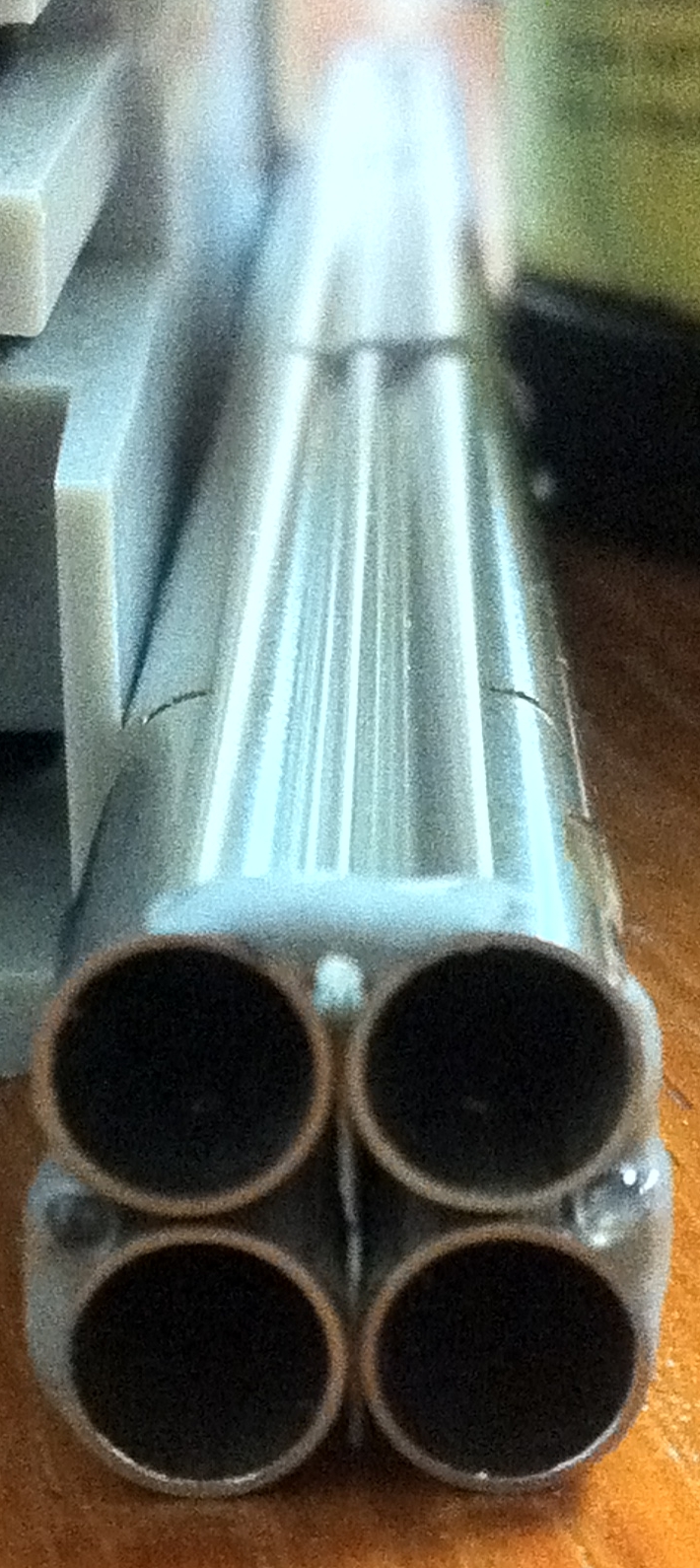
Here is a preliminary look at the ends of this quadrupole and the stainless steel one, with a rule so you can get a good sense of the overall sizes and the bore sizes:
I still have to fill the ends of all the tubes, and then cut small holes in the copper ones. (The stainless steel tubes already have laser-cut holes in them.)
(2011.0304, afternoon)
I have been interrupted by a conference, but I did manage to fill the ends of the tubes with epoxy. I still need to drill a hole in each of the copper tubes.
(2011.0615)
Some time has passed. I have made endpieces for both tubes, and epoxied them in position. Here is one of them, being glued to the copper quadrupole:
I was fortunate here; toothpicks were about the right size to serve as positioners. Both endplates are now attached, and I have acquired brass compression tees to serve as gas inlet and outlet and to hold mirror mounts.
[[More as it transpires...]]
My rationale here is that He-I2 operates at
relatively high pressures (several Torr), emits several
visible lines, and lases well in hollow-cathode
structures that are a few mm across. It may even be
possible to use mirrors from a HeNe laser, as the best
line in the visible spectrum seems to be at 612.7
nm. That’s a bit more orange than the common 632.8
nm HeNe line, but still fairly close, and I hope that
the mirrors will have good reflectivity (though it is
possible that I will get beams from both ends of the
device, assuming it lases at all).
If I can build a structure that is decently leakproof,
I should be able to lase a helium-argon mixture in it;
this version of the argon laser emits at 476.5 nm, a
pleasant blue color. This, however, involves only a few
milliTorr of argon, and adjustment is likely to be
rather tweaky.
.-=^=-.-=^=-.-=^=-.-=^=-.-=^=-.-=^=-.-=^=-.-=^=-.-=^=-.-=^=-.-=^=-.
(Earlier note: 09 January, 2011, morning)
Jarrod Kinsey has pointed out one of Dr. Mark Csele’s
pages, on which he describes running a small CW argon
laser in pulsed mode. For some reason, he finds that he
must apply remarkably long electrical pulses (more than
10 μsec) in order to get any lasing. I was using
much shorter pulses with an earlier version of this
laser, and did not succeed; this may help explain why.
.-=^=-.-=^=-.-=^=-.-=^=-.-=^=-.-=^=-.-=^=-.-=^=-.-=^=-.-=^=-.-=^=-.
I will be introducing the iodine (or argon) along with
the helium, so I don’t want the wall material to
sputter into the discharge or to react with iodine.
Stainless steel seems to be a reasonable material in
both regards, and it is readily available, so I have
used it here. (See the photo at the end of the previous
section.) I bought the tubes from
The Electronic Goldmine;
I think they cost all of 99 cents each, plus shipping.
I got 6 of them, knowing that I would probably have
trouble with at least one of the pairs (which, in fact,
I did — I didn’t align the tubes well enough
when I glued the insulators to them).
The Paschen relationship for helium suggests that the
highest viable pressure for a structure that amounts to
a tube with inside diameter of ~2.5 mm is a few Torr.
That is somewhat low for helium-iodine, which has been
found in at least one study to operate best at about 13
or 13.5 Torr; but this design may be viable anyway
— at least one published study has used a
comparable design at pressures of more than 10 Torr.
(2011.0326, afternoon)
See the end of the previous section for a view of the
end of the stainless steel quadrupole. This quad has a
problem: in one area there is epoxy between the tubes.
It does not obstruct any of the bore, and if I am very
lucky it will not have any effect. If I am not so
lucky, a discharge will form across the epoxy surface
instead of inside the bore; but we’ll cross that
bridge if and when it burns under us. (If such a discharge
did form, it would probably carbonize the epoxy and
short-circuit the tube. It’s a good thing that
these tubes are inexpensive.)
(2011.0404, afternoon)
I have filled the ends of the tubes with epoxy. The
next step is to put end plates on the structure. Then
I need to add gas ports and either mirror mounts or
Brewster-angle windows, or possibly plain AR-coated
windows.
(2011.0615, late afternoon)
This quadrupole went together reasonably well, and is
now almost complete. Here it is during construction; I
had just put the two halves of this quad together, and
you can probably see the styrene spacer in the middle.
The outer insulators, which are sets of melting-point
capillary tubes, are in place, but I have not yet
applied the epoxy around them that prevents vacuum
leaks.
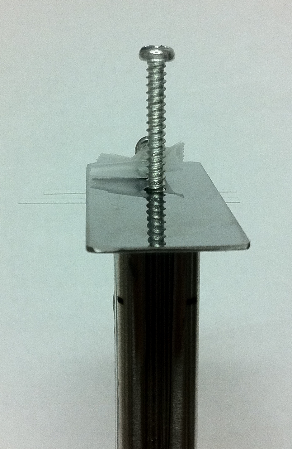
Here it is at a later stage, with one of the endplates
being attached to it:
Note the pieces of styrene ribbon being used as spacers.
It is easy for these to get stuck in the epoxy, but once
the end positions are established it is possible to take
the plate off, remove the styrene, and epoxy the plate
back on without the spacers — the existing epoxy
serves to maintain the spacing. (Yes, I know this
because I had to do it. The epoxy wicks into the gaps
very nicely when it is freshly mixed...) Notice also the
small machine screw; the hole is not in the middle of
the plate, and it kept tipping until I weighted it.
I have both ends attached now, and I need to find a pair
of stainless steel fittings to serve as the gas inlet
and outlet (and to hold mirror mounts).
[More as it transpires...]
My initial feeling about the active structure of this
laser is that I want to build something that has a
more-or-less-circular bore. Obviously, the structures I
built above, from round tubes, fail to meet this
criterion. There are two obvious ways to achieve a
circular bore, the first of which is to use a
“string of beads” structure like the one on
the next page, made of copper and brass for a copper
vapor laser, or of stainless steel for a He-I2
or He-Ar laser. The other is tweakier and more
difficult, but should have significantly better
performance. It is achieved by clamping 4 rods together
and drilling a 2.5-mm, 3-mm, or even 3.125-mm hole down
the line where they join. I would have to do this in
sections that are quite short, because I don’t
have any special drills, but that isn’t too
terrible. I debate whether to space the rods before or
after I drill them, and I think I would most likely
clamp them with the spacers in place. This effectively
provides a centerpunch at the point where they come
together, and gives me a bore that really is more or
less a circle. (If I were to drill first and then space,
the bore would be slightly off-round.)
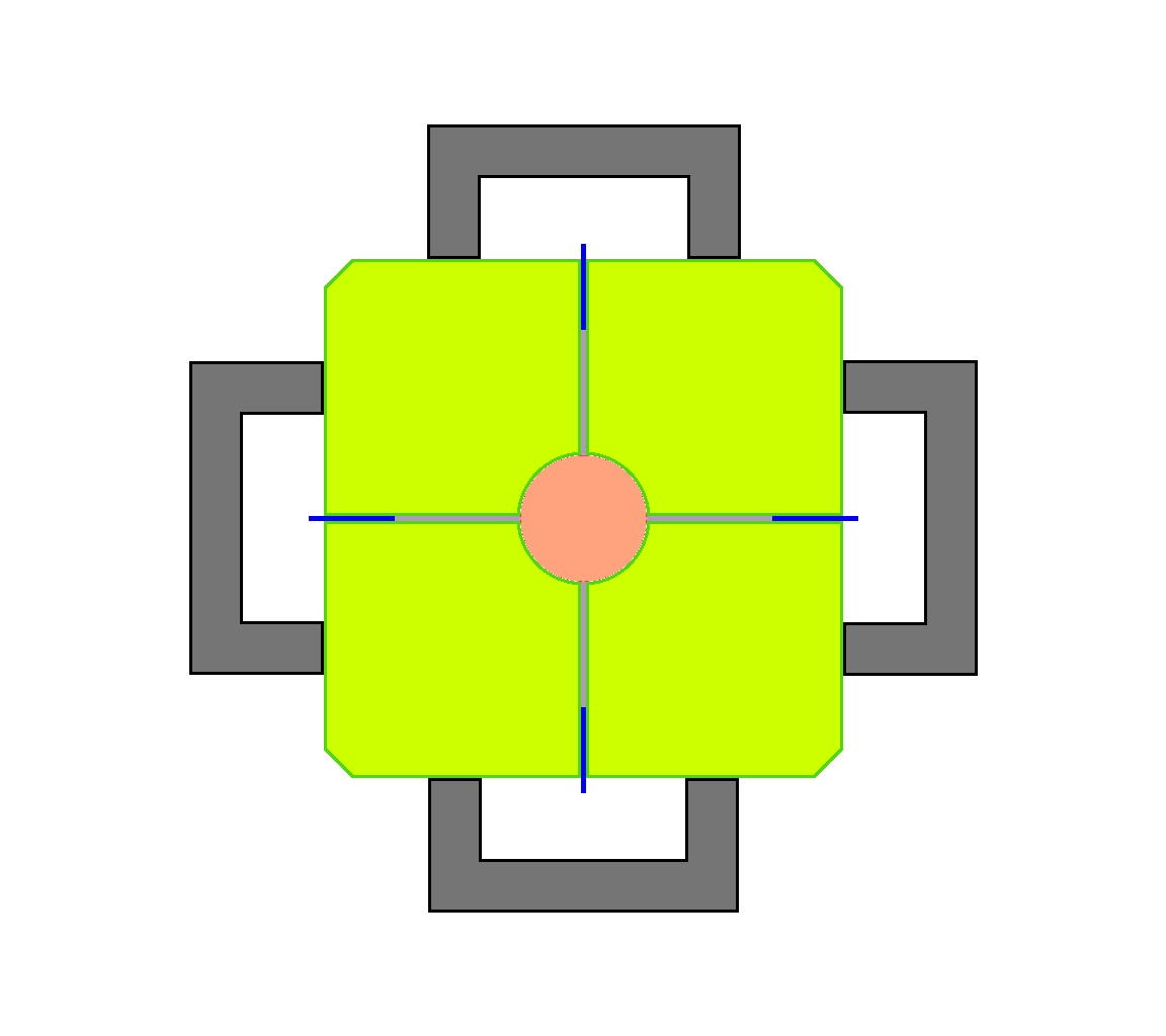
Here is a rough diagram, not to scale. The yellow-green
areas with green borders are stainless steel; the pale
pinkish-orange circle is the bore; the blue lines are
spacer/insulators. (I don’t have anything fancy,
so unless I can find some nice glass or ceramic ribbon
or maybe circuitboard that is about 0.3 mm thick, I will
probably use ABS plastic from the hobby shop, and try to
keep it well away from the discharge.) In addition to
providing insulation, these are somewhat structural; but
I strongly suspect that other external structural
members will be required, as the spacings between the
pieces must be maintained firmly. I have shown these in
gray with black borders; they should be regarded as
schematic rather than directly representative, as I
don’t know what they would (or will) look like
if I actually build a design of this type. Note that
the only areas that are under vacuum (other than the
bore, which is the salmon-colored circle in the middle)
are the thin (0.3 mm) gaps that extend out from the bore
to the spacers. They are indicated in mauve.
(02 January, 2011, early afternoon)
Frankly, this would be seriously nontrivial to
construct, and I have diverged in order to build
string-of-beads copper ion laser (see the next page) and
the quadrupoles described earlier on this page. Despite
being difficult, though, this design is attractive
specifically because the bore is circular. That
apparently enhances electron oscillation in the
discharge (which gives the laser its desirable
characteristics), and I suspect that it also has a
greater tendency to produce a
TEM00 mode
structure.
[[More as it transpires.]]
(02 January, 2011, afternoon, ff)
Here are some useful abstracts. In some cases I have
found and read the article at the University library or
online; in others I am probably going by what I have
found in the abstract, as that was enough information to
get me started.
Longitudinal hollow cathode copper ion laser:
optimization of excitation and geometry (Proceedings
Paper)
Abstract
It is demonstrated experimentally that for copper ion
lines laser excitation in a longitudinal hollow cathode
discharge (HCD) an optimum current density (approximately
1 A/cm2) exists. Above this value a saturation and even
decrease of the laser power is observed. Due to the
axial inhomogeneity of the longitudinal discharge the
possibility to increase the laser power by increasing
the cathode length is also limited. To determine the
proper cathode length for a sputtering copper ion laser,
the axial current and spectral lines intensity
distribution at conditions typical for laser oscillation
are measured, showing a maximum at the anode ends of the
cathode. Numerical modeling for exactly the same
discharge conditions and tube design is also
performed. The results are compared with the measured
data and reasonable agreement is reached. Based on the
results of the experiments and calculations we have
demonstrated that the most efficient laser oscillation
is achieved when the laser active volume comprises a
series of anodes and cathodes, each cathode with a
length of approximately 1 x 2 cm.
[Note: the “x” between 1 and 2 in that last
sentence is actually a “divided by” sign.
When I find the correct HTML code, I will restore it.
Unfortunately, I am not entirely sure what they meant
by it.]
The conclusions here put a severe limit on the performance
I can expect to get from my “string of beads”
sectional tube, with alternating anodes and cathodes; but
at least it appears that such a tube can be a viable laser.
Comparison of Cu-II 781 nm Lasers Using High-Voltage
Hollow-Cathode and Hollow-Anode-Cathode Discharges
Abstract
Voltage-current characteristics and the Cu-II 780.8 nm
laser performances are described for a novel segmented
hollow cathode and for three- and four-slot
hollow-anode-cathode (HAC) tubes. Each of these operate[s]
at a higher voltage and with higher slope resistance than
a conventional hollow cathode, and [they] produce improved
laser performance. The best laser performance is obtained
with the segmented tube. The application of a longitudinal
magnetic field raises the discharge voltage and enhances
the laser performance for the segmented tube, and raises
the voltage for the four-slot HAC tube. The magnetic field
lowers the voltage and reduces the laser performance with
the three-slot HAC tube. The voltage effects are attributed
to the deflection of the fast electrons by the magnetic
field strength, and represent experimental evidence for
the oscillation of electrons in a hollow-cathode discharge.
Note: I have performed minor editing on this, adding a
few commas and the items enclosed in square brackets.
This is a crucially important paper, and is probably
available on the Web in PDF format.
Dependence of the infrared output power of a hollow
cathode Cu+ laser on He and Ar pressures
Abstract
The dependence of the infrared laser power produced by a
hollow cathode copper ion laser on the He and Ar
pressure is reported. An argon partial pressure of 1
mbar is found to be optimum and nearly independent of
the helium partial pressure and discharge current. The
optimum He pressure is about 25 mbar, dependent on the
discharge current. A simple rate equation model is given
and compared to the experimental results.
Parametric study of a high-voltage hollow-cathode infrared
copper-ion laser
Abstract
A new, segmented-electrode, high-voltage, hollow-cathode, Cu II
laser, operating on the 780.8 and 782.5 nm transitions, is
studied. Parametric measurements are presented for the discharge
voltage, the spatially averaged copper-atom concentration and,
for the two transitions, the small-signal gain coefficient, the
laser threshold current and the laser output power. The
dependence of the laser output power on the active length, the
buffer-gas pressure and the transmission of the output coupler is
modelled using equations for a low-loss, homogeneously broadened,
standing-wave laser. For the 780.8 nm line, the lowest threshold
current is 0.19 A for a 5 cm active length and a 0.1%
transmission output coupler, and the maximum output power is 58
mW for a 3 A discharge current, a 7.5 cm active length and a 2%
transmission output coupler. This performance exceeds that of
conventional hollow-cathode lasers on the same transition, the
improvement being attributed to the increased operating voltage,
which gives a more efficient pumping discharge by simultaneously
raising the ground-state copper-atom concentration (through the
increased sputtering yield of ions bombarding the cathode) and
increasing the efficiency of ionization.
Dependence of Gain and Laser Power for Cu-II 780.8-nm Transition
on the Diameter of a Segmented Hollow Cathode Discharge
Abstract
The dependence of laser performance and discharge characteristics
on the diameter of a segmented hollow cathode discharge for the
Cu II 780.8 nm transition is presented. This transition has a
special importance since its upper level is common to potential
CW VUV laser transitions (150-170 nm). Laser tubes with internal
diameters of 2, 3, 4, and 5 mm were investigated. Decreasing the
diameter resulted in an increased gain for a given current (up to
100 %/m in the 2-mm diameter, 5-cm-long tube at 1-A current). The
highest output power was obtained from the large-diameter
tubes (20 mW from a 5-cm-long, 5-mm-diameter tube at 2-A current,
without optimizing the output coupler). This work is a part of a
series of investigations aimed at the optimization of the
segmented hollow cathode discharge, which has already been found
to be the most efficient type of discharge for cathode sputtered
metal ion lasers.
[Note: This is a very helpful paper. It may be available on the Web,
and is well worth reading.]
Back to the first quadrupole page
Back to the first page of this set
To the Joss Research Institute Website
To my current research homepage
My email address is a@b.com, where a is my first name
(just jon, only 3 letters, no “h”), and b is joss.
My phone number is +1 240 604 4495.
Last modified: Wed May 10 15:12:36 EDT 2017
II: Stainless Steel (He-I2 and He-Ar)
III: A More Formal Quadrupole Design
References:
Diana B. Mihailova; Margarita G. Grozeva; Annemie
Bogaerts; R. H. Gijbels; Nikola V. Sabotinov
Proceedings Vol. 5226, 12th International School on
Quantum Electronics: Laser Physics and Applications,
Peter A. Atanasov; Alexander A. Serafetinides; Ivan
N. Kolev, Editors. (4 November 2003) pp 49-53
K. A. Peard, Z. Donko, K. Rozsa, L. Szalai, and R. C. Tobin
IEEE Journal of Quantum Electronics, V30N9 (Sep 1994) pp 2157-2165
Eichler, H. J. Wittwer, W.
[Optisches Institut, Technische Universitä, Berlin, Germany]
Journal of Applied Physics, V51N1 (Jan 1980) pp 80-83
K A Peard, K Rozsa and R C Tobin
Journal of Physics D: Applied Physics, V27N2 (?Feb? 1994) p 219
Szalai, L. Donko, Z. Rozsa, K. Tobin, R.C.
IEEE Journal of Quantum Electronics, V31N8 (Aug 1995) pp 1549 - 1553
the Joss Research Institute
Contact Information: