(01 January, 2011, ff)
This page describes the process of constructing and debugging an inline design. It will use sputtered copper vapor in a helium buffer, probably with a small amount of argon added to it to enhance the sputtering.
My effort, as stated earlier, is to make these lasers
relatively easy to construct and operate, and to avoid
parts that are expensive, difficult to obtain, or
require much machining.
(02 January, 2011, early afternoon)
I have what I hope is a viable design for a copper ion laser at 780.8 nm. I also have what I hope will be suitable mirrors, crucially important to any initial effort to build a laser when the small-signal gain is likely to be a few percent per meter.
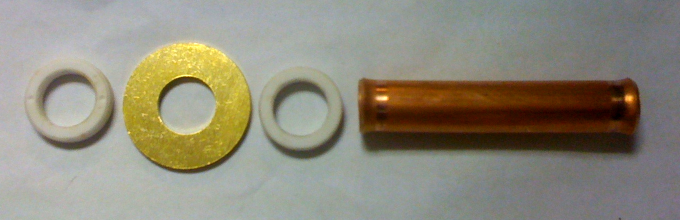
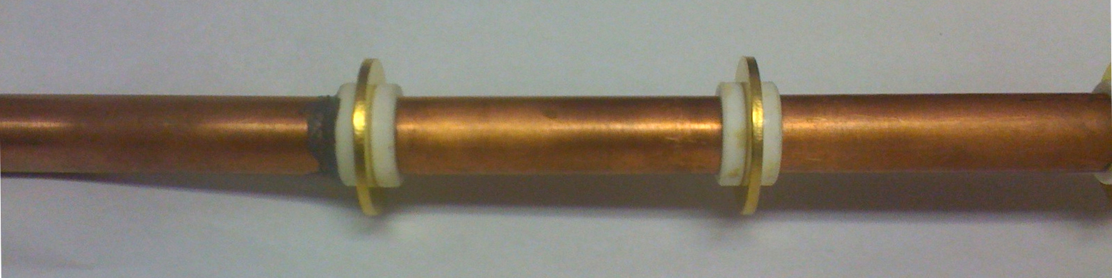
This is a “string of beads” design, with alternating anodes (brass washers) and cathodes (pieces of copper tubing). These are separated by ceramic bushings, as outlined on the first page in this set. Here are two relevant photos from that page:
(Sorry about the focus and lighting; these were taken with my previous telephone.)
This is a simple and straightforward design, and I hope that it will prove tractable in practice. I already have the parts, so construction should proceed apace. The power supply may be slightly more difficult, as it needs to balance all of the segments (I hope to use 5 or 6); but a few small chokes may help. With some luck, we’ll see.
(02 January, 2011, late evening)
I have started construction of this tube. Here are some relevant photos. First, attaching one of the anodes to one of the ceramic bushings:
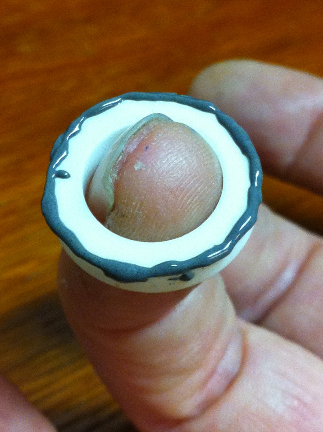
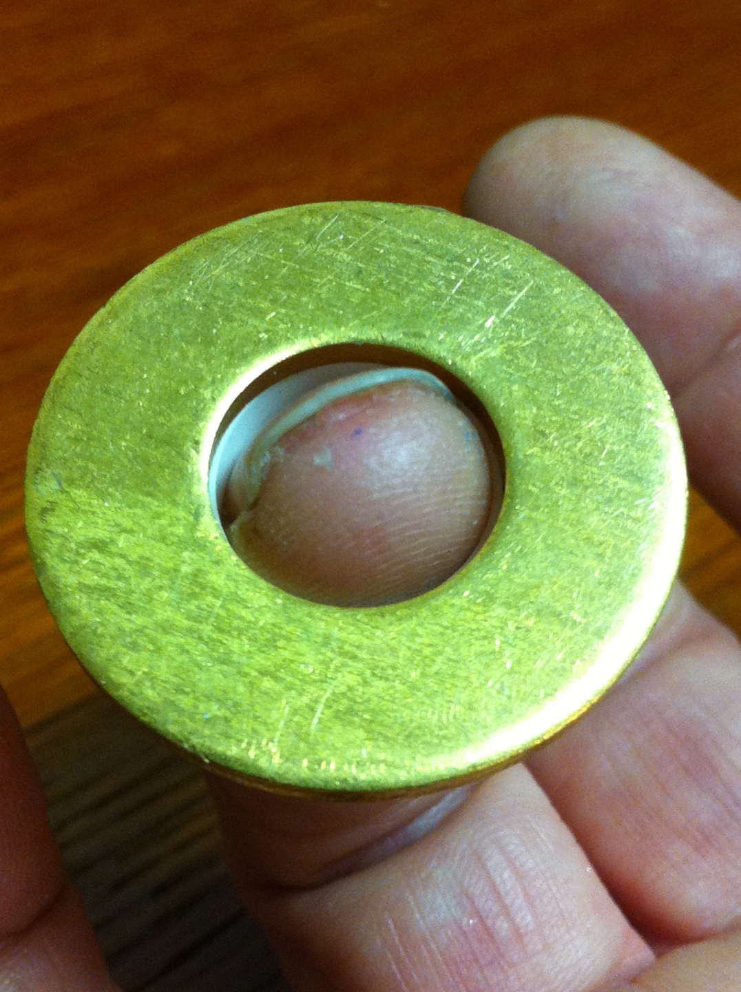
(After doing this the hard way a couple times, I discovered that my finger was a very handy holder for the bushing, and made application of the epoxy and attachment of the washer quite straightforward.) I have done six of these.
Next, attaching a ceramic bushing to one end of each copper tube:

It is a bit hard to tell in the photo, but I have done four of these. There is some chance that I may do a fifth one, but for the moment I am thinking that four will be enough; lasing at 780.8 nm has been observed in tubes as short as 5 cm. Four cathodes will require five anodes, which leaves the sixth one as a spare in case I change my mind. Once I build the tube, however, it will be difficult to change, as I will be using epoxy to hold the parts together.
(05 January, 2011, early AM)
I added the last anode this afternoon, and this sectional hollow cathode is now complete. Here it is, still on the mandrel:
(Note, the metal rod was too thin, so I wrapped paper around it, as you can see near the top of the photo, to expand it to the point at which it would hold the copper pieces reasonably firmly.) After I took this photo, btw, I removed the structure from the mandrel and stood it up to let the J-B Weld on the final anode cure.
I checked, and there is more than enough room for this on the existing base. In fact, I will probably have to knock one of the end fittings off and reposition it so I won’t need to use any glass tubing. (In case I need to change something, I prefer not to have to remove glass tubes that are epoxied in place.)
(05 January, 2011, evening)
Here are two side views of the tube, and one view down its axis. It is not possible to see this in the third photo, but there is a place where one of the cathodes has been compressed a little by the tubing cutter, and will obstruct a tiny bit of the beam. Otherwise it looks fairly reasonable to me.
In the meanwhile, I continue with my rebuild of the vacuum system. I am hoping to do a bit of testing later this evening.
(10 January, 2011)
I have decided to give the new vacuum manifold a page of its own, and I will continue to write about the lasers on this page instead of interrupting the flow any more than I already have.
(12 January, 2011, early AM)
The new manifold is complete and in place. It pumps down to about 20 milliTorr, which should be better than I need for this design, and I am proceeding with reconstruction of the laser. I have removed the quadrupole and the Brewster windows, and I have cleaned excess RTV from the end fittings. I made a pair of copper extension tubes so I won’t have to try to move either of the fittings, which is good because they are attached to the base rather firmly. [Note, added later: this turned out to be a significant issue.] I will probably take a look at putting all of this together tomorrow (actually later today, as it is already the 12th).
(late that evening)
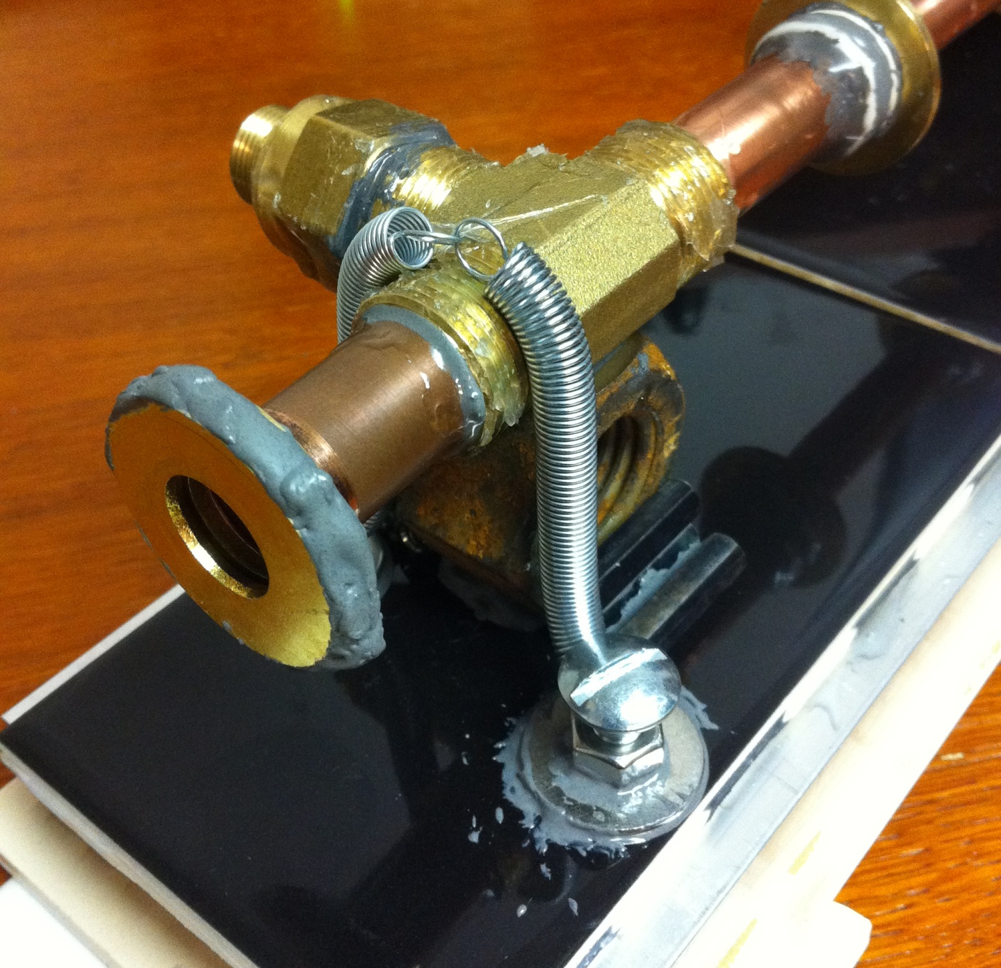
Here are some photos. First, an overview of the head:
Next, a view of the gas inlet end of the head, which should look slightly crooked...
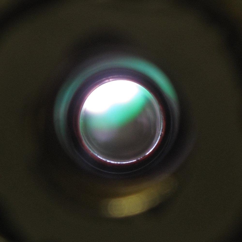
It appears crooked because it is crooked. I did not have (or at least did not think of) a good way to keep the end fittings correctly aligned when I was building the base, as a result of which they are both somewhat off-kilter. The crookedness is there to help compensate. (To keep things fairly straightforward, I have set up the new center section so that its axis, which is the optical axis of the laser, is reasonably well centered in the openings at the outboard ends of the fittings. These openings are where the mirror mounts will be attached, and it seemed reasonable to use them as references.) Here’s a view into one end:
There is, of course, no guarantee that this structure will lase, or even that it will sustain a reasonable discharge; but it is certainly worth a try.
(16 January, 2011, evening)
In consideration of the preceding sentence, I decided that it would be premature to install mirror mounts permanently on this head. It does, though, seem like a good idea to put extension tubes in place, so that if the head performs I will be able to emplace mirror mounts quickly. I have epoxied brass washers onto the ends of the extension tubes to facilitate this, and when that epoxy has cured I will install the tubes on the head.
It further occurred to me that because I do expect to put mirror mounts on the head eventually, I should not permanently attach the windows that I will be using for initial testing. I don’t want to hold them on with RTV, for reasons I’ve already mentioned. OTOH, it’s fine to let the air pressure from the outside hold them, and I can use o-rings to maintain the vacuum seal, as long as I figure out a way to prevent the o-rings from collapsing. (I should be able to find a washer or some sort of thin metal piece that can sit inside each o-ring and prevent it from deforming too badly, should that prove necessary.) Here is a photo of the extension tubes and the windows:
(17 January, 2011, afternoon)
I have glued the first extension tube into place, and I’m waiting for the epoxy to cure so I can flip the assembly upside down and glue the second tube. The plate on the end of this extension is not perpendicular to the optical axis, but it should be close enough to allow me to compensate without too much trouble. Photo forthcoming, when the network comes back up. (We are having a little outage at the moment.)
(18 January, 2011, early AM)
I have now epoxied the second extension tube into place. Again, photos forthcoming when our net access is reestablished. This page is invisible to the world until that happens in any case, so it can hardly make much difference.
(18 January, 2011, afternoon)
It is time to put this thing on the bench, and see whether it will hold vacuum. Debug is, I’m afraid, going to proceed slowly, though I may try using moderately fast-cure epoxy on any leaks I find, rather than J-B, which takes hours to harden significantly.
(a bit later)
Once I found some suitable o-rings (which did not show any signs of collapsing under stress, fortunately), the head went right down to a little over 50 Torr. That isn’t exactly what I had in mind, but it’s a start. I used the ultrasonic sniffer, found several leaks, and applied some fairly quick-setting epoxy; with any luck, I should be able to resume testing in an hour or two. I doubt that I have eliminated all of the leaks, but I hope I’ve made a good solid start on it.
(later, that same evening)
I was apparently wrong: the head pumped right down to 30 microns. I then set up the power supply and connected it to one anode (an outer one) and one cathode (the nearer inner one), and thus effectively brought up half of one side. I got a nice pink discharge at pressures of a few Torr, and it was possible to choose a voltage that resulted in bright pulses. (At the bottom of this range, the pulses were very irregular. As I increased the voltage slowly, they first became somewhat more frequent and a lot more regular; then they continued to become more frequent; and finally, when the voltage got high enough, the tube seemed to light continuously rather than blinking.) It is, for perceptual reasons, difficult to be entirely sure of the color, but at some points I thought I saw some deep blue near the walls, and at some points there really did appear to be a tiny bit of green in the discharge. The center, though, was mostly pink throughout, at least as far as I could tell by eye. I attempted to photograph the discharge, but I’m not sure I had much success; when I download the images I will post them here if they are worth looking at. (If not, I will probably try taking more and tweaking parameters, to see whether I can get better ones.)
There was a certain amount of sparkling and flashing, particularly at higher power input, some (or all?) of which may relate to contamination on the electrodes. I am hoping that this is not too bad, and that if there is any contamination it will clean up as I run the head.
In addition, I now need to figure out how to get both sides to fire together when I get them both connected. This may require triggering, in which case I will have to be careful to avoid damaging the power supply. It occurs to me that I could use the three middle anodes (let’s number them, so these are 2, 3, and 4) as actual anodes, and anodes 1 and 5 as trigger electrodes; alternatively, anodes 1, 3, and 5 could serve as anodes, and anodes 2 and 4 could be triggers. I have no idea whether either scheme would actually work, but it may be worth trying. (If I am supremely lucky, both sides may operate without any external triggering. That, however, seems quite unlikely.)
Here is a tentative photo of the discharge. As I mention above, this is only one cathode, though there is a disconnected cathode between it and the anode I was using.
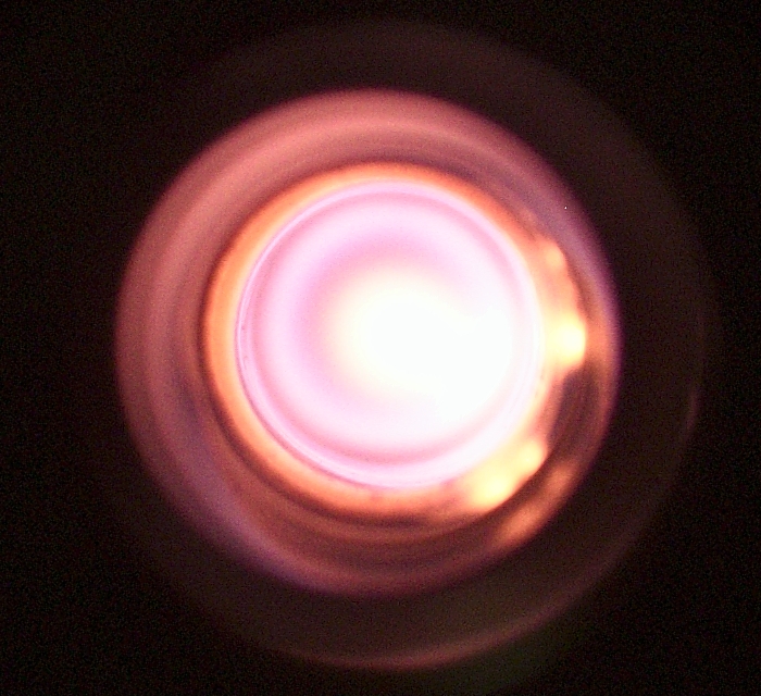
(700 px across is the largest I have right now; I will try to retake this.)
(20 January, late morning)
We are still off the Network, so this page is not yet visible (not that it matters at this time, and in any case it will be visible later on). I have taken more photos, but have not had a chance to process them yet; will post them as time and tide permit.
I do, however, have a happy report: I took one of our old EG&G TM-11 trigger units, ran one of the outputs through a 900-pf “doorknob” capacitor, and connected it to the center anode. With the output voltage turned all the way down, it still had no trouble triggering the discharge. This is a very good indication. It is important, of course, to avoid damaging the power supply with the trigger pulse; my thought is that the inductors on the two active cathodes are blocking most of the HV from the trigger unit, the capacitor across the power supply (an ancient Tobe Deutschmann jet-engine start cap that is probably rated for 2.5 or 3 kV) that is providing the energy for the discharge is snubbing most of the rest, and the rectifier, which is from a microwave oven and is probably rated for either 12 or 18 kV, is ignoring whatever remains. I ran quite a few pulses, and did not appear to have any problems.
When the voltage is just below the self-flash voltage of the head, a single trigger pulse will set off a little train of discharge pulses. This is okay; I can always dial back the power supply, which is running off a Variac™ or equivalent variable autotransformer. Also, if I want a train of pulses I can either build a little generator with a 555 timer chip, or just turn up the voltage until the tube begins to free-run.
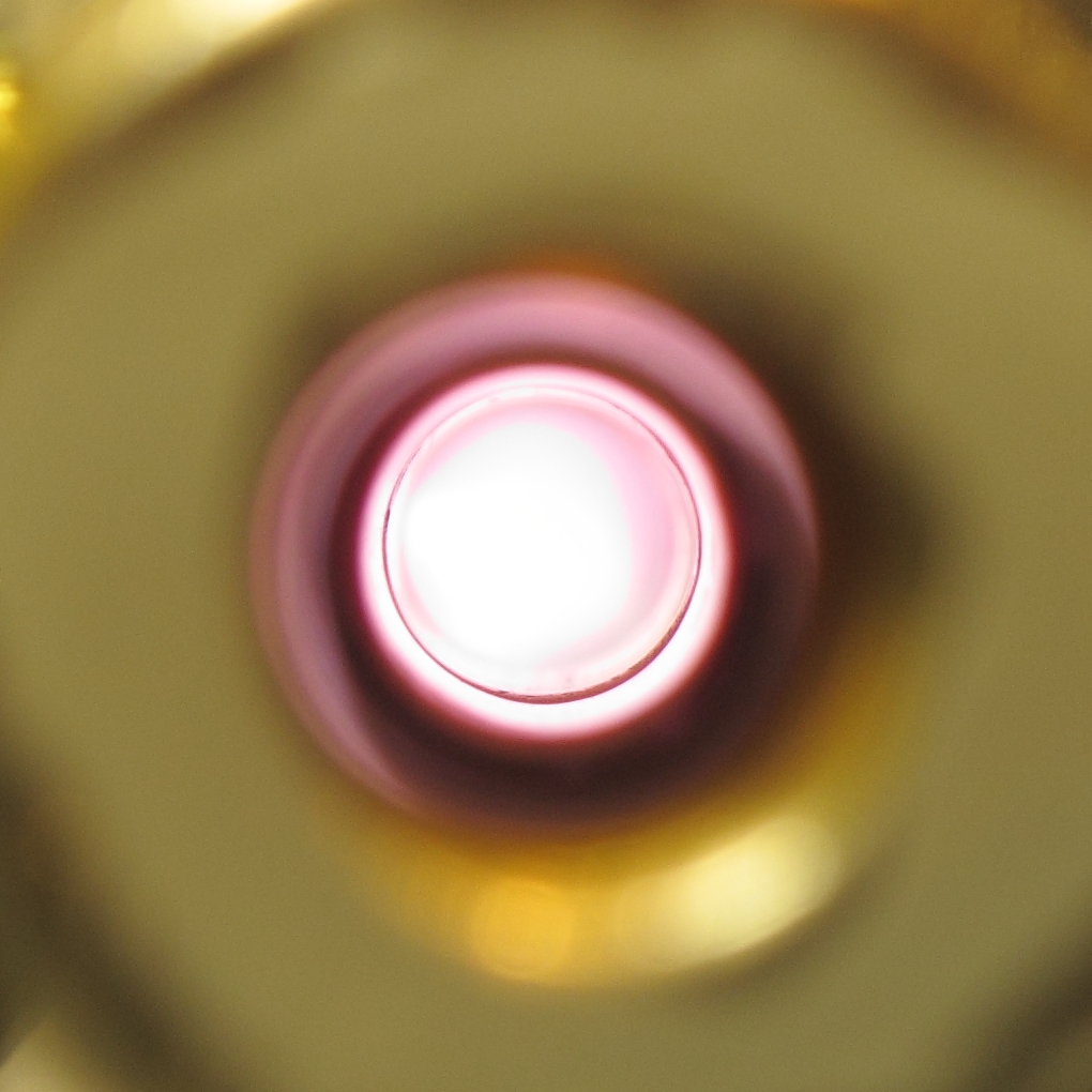
Here is a set of photos of “normal” discharges, with the camera focused at various places along the length of the head.
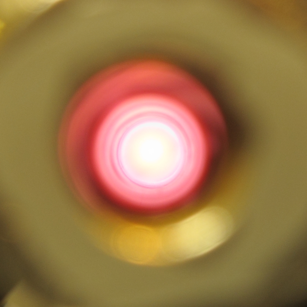

I think this color change represents pressure that is too low, but I’m not entirely certain:
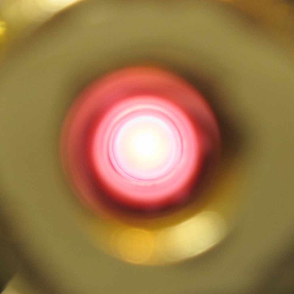
This appearance, however, is definitely associated with pressure that is too high. [NOTE, added much later: in actual fact, I have begun to think that all of these photos were taken at pressures that were too low: there wasn’t any significant amount of green light coming from these discharges. That changes, further down the page.]
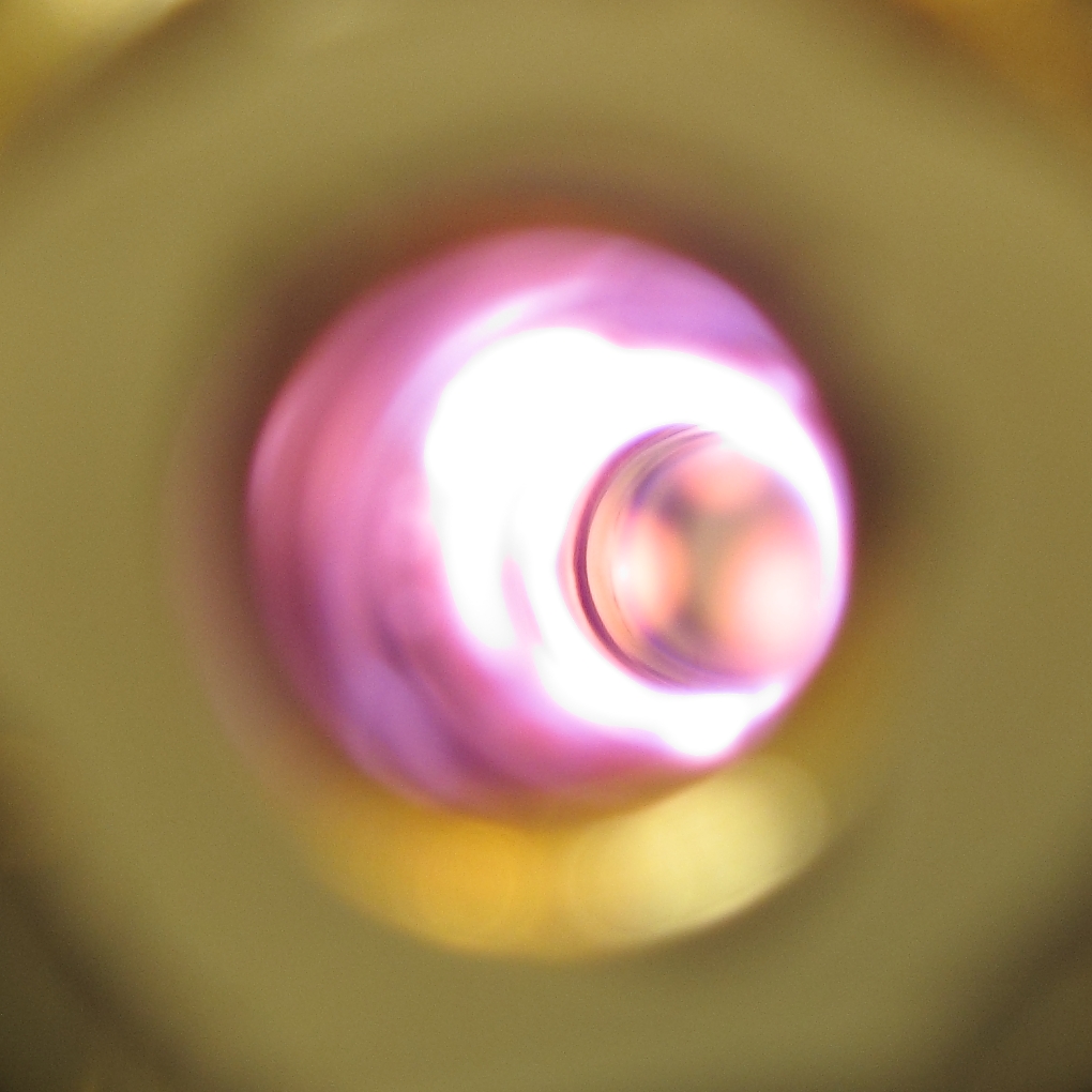
(I took this one at an angle, and you can observe several effects. The appearance is slightly misleading, though, so you will want to think carefully about what you’re seeing here.)
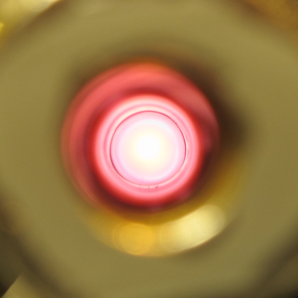
It appears to be possible, at some pressures, to get a donut-shaped discharge that hugs the wall. Here is a suggestive photo:
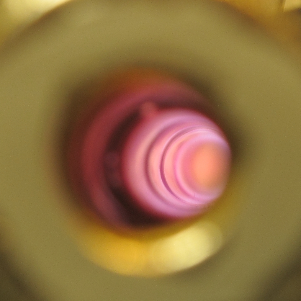
This may (or may not) prove to be useful. I need to
build mirror mounts and see whether I can get lasing at
all, though, before I try messing with special
conditions.
(2011.0214)
We had a network outage here, and this site was offline for a while. Things are apparently back to normal now and I have made some progress in the interim, though this head still isn’t a laser.
The mirror mounts are lousy, but I expected that. I may rebuild them; we’ll see. In the meanwhile, however, I did start testing, and quickly discovered that this design did not have the built-in springiness of the previous quadrupole design, so it was quite vulnerable to thermal expansion. After I ran it a bit too long one evening, it popped one of the end-fittings loose, and disassembled itself. I have rebuilt it; that end-fitting is now able to move along the base to accommodate thermal expansion, but is held so that it cannot move much from side to side, and is held down by springs so that it does not move up.
As you can see, I have added correction plates to the ends. They were misaligned badly enough that the mirror mounts probably wouldn’t have been able to deal. The alignment is still considerably less than perfect, but it is good enough for now. [Note, added later: I may add a second set of correction washers to the ends of the laser, so that the mirror mounts won’t need to have as much adjustment range.]
I have also changed the topology slightly: I am now using anodes 2 and 4 along with cathodes 2 and 3. I have not yet changed the triggering, but I intend to: I want to put the + output of the trigger unit on anodes 1 and 5, and the - output on anode 3. That should get me better triggering. I have been free-running the head, which is fine, but I also want to be able to trigger it.
I have discovered that I need to push the discharge a lot harder than I did for the photos above. Copper gives a significant green color to a discharge, and as you can see, there is no particular hint of green in those images. Unfortunately, in order to get some green I have to hit the tube hard enough to cause what looks like some instability near the anodes (white area above the green glow) —
I am hoping that this will not prevent lasing, but it is too soon to tell.
One other thing I think I will do very soon is put 4 or 8 nf across each cathode and its corresponding anode. If I am exceedingly lucky, that could produce lasing on the yellow and green lines of atomic copper. No guarantee, of course, but I think it’s worth a try. It may also have some effect on the stability of the discharge, but that remains to be seen.
(2011.0228, evening)
I am applying another washer to each end of this structure, as mentioned above. This is a slightly complicated process. First, I smoothed and polished the washers, to help keep vacuum leakage to a minimum. Then I temporarily attached a flat mirror to one of them with 3 dabs of RTV. Then I aligned a HeNe laser to the tube, and positioned the washer and its attached mirror so that the return beam is close to center on the HeNe. It is not fully centered, but at least it is close. I have applied dabs of RTV to stabilize the washer in position. When the RTV has cured I will probably tweak the alignment a bit to see if I can improve it before I apply dabs of J-B Weld epoxy to set the washer firmly in place.
Once the washer is held solidly in place with epoxy, I can remove the dabs of RTV and apply epoxy all around its rim as a vacuum seal. Then, of course, I have to do something similar at the other end; but that end is too close to the alignment laser, so it will be trickier to achieve good alignment. My hope is that I will be able to align the two mirrors to each other, as well as to the HeNe. (This produces an interference pattern that will, I hope, be visible on the target at the front of the HeNe.) If that works (or even if it doesn’t), I will set the second washer firmly in place, remove both mirrors, make sure I can pull vacuum on the head, and resume testing.
In the meanwhile, I will be setting up an interrupter to run the laser for part of each second. My hope is that this will help prevent the head from overheating. I may also attempt to get the laser to respond to pulses from the trigger unit, which has been difficult up to now.
(2011.0308, early AM)
I have the vacuum system rebuilt now, and (mirabile dictu) it seems to hold vacuum almost as well as a real system would. True, it still leaks; but I left it for almost half an hour, and the pressure only went up from about 5 microns to perhaps 12. That’s far better than I need for this project, and also far better than I’ve ever done before.
Once I get the power supply reconstructed and the once-a-second interrupter rebuilt, I will resume testing on this laser head.
[[More as it transpires...]]
(02 January, 2011, afternoon, ff)
Here are some useful abstracts. In some cases I have
found and read the article at the University library or
online; in others I am probably going by what I have
found in the abstract, as that was enough information to
get me started.
Longitudinal hollow cathode copper ion laser:
optimization of excitation and geometry (Proceedings
Paper)
Diana B. Mihailova; Margarita G. Grozeva; Annemie
Bogaerts; R. H. Gijbels; Nikola V. Sabotinov
Proceedings Vol. 5226, 12th International School on
Quantum Electronics: Laser Physics and Applications,
Peter A. Atanasov; Alexander A. Serafetinides; Ivan
N. Kolev, Editors. (4 November 2003) pp 49-53
Abstract
It is demonstrated experimentally that for copper ion lines laser excitation in a longitudinal hollow cathode discharge (HCD) an optimum current density (approximately 1 A/cm2) exists. Above this value a saturation and even decrease of the laser power is observed. Due to the axial inhomogeneity of the longitudinal discharge the possibility to increase the laser power by increasing the cathode length is also limited. To determine the proper cathode length for a sputtering copper ion laser, the axial current and spectral lines intensity distribution at conditions typical for laser oscillation are measured, showing a maximum at the anode ends of the cathode. Numerical modeling for exactly the same discharge conditions and tube design is also performed. The results are compared with the measured data and reasonable agreement is reached. Based on the results of the experiments and calculations we have demonstrated that the most efficient laser oscillation is achieved when the laser active volume comprises a series of anodes and cathodes, each cathode with a length of approximately 1 x 2 cm.
[Note: the “x” between 1 and 2 in that last sentence is actually a “divided by” sign. When I find the correct HTML code, I will restore it. Unfortunately, I am not entirely sure what they meant by it.]
The conclusions here put a severe limit on the
performance I can expect to get from my “string of
beads” sectional tube, with alternating anodes and
cathodes; but at least it appears that such a tube can
be a viable laser. The next reference explains the
rationale for the designs I discuss on the previous
page.
Comparison of Cu-II 781 nm Lasers Using High-Voltage
Hollow-Cathode and Hollow-Anode-Cathode Discharges
K. A. Peard, Z. Donko, K. Rozsa, L. Szalai, and R. C. Tobin
IEEE Journal of Quantum Electronics, V30N9 (Sep 1994) pp 2157-2165
Abstract
Voltage-current characteristics and the Cu-II 780.8 nm laser performances are described for a novel segmented hollow cathode and for three- and four-slot hollow-anode-cathode (HAC) tubes. Each of these operate[s] at a higher voltage and with higher slope resistance than a conventional hollow cathode, and [they] produce improved laser performance. The best laser performance is obtained with the segmented tube. The application of a longitudinal magnetic field raises the discharge voltage and enhances the laser performance for the segmented tube, and raises the voltage for the four-slot HAC tube. The magnetic field lowers the voltage and reduces the laser performance with the three-slot HAC tube. The voltage effects are attributed to the deflection of the fast electrons by the magnetic field strength, and represent experimental evidence for the oscillation of electrons in a hollow-cathode discharge.
Note: I have performed minor editing on this, adding a
few commas and the items enclosed in square brackets.
This is a crucially important paper; it is probably
available on the Web in PDF format.
On to the next page, (more information about quadrupole designs)
Back to the parent page of this set
To the Joss Research Institute Website
To my current research homepage
My email address is a@b.com, where a is my first name (just jon, only 3 letters, no “h”), and b is joss.
My phone number is +1 240 604 4495.
Last modified: Wed May 10 15:11:26 EDT 2017