(22 October, 2010, ff)
This pageset deals with two sorts of hollow-cathode lasers: metal vapor (excluding iodine for the moment), and argon or iodine. The designs are nearly identical, except that the metal vapor lasers must provide metal for the discharge, and in a hollow-cathode laser of this sort the metal is sputtered from the electrodes; argon and iodine are introduced with the buffer gas, which is helium. (Iodine has been classed as a metal vapor laser, and in fact I believe it was the first laser of the helium-metal type to be described in the literature.)
My hope is to generate designs that DIYers can reasonably hope to build and operate. The first one will probably operate with a mixture of helium and argon. If I can get that to work well, I will probably try it with helium and iodine. After that, I hope to move to helium and zinc, perhaps with a small amount of argon to help sputter the zinc into the discharge, and finally helium and copper, also possibly with a small amount of argon.
[Note, added later: The He-Ar laser operates at rather low pressures, a few dozen microns, and my initial attempts at constructing a suitable head were informative but unsuccessful. In the long run, it is more likely that my first working hc laser will be either He-I2 or sputtered copper vapor.]
(22 October, 2010, ff)
Quite a few metal vapor lasers are known; they operate at many wavelengths, from some microns in the IR to fairly shortwave UV. Some of them utilize neutral atoms, some use ions. Among these, the best-known to DIY laser builders is the neutral copper atom laser, which emits self-terminated pulses about 35 nsec long at 510.6 nm (green) and 578.2 nm (yellow). It is probably the most efficient metal-vapor laser, but it requires fairly fast pulsing and probably fairly high voltages, and may not be quite as well suited to this sort of design as the other typical copper-vapor laser...
Singly-ionized copper emits at 780.8 nm, a far-red line that is visible to many people, but does not appear very bright. Also, because the copper atoms must be ionized before they can be excited to the upper laser level, this laser is significantly less efficient than the yellow/green laser. The advantage of the red line is that it can operate CW and in very long pulses, and it has high gain, which should make it relatively easy to achieve, ...or so we hope, because I am probably going to try.
Supplying copper atoms to the discharge is not exactly trivial. The first copper-vapor lasers used copper metal, which was added to the buffer gas by heating it up until it reached a temperature at which it has adequate vapor pressure. This involves temperatures of well over 1000° Celsius, and is painful. The Cu(I) halides have much lower melting and boiling points, and they soon proved to be suitable, though at low repetition rates they require double-pulsing. (The first pulse dissociates the halide, releasing copper atoms into the buffer gas; the second pulse, a few μsec later, lases the resulting copper atoms.) A copper halide laser typically operates at 400-470° C. These lasers can be heated externally, but if the pulse repetition rate is high enough the discharge heats itself, and it is sufficient to surround the laser tube with appropriate insulation. The tube itself also has to be chosen carefully, so that it will handle the heat. Fortunately, fused silica works well at temperatures of a few hundred C. Unfortunately, it is generally rather expensive, and it is quite brittle.
Copper acetate operates at much lower temperatures; but I would guess that it rapidly decomposes, and is suboptimal for that reason.
[[Reference:
Laser action in copper with copper acetate as a lasant
G. Chakrapani, T. A. Prasada Rao, A. A. N. Murty, and D. Ramachandra Rao
Appl. Phys. Lett. V31 (1977), p 832
It appears, from the article, that copper acetate works reasonably well at 230° C. It is not hard to reach this temperature, but I am not yet aware of any DIY copper-vapor laser that has used copper acetate.]]
There are many other metal vapor and helium-metal lasers. Zinc ions lase with reasonable gain, and they emit in a region of the spectrum that is easy to see, not far from the two most common wavelengths of the argon laser, around 492 nm. Zinc has the advantage of melting at a much lower temperature than copper, and it has usable vapor pressure at temperatures that are far more easily reached by the DIYer. Because this laser requires ions it is not as efficient as the neutral atomic copper laser, but it is still attractive for DIY construction.
Lead vapor lases at 722.9 nm, and a few DIYers have built lead vapor lasers, but there is the inevitable toxicity issue, so a certain amount of care is required. The same is true of the helium-cadmium laser and helium-selenium lasers, and the helium-mercury laser.
Gold vapor lases at 627.8 nm, but I am not aware of any DIY gold lasers, for two reasons: first, helium appears not to work very well as a buffer gas for this laser. (Various papers describe the use of a mixture of neon and hydrogen.) Second, presumably because gold is expensive; and third because it probably has to be used in metallic form, which means that high temperatures are required unless the metal is sputtered into the discharge.
As mentioned above, iodine is another laser in this class. Iodine ions have a number of laser lines, primarily from the orange on into the IR, but also at a few green and blue wavelengths. The strongest wavelengths appear to be 576.1 nm, 540.7 nm, and 612.7 nm; there is at least some chance that the last of these might work with HeNe optics, which is convenient for the DIYer. Suitable vapor pressures for the He-I2 laser are reached at summertime room temperatures, which also makes it convenient. [I will return to this system.]
Most or all of these lasers have been operated in positive-column discharges [think of a neon sign or a HeNe tube], but there is a problem with that approach. As some readers may have observed with HeNe tubes, if you try to increase the current beyond the optimum level, which is typically a dozen mA or so, the output saturates and starts to decrease. Although positive column designs are easy to build, for this reason they are not particularly good here. There is another interesting approach, however, which involves using a hollow-cathode discharge.
Hollow-cathode lasers tend to have increasing output up to the point at which the discharge becomes unstable and they start to arc over. This often occurs at far higher current densities than are useful in positive column discharges (though at lower voltages), and hollow-cathode lasers tend to have substantially higher output power. Also, it is often possible to sputter the required amount of metal into the buffer gas at room temperature or at temperatures that are only slightly elevated, which makes hollow-cathode designs particularly attractive for DIY construction.
Early hollow-cathode designs typically used a bar of the
appropriate metal, into which a slot was milled. Above
this slot were positioned individually-ballasted pins,
often made of tungsten [wolfram]. Such a design is
fairly easy to build if you have a milling machine and a
bar of very pure metal (or, in the case of the
helium-iodine laser, stainless steel), but not if you
don’t. There have, though, been many other HC
laser designs. My hope here is to provide a design that
provides good performance and is constructed as much as
possible from parts that can be obtained at hardware
stores and hobby shops, using materials that are not
difficult to locate or fabricate.
(16 February, 2010, ff)
I have not yet seen any DIY hollow-cathode metal-vapor lasers, and it seems to me that it is past time for one.
As far as I am aware, no DIYer has ever built a 780.8nm copper vapor laser either, so one of the objectives of this project is to see whether the structure I have in mind will work at that wavelength. Getting it to work at all, however, comes first.
(It turns out that at least one group has used copper bromide in a hollow-cathode tube, btw; but I believe they ran the tube at the usual elevated temperatures, so it is not of particular interest here.)
The first step in a project of this sort is to glean some information from published work. [[When I wrote that I had read several abstracts, but I had not yet managed to get to the University library to read the actual papers. We had just gone through two large snowstorms in a row, and the University was actually closed for a brief period. I have since scanned a few relevant publications.]]
I have had several notions about buildable designs. I will gloss one or two of the early ones here, as I still hope to build at least one such tube eventually. My first idea for a single-section testbed device was about as follows:
                 anode                anode
                  ||                   ||
                  ||iii             iii||
==================||iii\           /iii||==================
                  ||    -----------    ||
(Pyrex end tube)          cathode
                  ||    -----------    ||
==================||iii/           \iii||==================
                  ||iii             iii||
                  ||                   ||
(Please forgive the ASCII-picture; I will substitute something better when I have a chance.)
The cathode, in this case, is a piece of copper tubing with flared ends, and the anodes are stainless steel washers. "iii" is an insulator. (As it happens, I have acquired two “Roman glass” bead rings for this purpose; this will probably be the only laser in the world with truly antique glass insulators — the shop owner said that these rings could be as much as 1000 years old.) Because I will probably be dissipating a fair amount of power in this device, I will seal it with high-temperature automotive gasket forming silicone rubber. That should permit it to get quite toasty without damage if I fail to cool it adequately. (Permatex® “Ultra Copper®” RTV is rated for 371° C intermittent service. That’s almost enough to let the laser operate in the usual furnace mode!)
[Note, added 24 February, 2010: I have now read several articles, some of which are listed in the References, and there are some photos below.]
The power supply is operated at negative polarity, so that the ends of the active section (the anodes) are at ground potential. This means there won’t be any voltage gradient along the Pyrex™ tubes that lead to the gas inlet and outlet. This helps prevent (or at least slow down) the accumulation of “junk” on the end windows. (Also, it is counterproductive to allow the power supply discharge to the vacuum pump instead of the laser!)
I think I now have nearly everything I need to build this test structure, and I will start constructing and photographing as time permits.
(18 February, 2010, early am)
Here are the anodes, the insulating spacers, and the cathode:
Here is the beginning of assembly:
(As you can see from the copper pipe that I am using to hold the cathode section in a more or less vertical orientation, I have also begun to acquire parts for a larger version with perhaps a dozen sections. That, however, will wait, as I do not yet know how long an individual cathode section can be and still sustain a discharge through its entire length. My guess is that I will be able to use segments with length of several times their internal diameter, but for now that’s just a guess.)
I intend to use helium as the buffer gas for this laser. Neon is reported to be better, but it is also at least 5 times as expensive, and I do not already have it on hand. I may add a small amount of argon, which (according to one of the papers I’ve read) enhances the sputtering a bit.
(18 February, 2010, afternoon)
Although I have found out variously that it doesn’t pay to rush, I’m still impatient. I have put the first spacer on the tube section, and now I need to wait for the RTV to cure before I add a second one. Once all three spacers are in place I can add the outer Pyrex tubes. I am afraid that final assembly will be somewhat tweaky and difficult because the gasket-maker material does not adhere well to glass; we’ll have to see how things go when I tighten the compression fittings.
As of now, I expect to use a large ceramic tile as the baseplate for this tube. If I orient it along a diagonal, I should have room for mirror mounts.
(24 February, 2010, afternoon)
Here is the assembled section. I used a piece of stainless-steel tubing as a mandrel when I added the two pieces of Pyrex tube at the ends, and I left it in when I took the photos; it has since been removed.
I now need to set up a plinth, mount this thing,
cobble together a power supply (and work out a
way to make connections), and test it.
[[Slight delay for other projects, and for a partial rethink...]]
(16 April, 2010)
I have rebuilt the tube, and will post photos when I
get a chance. I still need to reinforce it, so I can
make the electrical attachments and mount it without
tearing it apart. I expect to use a water-aspirator
as a vacuum pump, which will aid in portability if I
want or need to demonstrate this laser, and I am
currently thinking about using a power transformer
from an old microwave oven to run it, as it will
probably want only about 800 V or perhaps even less.
(06 August, 2010)
The small tube was difficult to construct and stabilize, so I have retrenched, and I am building a larger tube. I have also decided that because J-B Weld epoxy can handle 500° F., I should be able to use it to hold the parts together. This will create a much stiffer and more stable structure. (Eventually I will probably also use it to rebuild the small laser, as it would be nice to have a unit that is easily portable. In the meanwhile, however, what I have in mind is a version with a bore of roughly 12 mm.)
[Note, added 08 August: that didn’t last long. See below for the {inevitable} change of plans.]
Here is a temporary photo of part of a preassembly, taken with my telephone (which is why it is not particularly well focused):
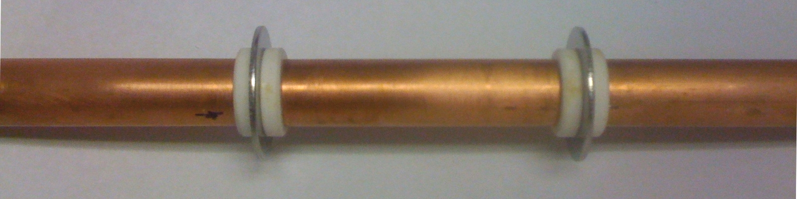
I am using ceramic bushings as insulators, with steel washers possibly serving as anodes. The sections of copper tubing are about 2½" long except for the ones at the ends, which are about 3" long.
It remains to be seen how well this will work. My hope, of course, is that I will get enough gain for some sort of lasing, probably on the far-red line first, as that is easier at low voltages.
NOTE: This (photo, above) is a very preliminary look; I still have to make electrical attachments to the parts. I also have to set up end fittings with gas and vacuum connections, and either windows or mirrors. Fortunately, the melting point of ordinary solder is lower than 500° F., so I may be able to do initial assembly before I work up the electrical connections, at least those that go to the copper. (I am likely to drill a hole in each of the washers, and use small bolts for those electrical connections.)
My record of this project continues on
the next page,
but the specifics of the “string of beads”
tube designs are on
the page after that.
In addition to reading some general material about
copper-vapor lasers and about hollow-cathode discharges
and discharge devices, I also read a number of research
papers, in particular the following:
---------------------------------------------------------
Practical small-scale hollow-cathode cw metal-ion lasers
---------------------------------------------------------
The spatial distribution of small signal gain in a
segmented hollow cathode discharge laser
---------------------------------------------------------
High-Gain Ultraviolet Cu-II Laser in a Segmented Hollow
Cathode Discharge
---------------------------------------------------------
To the Joss Research Institute Website
To my current research homepage
My email address is a@b.com, where a is my first name
(just jon, only 3 letters, no “h”), and b is joss.
My phone number is +1 240 604 4495.
Last modified: Wed May 10 15:09:25 EDT 2017
References
H. Tsuda and J. A. Piper
J. Phys. E: Sci. Instrum., V22(1989), pp 462-465
T. M. Adamowicz, Z. Donkó, L. Szalai, K. Rósza, W. Kwaśniewski
Applied Physics B: Lasers and Optics, V65(1997), pp 613-618
Zoltán Donkó, László Szalai, Károly Rósza, Maria Ulbel, and Manfred Pöckl
IEEE J. Quantum Electronics, V34N1 (January, 1998), pp 47-53
This work was supported by
the Joss Research Institute
Contact Information: